F
ACULDADE DEE
NGENHARIA DAU
NIVERSIDADE DOP
ORTODevelopment of an ARGOS beacon for
the VORSat CubeSat
Nuno Filipe Sousa Cardoso
Master in Electrical and Computers Engineering Major in Telecommunications
Supervisor: Sérgio Reis Cunha (PhD)
c
Resumo
Cada vez mais os satélites tem uma maior importância na recolha de dados, na transmissão de informação e nas comunicações a nível mundial. É cada vez mais frequente o envio de satélites para a atmosfera de modo a que estes possam recolher dados para experiências ou mesmo para o ser humano entender melhor o meio ambiente que o rodeia.
Esta dissertação nasce de um problema criado pela reentrada dos satélites na atmosfera e na necessidade de desenvolver um sistema fiável que possibilite a localização do satélite mesmo depois da reentrada.
O satélite a ser lançado para a atmosfera é um CubeSat. Um CubeSat é um satélite de pequenas dimensões, normalmente de 10*10*10 cm, que tem como vantagem ser um satélite de baixo custo e de fácil produção. Estes satélites são extremamente versateis e são usados por universitários, pelo mundo fora, para explorar o espaço. Devido a sua constituição este satélite é extremamente complicado de recuperar após a sua reentrada.
Com esta necessidade como fundo, esta dissertação tem como objectivo o desenvolvimento de um beacon ARGOS que será incorporado no VORSat (VHF Omni Directional Radio Range Satellite). O VORSat consiste num programa que visa o desenvolvimento de um pequeno satélite. Este programa esta a ser desenvolvidos por alunos na Faculdade de Engenharia da Universidade do Porto (FEUP). Este projecto diz pretende enviar um satélite para a LEO (Low Earth Orbit) e recuperar a ERC (Earth Reentry Capsule) após a sua reentrada na atmosfera terrestre. Pretende-se que este beacon tenha um baixo consumo de modo a maximizar a vida útil das baterias que irão a bordo do satélite.
Numa primeira fase foi feito um estudo a cerca dos beacons já existentes, bem como, um estudo sobre o sistema ARGOS/GPS que será o sistema de comunicação utilizado.
Numa segunda fase será construída uma PCB (Printed Circuit Board) de teste que conterá um oscilador local a frequência de 401.65MHz, um modelador I/Q, um amplificador de potencia RF, uma antena e um microcontrolador. Todo o dimensionamento deste sistema tem em conta os consumos e optimização dos mesmos tentado reduzi-los ao máximo. Esta placa servirá para testar a solução adoptada.
Numa segunda fase será projectada uma versão, da primeira PCB, miniaturizada de modo a que esta possa ser integrada no satélite.
Desta forma o produto final desta dissertação será um beacon que irá emitir a localização do nosso satélite após a reentrada do mesmo na atmosfera terrestre de modo a que este possa ser localizado e posteriormente recolhido.
Abstract
Nowadays, satellites have a very relevant role in data collection, transmission of information and worldwide communications. It is becoming more and more common to send satellites into the atmosphere so that they can collect data for experiments or even to better understand the environment that surrounds the Earth.
This dissertation is born to solve a problem created by the reentry of satellites in the atmo-sphere and the need to develop a credible system that allows the location of the satellite even after its reentry.
The satellite that will be launched into the atmosphere is a CubeSat. A CubeSat is a small satellite, with the typical dimensions of 10*10*10 cm, which has the advantage of being a low cost and easy production satellite. These satellites are extremely versatile and are used by univer-sity students around the world, to space exploration. Because of its constitution, this satellite is extremely difficult to recover after its reentry.
With this need as background, this dissertation aims to develop an ARGOS beacon that will be incorporated into the VORSat. The VORSat is a small satellite program that was being developed by students at Faculty of Engineering of the University of Porto. This project regards send a satellite to the LEO and to recover the Earth Reentry Capsule (ERC) after its reentry. It is intended that this beacon has a low consumption to maximize the battery life time.
In a first phase a study was made about the existing beacons, as well as a study about the ARGOS/GPS system that is used in communication.
In a second phase, a PCB was built. This PCB contains a local oscillator with the frequency of 401.65MHz, a I/Q modulator, a RF power amplifier and a microcontroller. The whole design of this system takes its optimization and the reduction of its power consumptions into account. This board serves to test the adopted solution.
In a third phase, the projected version of the first PCB was miniaturized so that it can be integrated into the satellite.
Thus, the final result of this dissertation is a beacon that will broadcast the location of our satellite after its reentry into Earth’s atmosphere, so that it can be located and subsequently re-trieved.
Acknowledgments
I begin by extending my thanks to Prof. Dr. Sérgio Reis Cunha for how much he contributed to this document and the whole project, whether by the documentation provided, the ideas of how to implement the system or suggestions on how to achieve the objectives that I proposed to accomplish.
Likewise, I want to thank Faculdade de Engenharia da Universidade do Porto to have been, during these past seven years, my second home. It was the only place where I could focus at work and was also where I met my best friends. And it is to them that I say thank you, for all the moments from the laughs to the discussions or since the more laborious nights to the most relaxing parties. I also wanted to thank those who most closely accompanied and supported me in these hard times. All of you have given life and meaning to an experience that could have been, in another way, too boring and uninteresting.
I also want to extend my thanks to Nuno Sousa and Rui Fernandes for the willingness shown to provide me access to the laboratories and in everything I needed. I also want to thank João Soares Silva for the productive discussions we had.
Before concluding, it is necessary to equally thank Ricardo Rodrigues for all of his patience and friendship during these seven years. I have always been able to count on him, especially when the nerves took control of me.
Finally, I thank my parents for believing, from the very beginning, that I would be able to com-plete my degree and for all the sacrifices they made for me to reach this goal. Thanks especially for the patience and affection that they had with me in the hardest moments.
Nuno Filipe Sousa Cardoso
“À minha avó paterna Aurora Abreu. Aos ausentes sempre presentes.”
Nuno Cardoso
Contents
1 Introduction 1
1.1 Context/Scope . . . 2
1.1.1 The VORSat Project . . . 2
1.2 Motivations and Objectives . . . 4
1.3 Document Structure . . . 5
2 State of the Art 7 2.1 Argos . . . 7
2.1.1 Introduction . . . 7
2.1.2 History . . . 8
2.1.3 Developments in the System . . . 8
2.2 Argos - 2 . . . 10
2.2.1 Characteristics . . . 10
2.2.2 Transmitters and PMTs . . . 11
2.2.3 Devices . . . 11
2.2.4 Operating Modes of Communications . . . 12
2.3 Location Technologies . . . 13
2.3.1 Argos . . . 13
2.3.2 GPS - (Global Positioning System) . . . 15
2.3.3 Argos/GPS . . . 17
2.3.4 GPS phone tag . . . 19
2.4 Summary . . . 21
3 Dimensioning of the Beacon 23 3.1 Adopted Topology . . . 23
3.2 Choice of the Components . . . 24
3.3 Choice and sizing of the remaining components . . . 27
3.3.1 Switches . . . 27
3.3.2 Oscilator Control . . . 29
3.3.3 Dimensioning of the opamp as an inverter . . . 31
3.3.4 I/Q modulator . . . 32
3.3.5 Control system for the DC / DC converter . . . 32
3.3.6 Calculation of the transmission line . . . 33
3.3.7 Control of the microcontroller . . . 34
3.3.8 Dimensioning of the system for energy storage . . . 35
3.4 Summary . . . 35 xi
xii CONTENTS
4 Implementation 37
4.1 Hardware Implementation . . . 37
4.2 Software Implementation . . . 38
4.2.1 Filter Design . . . 42
4.2.2 Treatment of the data coming from the GPS . . . 45
4.3 Summary . . . 47
5 Tests and results 49 5.1 Tests performed . . . 49
5.1.1 Hardware Tests . . . 49
5.1.2 Firmware Tests . . . 55
5.2 Miniature Version of the PCB . . . 63
5.3 Summary . . . 63
6 Conclusions and Future Work 65 6.1 Summary of the performed work . . . 65
6.2 Concluded Objectives . . . 66
6.3 Future work . . . 66
A Expressions, Calculations and Results 67 A.1 Sizing of the opamp as an inverter . . . 67
A.2 Calculation of the transmission line . . . 67
A.3 Calculation of the values for sinusoidal wave . . . 68
B Design of a PCB 71 B.1 Problems . . . 71
B.2 Noise reduction . . . 71
B.3 Distribution of Components in the PCB . . . 72
B.4 Impedance Control Techniques . . . 72
C Encoding the Base band signals 73 C.1 Manchester encoding . . . 73 D PCB Footprints 75 D.1 PCB Test Version . . . 75 D.1.1 Bottom View . . . 75 D.1.2 Top View . . . 76 D.2 PCB - Miniaturized Version . . . 76 D.2.1 Bottom View . . . 76 D.2.2 Top View . . . 77
E Power Consumption Graphics 79
List of Figures
1.1 An example of an ERC. The radius of the capsule is approximately 5cm. [1] . . 3
1.2 Comparative analysis between two different landing sites [2] . . . 3
2.1 Evolution of the data transmission system [3] . . . 9
2.2 Probability of reception by Argos-1 and 2 satellites vs. platform density [4] . . . 11
2.3 Reception area of a signal for a satellite [5] . . . 13
2.4 Principle of location by the Doppler effect [5] . . . 14
2.5 The positioning based on Least squares analysis [5] . . . 15
2.6 The GGA message [6] . . . 16
2.7 The RMC message [6] . . . 17
2.8 The Argos/GPS system architecture [5] . . . 17
2.9 Errors in calculations of approximations [5] . . . 19
2.10 Example of a GPS phone tag device [7] . . . 20
3.1 Simplified architecture of the proposed solution . . . 24
3.2 Characteristics of the modulators . . . 26
3.3 Power amplifier - typical configuration[8] . . . 27
3.4 Id vs Vds [9] . . . 28
3.5 MosFet as a Switch . . . 29
3.6 Functional block diagram [10] . . . 30
3.7 Tipical PLL configuration [10] . . . 30
3.8 VCP power Supply . . . 31
3.9 Opamp - inverting configuration . . . 32
3.10 I/Q modulator - basic configuration . . . 33
3.11 Supply circuit for the DC/DC converter . . . 33
3.12 Architecture of the proposed solution . . . 36
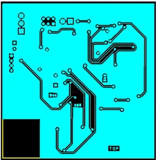
4.1 Top PCB footprint . . . 38
4.2 Botton PCB footprint . . . 38
4.3 Prototyped Beacon - bottom view . . . 39
4.4 Flowchart from the program main . . . 40
4.5 Flowchart from the USART interrupt . . . 41
4.6 Flowchart from the Timer interrupt . . . 42
4.7 Example of a spectrum signal with side skirts . . . 43
4.8 Matlab code for the FIR filter generation . . . 43
4.9 Impulse response of the filter . . . 44
4.10 Example of the effect of the filter in the DAC output waveform . . . 44
4.11 Example of the filtered signal . . . 45
4.12 Manchester encoding . . . 47 xiii
xiv LIST OF FIGURES
5.1 PLL muxout waveform . . . 50
5.2 VCO output . . . 50
5.3 DAC output waveform . . . 51
5.4 Opamp output to an 8 sample sine wave input . . . 52
5.5 I/Q modulator output wave, with a 1KHz sin wave as an input . . . 52
5.6 Sin wave with 1KHz of frequency recorded with matlab . . . 53
5.7 RF power amplifier output, with modulated a 1KHz sin wave as an input . . . . 54
5.8 Battery lifetime with a Isleep of 15mA . . . 55
5.9 Battery lifetime with a Isleep of 1mA . . . 55
5.10 DAC wave . . . 56
5.11 I/Q Constellation . . . 57
5.12 Differential of the angle function of the received signal . . . 58
5.13 Received Signal zoomed . . . 58
5.14 Received signal phase . . . 59
5.15 I/Q constellation . . . 59
5.16 Matlab Result . . . 60
5.17 DAC Signals - wave amplitude . . . 61
5.18 Time between symbols . . . 61
5.19 Preambles of Received Signals . . . 62
5.20 Fourier transform of the received signal . . . 62
5.21 Top footprint from the 4cm PCB . . . 63
5.22 Bot footprint from the 4cm PCB . . . 64
C.1 Bits encode [11] . . . 73
C.2 Example as a mancheste code . . . 74
D.1 PCB - Bottom View . . . 75
D.2 PCB - Top View . . . 76
D.3 Miniaturized PCB - Bottom View . . . 76
D.4 Miniaturized PCB - Top View . . . 77
E.1 Battery lifetime with a Isleep of 5mA . . . 79
E.2 Battery lifetime with a Isleep of 10mA . . . 79
List of Tables
3.1 Microcontrollers characteristics . . . 24
3.2 Characteristics of the oscillators . . . 25
3.3 Characteristics of the power amplifier . . . 26
3.4 Characteristics of the Antennas . . . 27
3.5 Characteristics of the FR4 . . . 34
4.1 Format and structure of the Argos message. . . 41
4.2 Data to be sent . . . 45
5.1 Sine wave values . . . 51
5.2 Circuit power consumption . . . 54
5.3 Data to be transmitted . . . 57
A.1 Results of solving the equationA.3. . . 68
A.2 Results of solving the equationA.4. . . 68
Acronyms and Abbreviations
BJT Bipolar Junction Transistor BPSK Binary Phase-Shift Keying CLS Collect Localisation Satellites CNES French Space Agency
CoCom Coordinating Committee for Multilateral Export Controls DAC Digital to Analogue Converter
DBCP Data Buoy Cooperation Panel
DMMC Downlink Messaging Management Center ERC Earth Reentry Capsule
FEUP Faculdade de Engenharia da Universidade do Porto GPS Global Positioning System
GSM Global System for Mobile Communications HDOP Horizontal Dilution of Position
IOC International Ocean Commission ISRO Indian Space Research Organization JAXA Japan Aerospace Exploration Agency LEO Low Earth Orbit
MosFet Metal Oxide Semiconductor Field Effect Transistor NASA National Aeronautics and Space Administration NASDA National Space Development Agency
NMEA National Marine Electronics Association
NOAA National Oceanic and Atmospheric Administration OBHD On-Board Data Handling
PCB Printed circuit board PLL Phase Locked Loop
PMT Platforms Messaging Transceivers POES Polar Orbiting Environmental Satellites PSK Phase Shift Keying
PTT Platform Terminal Transmitters PVT Position, Velocity and time RPU Receiver Processor Unit SMD Surface Mount Devices SOOP Ship of Opportunity Program SVs Space Vehicles
TXU Transmitter Unit
UNESCO United Nations Educational, Scientific and Cultural Organization UTC Coordinated Universal Time
xviii Acronyms and Abbreviations
VDOP Vertical Dilution of Position
Chapter 1
Introduction
With the increase of technology, it is more and more usual to send satellites to space in order to fulfill all kinds of tasks, ranging from collecting data on the atmosphere for research and weather forecasts to worldwide communications.
It is increasingly necessary to have means of communication and location for the satellites that are sent into space. This is particularly obvious in those satellites that are sent into space and, when they reenter the Earth atmosphere there is not an efficient way to locate them.
A CubeSat, for example the QB50 [12], is a small satellite (10x10x10 cm, weighing 1 kg) which offers all the standard functions of a normal satellite. This functions can go from attitude determination to uplink and downlink communications. The CubeSats are a low cost satellites and it takes about two years to develop a CubeSat from the provision of funding until launch. A single CubeSat is simply too small to also carry sensors need for significant scientific research. For that reason the universities develop this kind of satellites with an educational objective. However, nowadays multiple CubeSats were launched into the atmosphere and with similar sensors make possible to answer questions which are inaccessible otherwise.
The reentry of satellites into earth atmosphere is a critical phase of its mission. This is due to the fact that this is low cost satellites and do not have great means to survive the reentry on earth atmosphere. So on the CubeSat goes a capsule that will survive reentry and where is the collected data. Normally difficulties were experienced in recover this capsule due to the tracking system failure.
To fulfill that assumption, a study was made about the existing location systems, in order to design and implement a prototype of a beacon that will allow a correct and easier location of the satellite after its reentry into the Earth atmosphere.
2 Introduction
1.1
Context/Scope
This project appears under the general scope of the VORSat project. Its main objective is to launch a satellite to LEO (Low Earth Orbit), in order to make measurements and studies. While considering how to develop my project, the need to develop a communication module arose, in order to ensure that the satellite can communicate with other satellites and provide data about its position. Consequently it has been proposed to develop an ARGOS beacon to establish the communication.
The design of this beacon must keep in mind that it must be optimized in terms of power consumption, since only then we will be able to reduce the size of batteries that will be necessary as well as the size and weight of the satellite itself. It is also important to take aspects of size into account.
Therefore, the satellite will have two types of power supply: a short time power supply and another one that will give the satellite, through time, the energy it needs. The short time power supply consists of batteries that will be on board the capsule. They will be used until the release of the capsule containing the beacon falls into the ocean. On the other hand, the long term power supply will be designed to allow the beacon to have enough energy to transmit its location, every now and then when drifting on water, so it can be retrieved. This power supply can be made with sacrificial anodes that will be placed on the outside of the capsule. This way the beacon will obtain energy of the chemical reaction between the sea water and the sacrificial anodes. The planned landing zone will be the Portuguese coastal oceanic area.
1.1.1 The VORSat Project
The VORSat project arises from a partnership between FEUP (Faculdade de Engenharia da Universidade do Porto) and ESA (European Space Agency), with the objective of creating a CubeSat that will be launched into a LEO in order to collect data and track its reentry into the atmosphere.
This project is being developed by students. The VORSat project is divided on multiple stages, having as main objectives:
• The development of a attitude determination system based on the phase analysis of trans-mitted waves;
• Prediction and adjustment system for the re-entry trajectory OBHD (on-board data han-dling), for a nano-satellite;
• The integration of cork composites on the heat shield of a nano-satellite;
• The implementation of an ARGOS transmitter in the capsule in order to obtain its position after the reentry through Earth atmosphere;
• The landing/ditching and the recovery of the ERC (Earth Reentry Capsule). An model of this ERC can be seen in figure1.1.
1.1 Context/Scope 3
Figure 1.1: An example of an ERC. The radius of the capsule is approximately 5cm. [1]
The landing point is an essential part of the mission, as it can determine the success or failure of the recovery operation. Two main options are currently under analysis: splashing down in the ocean or landing in a desert, figure 1.2. This happens to be so due to the low population and building density, reducing the possibilities of collateral damages. The capsule is being designed to withstand the impact on water or sand without the need of a parachute.
Figure 1.2: Comparative analysis between two different landing sites [2]
After the analysing the characteristics of the two solutions, it was decided that the landing zone would be the ocean, as mentioned in the section1.1
4 Introduction
1.2
Motivations and Objectives
The main motivation of this thesis is the retrieval of the satellite after its reentry through Earth’s atmosphere. It should be noted again that the VORSat project, which this dissertation is a part of, is a project that is being developed by students.
However it should be stated that being this a beacon module to be embedded in the ERC, it is subject to limitations in terms of power consumption for batteries that will not hold for long periods of time with high power consumption.
Nevertheless, complications concerning energy consumption are known and will be faced throughout this thesis by lowering the peak and average consumption from the power supply.
To reduce the power consumption of the Argos beacon, we have the following objectives: • Mount switches on the circuit, in a way that allows to turn on the components only when
necessary;
• Use a microcontroller to control these switches;
• Develop software for optimizing the consumption of the microcontroller;
• Create a system for energy storage, with capacitors, in order to remove the load peaks of the batteries and to increase the their life time.
At an academic level, it is fair to admit that with the development of this project it will be possible to validate the utility of the ARGOS system to make the location of the satellite after its reentry. Therefore, the central objectives of this dissertation are:
• The design of an ARGOS beacon using components such as an 401.65MHz PLL(Phase Locked Loop) based frequency generator, an RF power amplifier, an I/Q modulator, an antenna and a microcontroller;
• The development of a PCB for testing purposes. The circuit that will be tested is the one that was designed (hardware);
• The development of a C language code that will be processed by the microcontroller to produce the desired waveforms (software);
• The development of a miniature version of the beacon. It is intended to build a PCB with 4cm*4cm. The corner of this PCB will be cut off so it can be embedded in the ERC.
By taking all of these facts into consideration, it is possible to create an effective way of localization after the reentry of the satellite in the Earth atmosphere. So it is with great motivation that I look forward to the development of this beacon for VORSat.
1.3 Document Structure 5
1.3
Document Structure
After this introduction, this document contains five more chapters:
• In chapter2, the state of the art regarding this dissertation is described. Initially, there is an ARGOS system exposure, followed by an introduction about the evolution that this system has suffered over the years. Furthermore, the ARGOS - 2 is described with detail and presentation of its features and the operating modes of the communication of this system is also included. The different types of location technologies, along with their respective advantages and disadvantages are also referred and it is also shown which technology will be used in the proposed objectives.
• In chapter3, the design of the ARGOS beacon is described. All the constituents components of our system are also explained, with the various available alternatives and choices that were made, taking into account the initial premises.
• In chapter 4, the implementation of the module is reviewed in order to show the result of assembly process; the implemented hardware is also presented. There is also a presentation of the software architecture, to explain the operation mode of the beacon at the routine level. Flowcharts are included to illustrate the operation mode.
• In chapter5, the collected results during the system testing period are listed, in order to be able to evaluate its performance. There are still non-functional requirements to be consid-ered.
• In chapter6, an overview of the steps taken throughout this dissertation is made, as well as an analysis of the completed work. Also and because, this project is part of a bigger one (VORSat) and, in order to increase and add value to the module developed, especially its usefulness and versatility, several different approach routes for future work were included.
Chapter 2
State of the Art
2.1
Argos
Since the main purpose of this dissertation is the development of an Argos beacon for the localization of a reentry capsule of a satellite, first it is necessary to define clearly what the ARGOS system is, the developments that it has suffered over the years and how we can use this system to solve our problem.
2.1.1 Introduction
The ARGOS system allows the localization and data gathering around the world, and is typi-cally used in the study and protection of the environment and its species. This system uses a set of satellites called POES (Polar Orbiting Environmental Satellites) that enable the coverage of the system on a global scale.
Since the beginning of its creation the main objective of the ARGOS system was to answer the needs of both scientific and industrial world. This system is an important tool for the scientists, because it allows them to study environment of our planet, therefore improving the understanding about the environment around us.
In the industry, this system is a fundamental help in the length of the regulations for the envi-ronmental protection.
Some applications of the ARGOS system are:
• Location of any object equipped with an ARGOS transmitter; • The collection of environmental data;
• Allows the observation of the oceans by measuring the temperature and salinity. Can also observe the sea currents;
• Monitorization the fishing areas;
8 State of the Art
• Animal monitorization;
• Reinforces the maritime safety.
Nowadays, more than 16.000 ARGOS transmitters are active each month worldwide. 2.1.2 History
Around the year of 1978, the ARGOS system has been created by of a Franc-American col-laboration that included CNES (French Space Agency), NASA (National Aeronautics and Space Administration) and NOAA (National Oceanic and Atmospheric Administration). The intent of these organizations was to create a system that would allow the collection of meteorological as well as oceanic data across the world.
Some years later, by the year of 1986, the CLS (Collect Localization Satellites) was created by the CNES with the intent of operating the ARGOS system so that it can be marketed.
Nowadays, the development of this system counts with the participation of some more agen-cies like NASDA (National Space Development Agency) and the Eumesat (European Organiza-tion of the ExploitaOrganiza-tion of Meteorological Satellites). These agencies have been handing over an important contribution in the development of the system and adapting it to the needs of the world. In the sphere of international cooperation, agreements have been made with the ISRO (India Space Research Organization) to incorporate an ARGOS transmitter on the next platform to be launched to space.
As a result of this cooperation between organizations, the ARGOS system has become widely used by international programs such as:
• DBCP (Data Buoy Cooperation Panel); • SOOP (Ship of Opportunity Program); • Argos profiling float project.
These programs were implemented under the guidance of the IOC (International Ocean Com-mission) of UNESCO (United Nations Educational, Scientific and Cultural Organization).
There was also an evolution in data transfer that is due to the development of the used tech-nologies and the adjustment of the system to the needs of today. The system initially started with the ARGOS - 1 and after numerous improvements ARGOS - 3 being the version that is currently used. The main differences between the systems from ARGOS - 1 up to ARGOS - 3 can be observed in the figure2.1.
2.1.3 Developments in the System
The ARGOS system, since its beginning, has been subject of improvements to meet the re-quirements of the users. The final advance was the ARGOS - 3 that brought improvements on the level of system performance.
2.1 Argos 9
Figure 2.1: Evolution of the data transmission system [3]
One of these improvements was the evolution of communication platforms. This leads to the ability of PMTs (Platform Messaging Transceivers) to succeed in bidirectional communication, that is, the ability to uplink and downlink. The DMMC (Downlink Messaging Management Cen-ter) makes all the downlink communication management of the CLS and the CNES.
Another major improvement, from the point of view of the users, was the increase in the capacity of the data transmission. This development allows a data transfer about ten times higher than the ARGOS - 2. The maximum data transfer rate of the ARGOS - 3 system is about 4.8Kbit/s. Due to the fact that the capacity of data transfer was increased, the efficiency of data transfer was also improved. Eliminating the need of resending messages that will be transmitted to the satellites. That way the satellites do not receive messages with errors. This is possible due to the implementation of a field in the messages that is the acknowledgment field. This field causes the satellite to respond with acknowledge for a PMT and it stops sending the message since it has been received successfully.
PMTs have a software that allows gathering information from satellites when they are in range for data transmission. This information is obtained from the downlink communication. This kind of communication increases the life time of the PMTs because it reduces the data transmission time and saving energy as well as increasing the life time of the batteries.
The evolution towards the ARGOS - 3 system also allows the PMTs to be controlled remotely, that is, the user can turn on and off the transmitter or change the sampling time of the sensor that is being operated. This new capability is possible by sending short messages to the PMTs through the DMMC (Downlink Messaging Management Center) that can go up to 128 bits. This allows a greater control over the platforms and a better response to the same tasks for which they were
10 State of the Art
assigned. This advantage brought by the ARGOS - 3 will not be used during the development of this beacon, since the only objective is to send and not to receive messages.
These improvements are compatible with the existing transmitters ensuring the continuity and the compatibility of the system.
2.2
Argos - 2
In this section an approach will be made to the ARGOS - 2 system. There will be a survey of characteristics and the necessary equipment. Finally, an approach of its mode of operation regarding the communications will be made. In this thesis ARGOS - 2 system specifications will be used because it is only necessary to send data to the satellite, and there is no need for bidirectional communication capabilities.
2.2.1 Characteristics
The ARGOS - 2 has brought several innovations relative to its predecessor, making the system better and with greater ability to respond to the needs of the users.
The characteristics of the ARGOS - 2, as seen in figure2.1, results in the following set of advantages over the ARGOS - 1:
• Better quality of transmission due to a greater sensitivity of the Argos receiver; • Larger receiver bandwidth;
• Less competition between messages arriving at the antenna; • Many more messages are received with better quality.
As we can verify, the increase of bandwidth, that the ARGOS - 2 brought us, allows a better distribution of frequencies that are received by the PTT (Platform Transmitter Terminal). This improvement allows the messages received by the PTT to be much less prone to errors, which causes the rate of correct received messages to increase. This increase in the bandwidth, allows also a greater flexibility in periods of repetition of the messages by the ARGOS transmitter.
As it can be seen in figure2.1, this evolution of the ARGOS system keeps the same data rate transmission for each satellite pass. This feature makes possible to transmit, at most, up to 500 bits of data per pass.
Finally, it is important to note that another major advantage is that this development has brought improvement in the percentage of reception of the data transmitted by the satellite. This evolution is shown in figure 2.2, where you can see the percentage of messages successfully re-ceived by the ARGOS satellites 1 and 2 in the y-axis depending on the number of PTT in the x-axis.
2.2 Argos - 2 11
Figure 2.2: Probability of reception by Argos-1 and 2 satellites vs. platform density [4]
2.2.2 Transmitters and PMTs
Although the system uses ARGOS - 2, most of the satellites that will receive our messages already support ARGOS-3, as ARGOS - 3 was designed in a way that ensures compatibility with all transmitters that already exist. However it should be noted that these transmitters are not prepared to take full advantage of the ARGOS - 3 potential, such as the high data transfer rate or the uplink communication. To get the maximum output of the system a PMT to communicate with the satellite to send and receive messages should be used. This is all possible due to the fact that the ARGOS - 3 system takes advantage of the new communication system, providing downlink and uplink data transfer.
The beacon that will be developed will only take advantage of the uplink communication to minimize size and power consumption.
The PMTs began to be developed in order to be implemented on the satellite ADEOSII. This satellite was part of a cooperation with the Japanese JAXA (Japan Aerospace Exploration) and was released in 2002 [13].
After the launch of this satellite the PMTs evolved so much that the size has been reduced and their ability to send data has been increased.
2.2.3 Devices
As we will use satellites that support ARGOS - 3 to communicate, we will make a survey of the equipment that this new development of the ARGOS system brought.
The receivers are the RPUs (Receiver Processor Unit) and the transmitters are the TXUs (Transmitter Unit). These units are important because they bring improvements to the level of data processing and data transmission.
The RPUS are responsible for receiving and processing the uplink signals that arrive with the frequency of 401.65MHz. This unit receives the data and then puts a time tag in order to be possible to identify the time when the data was received. Furthermore, they add a measurement of the carrier frequency Doppler shift, that can be used, together with subsequent measurements to
12 State of the Art
estimate the transmitter location on Earth. The RPU has the ability to act as an interface between the satellite and the TXU during the downlink communication. In a completely digital perspective, the RPU stores the messages that receives and then forwards them, in real time, to the nearest station.
The TXUs are responsible for sending the messages for the platforms, equipped with PMTs, with a frequency of 466MHz. The acknowledge signal allows data transmission without errors. Users can set the address of the PMT for the TXU they are transmitting to, since that it can communicate with several stations at the same time. This type of configuration is done through the downlink communication.
It is still possible, through downlink communication, to set up the TXU to send messages at a global level and define the time of broadcasting.
2.2.4 Operating Modes of Communications
The transmitters that are used nowadays can be programmed to send messages on periodic intervals for the satellites only when they are in range. This feature allows us to save energy and with it an increase in batteries lifetime.
The communication between the beacon and the satellite has to satisfy a set of rules for the communication among them to be successful . The rules to follow are:
• The transmission frequency must be stable at 401.650MHz±30KHz so that errors do not appear;
• The time interval between two consecutive messages must be between a minimum of 90 and a maximum of 200 seconds;
• Use of a unique platform identification number;
• The transmission duration of each message must be less than one seconds complying to the ARGOS data protocol.
The ARGOS devices are equipped in satellites that placed in polar orbits. These satellites have the designation of POES and they draw a synchronous trajectory at 850 Km of altitude in order to capture all signals from the transmitters. After that, the satellite stores the messages and forwards them in real time to the land station.
Each satellite is periodically in range for each beacon, every day at same place and at same time. The satellites have a reception area for the signal of about 5000 km of diameter. This makes it possible for all transmitters in this area to communicate with the satellite, as you can see in figure2.3.
The satellite covers the earth surface while describing its orbit. Due to this factor, when a satellite equipped with a device detects an ARGOS transmitter, it receives the messages that it sends and each satellite can get about 1000 simultaneous connections.
2.3 Location Technologies 13
Figure 2.3: Reception area of a signal for a satellite [5]
The satellites transmit in real time to the control centers on earth. This communication is ensured by an L-band network of about 60 antennas, which are distributed in order to obtain a global coverage.
There are two control centers on a global level. One center is located in Toulouse, France and the other is located in Washington DC, in the United States of America. Once the data is received by these research centers, they process it, calculate the location and automatically provide the information to the users. It is also possible to the user to choose the way to receive the data, which can be from a e-mail to online display.
It is given, to the users, the possibility to send messages through a web interface for the DMMC and this sends the message to all the main transmitters that are located in Toulouse, Fairbanks and Svalbard. These transmitters are able to communicate with the satellites to send then the messages from the users.
2.3
Location Technologies
In this section a survey of the existing tracking technologies in the market is presented, as well as their advantages and disadvantages.
2.3.1 Argos
Since the beginning of its development, the ARGOS system was intended to locate animals that travel long distances, such as whales, or who habitats in inaccessible places, regardless of
14 State of the Art
living in terrestrial or marine environments. In the ARGOS system, the location is performed based on the principle of the Doppler effect. This principle of location is based on each time the ARGOS equipment, embedded on the satellite, receives a message from a transmitter it will measure the frequency of the signal and add a label with the arrival time as shown in figure2.4.
Figure 2.4: Principle of location by the Doppler effect [5]
One of the problems of the localization by the Doppler effect is that there are always two possible positions for the location of the transmitter. One to the left and the other to the right of the satellite footprint. These locations are the nominal ("true") location and the mirror ("virtual") location. This two locations are symmetrical and for that cause, in a first instance it is not possible to distinguish them.
To compare the location, an analysis is made by using the least squares method based on the relative Doppler shift of ideally four transmitted. To calculate an estimated position of the transmitter it is used the first and the last message received by a satellite pass. This process is done by creating a cone whose vertex coincides with the position where the satellite was when it received the first message.
The cone makes an angle with the trajectory of the satellite and this angle can be calculated as the difference between the frequency that is received by the satellite and the frequency that the sender is transmitting. This process is made for the first and the last message resulting two cones of the process.
The intersection of these two cones causes two possible locations for the transmitter. A good understanding of this process can be seen in the figure2.5.
2.3 Location Technologies 15
Figure 2.5: The positioning based on Least squares analysis [5]
After having the two positions the selection of position of the transmitter is chosen and tested about their plausibility. Four tests are made in order to validate the location:
• Minimal residual error;
• Transmission frequency continuity;
• Minimum displacement (shortest distance covered since the most recent location); • Plausibility of velocity between locations.
For the selected location to be valid and made available to users at least two tested parameters must be valid.
The main question that arises concerning the ARGOS location system through the Doppler effect is the low accuracy of the found locations. This low accuracy is easily detected in ma-rine animal that spend much time underwater. The system attempts to combat this problem by providing a global coverage.
2.3.2 GPS - (Global Positioning System)
The GPS (Global Position System), is a system that allows the location of objects that are equipped with a GPS receiver. This system uses a network of 24 Navstar satellites that are orbiting Earth at 11,000 miles.
One of the advantages of this system is the fact of being a free resource and can be used for a variety of applications. This system is used for:
• Air, land and sea navigation; • Vehicle and vessel tracking;
16 State of the Art
• Natural resource management; • Survey and mapping.
The satellites that are used in the GPS system transmit signals at frequency of 1575.42MHz and that signal can be detected by the receivers on the ground. The GPS satellites transmit two low power radio signals and the civilian GPS uses the L1 frequency of 1575.42MHz in the UHF band.
However, the GPS is limited by physical conditions that restrict its operation. These conditions are normally referred to as COCOM (Coordinating Committee for Multilateral Export Controls) limits. These conditions are:
• Disable tracking when moving faster than 1,000 knots (approximately 1,151 mph or 1,852 km/h);
• Disable tracking at an altitude higher than 60,000 ft (approximately 18,000 m)
When both conditions are triggered the GPS receiver cannot acquire the coordinates of the location.
The GPS receiver communication is defined within the NMEA (National Marine Electronics Association)[6] that provides the real time position according to the NMEA format.
The NMEA data format is widely used and provides the user with PVT (Position, Velocity, time) information in real time. This format of data has many sentences that can be applicable to GPS. For example the GGA data, figure2.6or the RMC data figure2.7.
Figure 2.6: The GGA message [6]
As you can see these messages have well-defined fields containing the necessary information for the device location. It is also worth noting that all these messages contain a checksum field, which allows to have a control over the data. This field lets you know if the received data is valid or not, making it a good tool for error control.
2.3 Location Technologies 17
Figure 2.7: The RMC message [6]
2.3.3 Argos/GPS
A GPS receiver can be added to an ARGOS beacon to achieve higher location accuracy. The main goal of this new system is to create a tracking system that has the great accuracy of GPS and the great transmission capability of the ARGOS system. At the hardware level, this new system ARGOS-GPS, contains a ARGOS PMT connected to a GPS receiver that receives the data using the ARGOS system and after that sends it to an ARGOS processing center. This system is illustrated in the figure2.8.
Figure 2.8: The Argos/GPS system architecture [5]
The signal can be corrected and these corrections can be stored in ARGOS messages. The treatment of corrections, made to the data received by the GPS, can be done the same way that the localization of the ARGOS system is made. This makes it possible to use localization by the Doppler effect in the case of the GPS signal is not received.
18 State of the Art
The use of GPS along with localization using the Doppler effect brings great advantages such as higher accuracy, better collection of positions during the day and the end of the dependence that the system has from the quality of the transmitter.
The GPS signal can be affected due to various factors such as weather conditions, the posi-tioning of the antenna or even due to vegetation. This is a problem, because once the GPS signal is affected the message that will be sent by the ARGOS system will also be affected. This kind of issues may be more serious when we refer to marine animals because the GPS signal takes about 30 seconds to acquire the satellite signal and then send the data.
These problems can be explained due to the fact that these animals spend little time on the sea surface. Other causes to this problems can also be the waves or the inappropriate submersion of the antenna. These difficulties affect the connection and create difficulties to keep the connection with the satellite.
In response to these issues, solutions have been developed. The Fastlock system was created by the Wildtrack Telemetry System Ltd [14] and the Tracktag by the NAVSYS Lda. This equipment was designed to fix all the gaps that the traditional GPS system has and in this way make the system more robust. These receptors have the ability to keep the signals from the GPS satellites with an accuracy of milliseconds. The received data is stored on the device and after that the messages are transmitted in the form of an ARGOS message.
The Fastloc - GPS technology is more adequate to locate animals that live in regions that are little known and where there is a low probability of recovering the transmitter.
As all of these locations are estimated values, this implies that they are subject to an error that can be calculated. Examples of typical errors are shown in figure2.9.
This type of error is considered isotropic and thus can be characterized by the so-called radius of error, that is, the error estimation of the location that is also used to determine the class of the error as shown in figure2.9. The error may not be only isotropic, so it is best to approach the error by an ellipse than by a circle and the users can still use data provided by CLS to better define the ellipse.
A good example of an ARGOS - GPS application is documented in the work of David W. Sims et al (2009) [15]. In this experience, three Mola Mola fishes were captured on the coast of Portugal and a Fastlock-GPS device and a platform with an ARGOS transmitter were attached to each one in order to determine, measure and analyze the movements of these animals. The ARGOS-GPS system was encapsulated in order to prevent damage to the equipment.
These species usually swim at a depth of 472 meters and continues under water for long periods of time. Because of this factor a saltwater switch was placed nearby the ARGOS antenna to conserve the battery during in which periods that the animal is under water. When the fish emerge from the water the Fastlock receiver acquires the GPS signal and through the ARGOS system the messages are sent with GPS data that has been collected.
This work supports the idea that messages in the ARGOS-GPS format have more precision than the localization through the Doppler effect. Two sets of samples were collected and after
2.3 Location Technologies 19
Figure 2.9: Errors in calculations of approximations [5]
comparing those that corresponded to Fastlock-GPS a better result was achieved than those that used the Doppler effect.
The results obtained for the accuracy of localization using the Doppler effect are of 150m to Class 3 and of 1000m for class 0, while the test carried out on the ground provided the following results 482m +/- 153m for class 3 and 5179m +/- 3677m for class 0.
The second set of tests that was calculated from the data collected by a GPS and received through the ARGOS communication and using 8 satellites returned the following results: 26m +/-19.2m. In the case of 5 satellites the results are 64m +/-79.4m.
Comparing the two methods it is possible to conclude that the Argos-GPS location provides better results.
2.3.4 GPS phone tag
An alternative to the usual tracking systems is the GPS phone tag [16]. This technology combines the quality of the GPS system localization with the efficiency of data transfer via GSM (Global System for Mobile Communications) used in mobile phones. An example of a GPS phone tag device can be seen in figure2.10.
The main characteristics of this system are: • GPS quality locations at an user-controlled rate;
20 State of the Art
Figure 2.10: Example of a GPS phone tag device [7]
• Complete and detailed individual dive and haulout records; • Low cost;
• International roaming capability; • High energy efficiency;
• The normal size of a GPS phone tag is about 100*70*40 mm, still being a considerable size. • High bandwidth.
It is possible to use the Fastloc-GPS receiver [17] to get, more quickly, the required informa-tion to determine the locainforma-tion of the transmitter. However, the main goal of this technology is that the data is sent over a quad-band GSM module that emits whenever there is network coverage. This allows for an intelligent power management and to obtain a high bandwidth.
When the system is in GSM coverage all the data stored in the internal memory of the device is sent. However the data can be stored for 6 months and when the equipment is moved from
2.4 Summary 21
its location, the data can be downloaded from the device. Since transmission at recent location estimates is the requirement for VORSat, the use of GSM is not usable.
2.4
Summary
In this chapter, an introduction to the ARGOS system was made, since it is the main commu-nication system of our beacon. A short summary of its evolution over time as well as its features and applications was also made. Then, the current tracking systems on the market were mentioned as well as their advantages and disadvantages taking into account our problem.
We can also conclude that because of its potential the ARGOS-GPS system will be used for the beacon. This system brings together the features of the ARGOS and the GPS systems attempting to reduce its flaws. In the GPS we will adopt the GGA and RMC messages because they provide all the necessary data to pinpoint the beacon location, latitude, longitude, velocity, altitude, HDOP (Horizontal Dilution of Position) and VDOP(Vertical Dilution of Position). This data will be treated and sent in the ARGOS communication.
The GPS phone tag system could also be a good choice but because of its size is not viable for the project since the beacon will be embedded in a satellite of reduced dimensions.
In the next chapter an approach to the beacon that will be used as a starting point to solving the problem of this dissertation is made, as well as, the design of the beacon as a starting point of the project.
Chapter 3
Dimensioning of the Beacon
Before starting to implement the beacon it is necessary to make a careful analysis about the adopted topology to approach the problem, as well as the components that will be part of it. The design phase of the circuit is therefore an important phase of this dissertation. This chapter will present all the conditions, theoretical calculations and variables that have been taken into account during the design of the beacon. The calculations made during the design of the beacon are detailed in appendixA.
3.1
Adopted Topology
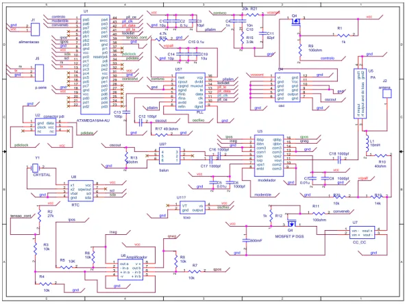
As mentioned in section1.2, our beacon, in its most simplified form, will consist of a micro-controller that will command the rest of the circuit and process the data sent by a GPS through a serial port. There will also be an frequency generator that will provide a constant frequency of 401.65MHz to an I/Q modulator. The signal that will be returned by the modulator will go through an RF power amplifier that will amplify the signal to get an expected output power of 2 Watt during transmission. Finally, the circuit will have an antenna to radiate the signal.
This layout can be seen in a simplified form in figure3.1.
It is also necessary to note that the final circuit is more complex than the one shown in figure 3.1, as can be seen in figure 3.12, due to the fact that the circuit has to fulfill the needs of the chosen components.
This topology has been adopted to address the problem because this solution better implement the objective of the beacon. Being the level of energy consumption a critical aspect, it is possible to verify that it would not make much sense to have a microcontroller with a built-in I/Q modulator, since the microcontroller will be used for longer periods than the modulator (there would be an unnecessary power consumption). Therefore this topology enables us to shut down most of the devices when they are not being used, in order to save energy.
24 Dimensioning of the Beacon Microcontroller and DAC Inputs Oscilator I/Q modulator Enable Enable I Q Power Amplifier Antenna Enable
Figure 3.1: Simplified architecture of the proposed solution
Moreover, we want to send data over short periods of time, reinforcing the idea previously presented.
Another reason why this topology has been adopted is the fact that all components that consti-tute the beacon are SMD (Surface Mount Devices) which facilitates their integration into a small size PCB. Finally, these components are relative well know, having already been used before.
3.2
Choice of the Components
At this point we will start by choosing the microcontroller, taking the needs of the beacon into account. Since it is necessary to generate two distinct analog signals to drive to enter the I/Q modulator it is necessary that the microcontroller has at least two DACs (Digital to Analog Converter). The DAC’s should have a good resolution, so 12 bits resolution was chosen.
Another important aspect that must be taken into account, is energy consumption. It should be as small as possible, therefore it is better to use a microcontroller with a low supply voltage.
Finally, the circuit will be in standby mode during certain periods of time to conserve battery power. Due to this, factor it is necessary that the microcontroller has a small wake-up time in order to allow it to react within the desired time.
Table 3.1: Microcontrollers characteristics
Parameters Atxmega16A4 [18] ADuC7026 [19] MSP430F123 [20]
Vcc 3.3V to 3.6V 3.6V 1.8 V to 3.6 V
Icc per I/O 20mA 45mA 200 µA at 1 MHz at 2.2 V
Wake-up time 0.17 µs 3 µs 6 µs
DAC’s resolution 12 bit 12-bit N/A
SRAM 3.3KB 8kB 8KB
As can be seen in table3.1the MSP430F123 has no internal DAC, which taking into account the presented solutions makes it no longer a valid option for the microcontroller. The Atxmega 16A4 has a lower power consumption than ADuC7026 which indicates that it will be a better option for our circuit. We can also verify that the first microcontroller has a much lower wake-up time than the second.
3.2 Choice of the Components 25
It is worth noting that the two DAC have the same resolution and the only advantage provided by the ADuC7026 relatively to Atxmega 16A4 is a larger SRAM size. For our case the ATxemga SRAM memory is enough. So taking into account all the factors discussed above we can choose the Atxmega.
Another of the components to be chosen is the local oscillator whose frequency has a fixed value of 401.65MHz. The frequency has to be stable, as discussed in section2.2.4. Because of this, the most viable solution was an oscillator that could be controlled by voltage.
Therefore have been found two oscillators that met our constraints. One is the CVCO33Cl [21] and the other is the CVCO55BE [22]. What differs between the two oscillators is the fre-quency range that each one provides. The CVCO33CL has a frefre-quency of 400 to 440MHz and the CVCO55BE has a frequency range of [400 to 800MHZ], as observed in table3.2. We can verify that the CVCO55BE has a bigger power consumption than the CVCO33CL.
Table 3.2: Characteristics of the oscillators Parameters CVC033CL [21] CVC055BE [22]
Vcc 3.3V 5V
Icc 16mA 17mA
Load Impedance 50 Ω 50 Ω
Frequency Range 400-440MHz 400-800MHz
Given the fact that the frequency is located at 401.65MHz, the two selected oscillators meet this requirement. Therefore the fact that the CVCO33Cl has a lower power consumption than CVCO55BE, elects it to be part of the beacon.
To obtain a stable frequency at the oscillator output, a control system has been designed with a PLL (Phase Locked Loop). The design of this control system will be presented later ahead in section3.3.2.
In order to reduce the power consumption of the beacon, this oscillator only has to be active during the transmission of messages to the ARGOS satellite. Consequently, a switch made with a MOSFET (Metal Oxide Semiconductor Field Effect Transistor) will be placed in his power supply in order to turn it on when necessary. The design of this switch will be presented in section3.3.1. As indicated in figure3.1, the I/Q modulator is the third component of the circuit. This com-ponent picks up the waves I and Q, which are given by the microcontroller DAC and, use them to modulate te 401.65MHz signal from the oscillator. This microcontroller has only one DAC but since it has the possibility to sample and hold it can produce two outputs with a DAC, loosing a bit of the sampling frequency. This waveform is already in the Manchester PSK +/- 60 degrees coding. So the next step is the choice of the I/Q modulator.
This component should have a power supply of 3.3V and should have a range of frequencies that allows it to operate at the frequency of 401.65MHz. After a search by several manufacturers, two devices were found at Analog Devices as can be seen in figure3.2.
As can be seen from figure3.2, both the AD8345 [23] and the AD8346 [24] have the same power supply operating at 3.3V. Although one of the central concerns is to reduce the circuit
26 Dimensioning of the Beacon
Figure 3.2: Characteristics of the modulators
consumption, as we can verify the AD8346 minimum RF frequency is well above the intended for the beacon. Although the AD8346 has a lower power consumption, the chosen modulator will be the AD8345.
This modulator provides an output signal with 1mW which be important to define our RF power amplifier because we need an output power of 2W. This automatically implies that our amplifier should have a gain of 2000, approximately 33dB.
Subsequently, and taking into account the facts set before, we proceed to the choice of the RF power amplifier.
In the choice of the amplifier, our main condition is that it needs top provide a gain of 33dB. So the surveys of possible solutions has been oriented to the desired gain. It was found an amplifier that meets the range of frequencies where it has to work and has a gain of 32.5 dB which is quite close to the intended. In table3.3, we can see the amplifier electrical characteristics. From here we see that the amplifier needs to be supplied with a minimum voltage of 6.2V.
Table 3.3: Characteristics of the power amplifier Parameters MSA-0886-BLKG [8] Vcc 6.2V to 9.4V Id 65mA Load Impedance 50 Ω Frequency Range 0.1 to 3GHz Gain 32.5 dB
Being the beacon powered at a voltage of 3.3V and since the amplifiers require a power supply between 6.2V to 9.4V a problem arises. To solve this situation, the adopted solution was to use a DC/DC converter to increase the voltage from 3.3V to the desired value. In this case that voltage will be 12V, since the amplifier requires at least 10V in order to have an operating voltage of 7.8V as shown in figure3.3.
Looking at figure3.3, and using the data of table3.3, we can easily conclude the value of that Rbias resistance. The value is calculated as follows:
Rbias=V cc−V d
Id ⇐⇒ Rbias =
10V − 7.8V
65mA = 33.8Ω (3.1)
Since it is difficult to find a resistor of 33.8 Ω a 40 Ω resistor was chosen, which means that the Vd value will be 7.4V, still within the operating voltages.
3.3 Choice and sizing of the remaining components 27
Figure 3.3: Power amplifier - typical configuration[8]
So, to provide these 10V of power supply to the amplifier an IE0312S-H [25] was chosen rising the voltage from 3.3V to 12V.
After choosing all the components for the adopted topology, the antenna was selected. This antenna must have an operating frequency that allows the operation on 401.65MHz and an input impedance of 50 Ω. Since it will be embedded in the PCB the antenna dimensions should be as small as possible. Two options were found as shown in the table3.4.
Table 3.4: Characteristics of the Antennas
Parameters CAN4311129200431K [26] CAN4313121200431B [27] Working Frequency 400MHz to 500MHz 400MHz to 500MHz
Bandwidth 20MHz 20MHz
Impedance 50 Ω 50 Ω
Dimensions 12mm * 4mm 37mm * 7mm
Gain 0.5dBi 0.5dBi
As can be seen by the data presented in the table, the two antennas have the same characteris-tics but the CAN4311129200431K is considerably smaller so it was chosen.
3.3
Choice and sizing of the remaining components
After starting the choice procedure of components that will integrate the beacon it is necessary to understand that alone they would not work. It is necessary to design the control system as well as the interfaces between them. So, below the entire design of the components and the control system for the circuit is presented.
3.3.1 Switches
As mentioned earlier, the component choice took the reduction of power consumption into consideration. Please note that, from all the components that were chosen, only four do not have a
28 Dimensioning of the Beacon
chip enable signal. This signal allows to activate and deactivate specific components. One of this components is the opamp. This component has a current in the order of pico Ampere, so it will be discarded because its power consumption is very low.
Still, the VCO, the DC/DC converter and the power amplifier operational state need to be controlled. A way to control the operation of these components is to introduce a switch in their power supply and allowing switching on and off the components.
For this propose a PNP MOSFET will be used. As the DC/DC converter is used to supply the power amplifier it is obvious that controlling the operation of the converter we can also control the operation of the power amplifier. This allows a reduction in the number of MosFets used.
In this section the switch for the VCO will be dimensioned and the other for the CC/CC converter will be dimensioned in section3.3.5. However, the MosFet chosen for this switch is the same for the switch to control the converter.
Since this MosFet will lead the voltage from the source to the drain, a survey was made looking for one that had the smallest voltage drop when in triode state, that is the lower Vds.
Taking into account this restriction and after performing a survey the NTR2101P MOSFET [9] was chosen, which has a Vds lower than 300mV. By analysis of figure3.4, is possible to see that for a Vgs of 3.3V and a 500mA Idmax, the Vds drop is less than 300mV.
Figure 3.4: Id vs Vds [9]
The topology adopted for this switch can be seen in figure3.5.
Next, the values of R1 and R2 resistors will be determined in order to make the MosFet behave like a switch. It should be noted that its gate is connected to the microcontroller.
The R1 resistance will have a value of 100Ω. This resistance limits the current peak in the gate, so that by varying the gate voltage, the current that goes through the gate capacitor does not tend to infinity. Normally these gate resistances are small. The resistance R2 will have a value of 1KΩ. This is a normal pull-up resistor.
3.3 Choice and sizing of the remaining components 29
Figure 3.5: MosFet as a Switch
3.3.2 Oscilator Control
Since the VCO is a voltage controlled oscillator it is necessary to introduce a specified voltage to obtain a specified frequency. As in this case the frequency should be as stable as possible, a solution that could dynamically adjust the control voltage of the VCO was chosen in order to stabilize as possible the frequency generated.
In order to achieve this frequency stability a PLL was introduced in the beacon. A search was made for PLLs that support the frequency of 401.65MHz and have an operating voltage of 3.3V. The TRF3750 [10] PLL was chosen.
The PLL is a device that compares the phase of an input frequency divided by a R factor with the phase of the output frequency of the VCO in order to generate a charge pump voltage. This voltage is the VCO control voltage. The operation of the PLL can be easily understood through the analysis of its functional block diagram, that can be observed in figure3.6.
As we can see from the figure, the signal from the input oscillator is divided by a R value that is defined in the PLL programming phase as well as the prescaler, the A and B registers. The output signal of the VCO passes through the prescaler register where its frequency is divided by the value of this registry. This frequency should not exceed 200MHz which is the operation limit of the PLL.
Finally, the signals are injected into this Phase Frequency Detector (PFD) which as the name suggests, compares the two signals in terms of frequency and phase and by adjusting the voltage of the charge pump making this coincide and leading to the desired frequency.
The basic configuration of the PLL that is available in its datasheet and which is in figure3.7 was adopted. The capacitors and resistors values available into that example were used. Addition-ally 1KΩ resistors were placed, on the programming pin of the PLL for pull-up to ensure that it has the correct voltage to read a logical one.
To complete the PLL circuits it should be noted that this device has a charge pump voltage (VCP), that needs to be at least 1V greater than the power supply. Since Vcc is 3.3V this means that the VCP is at least 4.3V.
30 Dimensioning of the Beacon
Figure 3.6: Functional block diagram [10]
Figure 3.7: Tipical PLL configuration [10]
In the case of our beacon this voltage can only be provided by the DC/DC converter. It was decided that the VCP voltage would be 5V and this way the circuit shown in figure3.8has been adopted, to ensure that voltage.
The zener diode was placed in the circuit for providing the function of voltage regulator to obtain a voltage as close as possible to 5V. The chosen zener diode was the BZX55C5V1 [28], having a maximum voltage of 5.1V and a Izk 1mA.
3.3 Choice and sizing of the remaining components 31
Figure 3.8: VCP power Supply
A preliminary test to the DC / DC converter was made in order to verify that it provides 10V when under load, after which an appropriated value for the resistance R1 was calculated as follows:
• Ir = 7.5mA + izk • Vcc = 10V • VCP = 5V
Using the following equation:
R1 =V cc−VCP
Ir =
10V − 5V
7.5mA + 1mA = 588Ω (3.2)
We obtain the value of the resistance R1 that is 588Ω. The value will be approximated to the standard value of 660Ω.
3.3.3 Dimensioning of the opamp as an inverter
This part of the circuit is responsible for inverting the signal that is generated by the DAC from the microcontroller. Since the I/Q modulator requires a differential for best operation, this circuit is needed.
A typical inverting configuration with an unitary gain was adopted, as shown in figure3.9. A search was performed for a single component that had two opamps and that worked at 3.3V. The AD8502ARJZ [29], fulfills such requirements.
The resistors R5, R6, R7 and R8 are part of the negative feedback loop that sets the gain. The gain is given by the expression:
Gain= −R f
R (3.3)
32 Dimensioning of the Beacon
Figure 3.9: Opamp - inverting configuration
The tensao cont voltage presented in the circuit provides a reference voltage to the microcon-troller DAC to optimize its functionality because it requires a reference voltage to work properly.
Being the desired voltage at this point of 1.4V obtained from 3.3V by a voltage divider com-posed by 20K(10K+10K) in series with R2, the latter is given by:
tensaocont= 20k
20k + R2∗V cc (3.4)
This expression gives a value of 27KΩ for R2. The detailed calculation is presented in ap-pendixA, sectionA.1.
Finally, the modulator requires that the waves have a DC component of 0.7V. Due to this fact the non inverting input will have a voltage of 0.7V to give that offset to the wave, to be obtained from tensaocont = 1.4V by the 10K+10K resistor divider.
3.3.4 I/Q modulator
One of the main components of the circuit is the I/Q modulator. It should receive a special attention because it makes the modulation of the signal to be sent.
According to the component datasheet it is possible to see that the modulator requires an average voltage of 0.7V at his differential inputs and a differential voltage of 200mVpp. The configuration used for this device can be observed in figure3.10.
Notice that there is a balun between the VCO output and the modulator input. This component is not anything more than a RF transformer with a ratio of 1:1. A search for a similar balun to the one that appears in the figure 3.10specified by the device datasheet led to the choice of the CX2156NL [30] balun.
3.3.5 Control system for the DC / DC converter
A significant part of the circuit, at the power level, is the DC/DC converter. This converter supplies the RF power amplifier and the PLL charge pump and for that reason it only needs to
![Figure 1.1: An example of an ERC. The radius of the capsule is approximately 5cm. [1]](https://thumb-eu.123doks.com/thumbv2/123dok_br/15713747.1069529/23.892.314.619.144.438/figure-example-erc-radius-capsule-approximately-cm.webp)
![Figure 2.2: Probability of reception by Argos-1 and 2 satellites vs. platform density [4]](https://thumb-eu.123doks.com/thumbv2/123dok_br/15713747.1069529/31.892.280.646.157.351/figure-probability-reception-argos-satellites-vs-platform-density.webp)
![Figure 2.3: Reception area of a signal for a satellite [5]](https://thumb-eu.123doks.com/thumbv2/123dok_br/15713747.1069529/33.892.276.659.142.530/figure-reception-area-of-signal-for-satellite.webp)
![Figure 2.4: Principle of location by the Doppler effect [5]](https://thumb-eu.123doks.com/thumbv2/123dok_br/15713747.1069529/34.892.234.617.265.643/figure-principle-location-doppler-effect.webp)
![Figure 2.5: The positioning based on Least squares analysis [5]](https://thumb-eu.123doks.com/thumbv2/123dok_br/15713747.1069529/35.892.277.660.145.416/figure-positioning-based-squares-analysis.webp)
![Figure 2.7: The RMC message [6]](https://thumb-eu.123doks.com/thumbv2/123dok_br/15713747.1069529/37.892.275.662.577.964/figure-the-rmc-message.webp)
![Figure 2.10: Example of a GPS phone tag device [7]](https://thumb-eu.123doks.com/thumbv2/123dok_br/15713747.1069529/40.892.232.618.131.667/figure-example-gps-phone-tag-device.webp)
![Figure 3.6: Functional block diagram [10]](https://thumb-eu.123doks.com/thumbv2/123dok_br/15713747.1069529/50.892.236.619.144.531/figure-functional-block-diagram.webp)