Jorge Miguel Sousa Barreiros
M.Sc.User-centric Product Derivation
in Software Product Lines
Dissertação para obtenção do Grau de Doutor em Informática
Orientadora : Professora Doutora Ana Maria Diniz Moreira,
Professora Associada, Universidade Nova de Lisboa
Júri:
Presidente: Prof. Dr. Nuno Manuel Robalo Correia
Arguentes: Prof. Dr. Alexander Egyed
Prof. Dr. João Carlos Pascoal Faria
Vogais: Prof. Dr. João Miguel Fernandes Prof. Dr. António Rito Silva
Prof. Dr. João Baptista da Silva Araújo Junior Prof.aDra. Ana Maria Diniz Moreira
User-centric Product Derivation
in Software Product Lines
Copyright © Jorge Miguel Sousa Barreiros, Faculdade de Ciências e Tecnologia, Universidade Nova de Lisboa
Agradecimentos
A obtenção do grau de Doutor é uma tarefa exigente, só tornada possível com a ajuda daqueles que nos são próximos. Por isso, é devido um agradecimento a todos os que me apoiaram nesta tarefa.
Não posso deixar de mencionar, em primeiro lugar, o Diogo e a Joana. Muito do tempo gasto neste trabalho foi-vos diretamente roubado. Por isso, ele é, em parte, tanto vosso como meu. Outra palavra especial vai para a Nanda, que foi a minha âncora ao longo destes anos. Estes agradecimentos especiais estendem-se a toda a minha família. Muito obrigado a todos!
Este trabalho também não teria sido possível sem a ajuda inestimável da minha orientadora, que alia, numa combinação rara e feliz, qualidades científicas, profis-sionais e humanas excecionais. Foi um verdadeiro privilégio trabalhar sob a sua supervisão. Muito obrigado pela sua disponibilidade, tempo, atenção e apoio incansável!
O meu apreço dirige-se também a todos aqueles que, de uma forma ou de outra, me ajudaram ao longo destes anos. São demasiados para enumerar, mas não fica esquecida a ajuda dos meus colegas de trabalho e do grupo de investi-gação, de todos aqueles que participaram nas minhas experiências de validação, e de todos os que contribuíram com observações, sugestões e críticas. Muito obri-gado e um enorme abraço coletivo a todos!
através das bolsas SFRH/BD/38808/2007 e SFRH/PROTEC/49834/2009. A to-das estas instituições, e aos seus responsáveis, os meus sinceros agradecimentos.
Obrigado a todos!
Abstract
Software Product Line (SPL) engineering aims at achieving efficient development of software products in a specific domain. New products are obtained via a pro-cess which entails creating a new configuration specifying the desired product’s features. This configuration must necessarily conform to a variability model, that describes the scope of the SPL, or else it is not viable. To ensure this, configuration tools are used that do not allow invalid configurations to be expressed.
A different concern, however, is making sure that a product addresses the stakeholders’ needs as best as possible. The stakeholders may not be experts on the domain, so they may have unrealistic expectations. Also, the scope of the SPL is determined not only by the domain but also by limitations of the development platforms. It is therefore possible that the desired set of features goes beyond what is possible to currently create with the SPL. This means that configuration tools should provide support not only for creating valid products, but also for improving satisfaction of user concerns.
We address this goal by providing a user-centric configuration process that offers suggestions during the configuration process, based on the use of soft con-straints, and identifying and explaining potential conflicts that may arise. Sug-gestions help mitigating stakeholder uncertainty and poor domain knowledge, by helping them address well known and desirable domain-related concerns. On the other hand, automated conflict identification and explanation helps the stake-holders to understand the trade-offs required for realizing their vision, allowing informed resolution of conflicts.
Additionally, we propose a prototype-based approach to configuration, that addresses the order-dependency issues by allowing the complete (or partial) spec-ification of the features in a single step. A subsequent resolution process will then identify possible repairs, or trade-offs, that may be required for viabilization.
ii
Resumo
O objectivo da engenharia de Linhas de Produtos de Software (do inglêsSoftware Product Lines, ou SPL) tem como objetivo o desenvolvimento eficiente de
produ-tos de software para um domínio específico. Produprodu-tos novos são obtidos através de um processo que obriga à criação de uma nova configuração, que descreve as características (em inglês,features) que devem ser integradas no produto. Esta
configuração deve necessariamente estar de acordo com um modelo de variabili-dade, que descreve o âmbito do SPL. Caso contrário, a configuração é inválida e não pode ser produzida. Sendo assim, para assegurar a viabilidade do produto, as ferramentas de configuração não permitem a especificação de configurações inválidas.
Uma questão distinta, no entanto, é assegurar que o produto que está a ser cri-ado serve os interesses dos utilizcri-adores (stakeholders, em inglês) tão bem quanto
possível. Os utilizadores não são necessariamente peritos no domínio, pelo que podem ter expectativas irrealistas. Para além disso, o âmbito do SPL é determi-nado não só pelo domínio em questão, mas também pelas limitações das platafor-mas de desenvolvimento. É por isso possível que um cliente deseje um produto que inclua um conjunto inadmissível de características. Isto significa que, para além de se preocupar com questões de validade, as ferramentas de configuração deverão também oferecer apoio direcionado para promover a satisfação dos uti-lizadores. Este apoio deve ajudá-los a fazer os compromissos necessários, de forma a obter uma solução exequível que satisfaz as suas necessidades tão bem quanto possível.
Propomos atingir este objetivo através de um processo de configuração cen-trado no utilizador, que oferece sugestões de configuração, e também identi-fica e explica eventuais conflitos. As sugestões ajudam a mitigar a falta de co-nhecimentos ou incerteza do utilizador, ajudando-o a atingir uma solução com
iv
propriedades desejáveis. Por outro lado, a identificação e explicação automa-tizada de conflitos ajuda o utilizador a melhor compreender os compromissos necessários para realizar a sua visão. Este apoio ao processo de configuração é conseguido através do uso de restrições suaves (em inglês,soft constraints), para
representar informação de variabilidade e restrições do utilizador.
Propomos também uma abordagem de configuração baseada em prototipagem, que ajuda a ultrapassar a dependência do resultado final em relação à ordem de configuração das características. Esta abordagem permite realizar a especifi-cação completa (or parcial) da configuração de várias características num único passo. Isto pode resultar numa configuração inválida, pelo que um processo sub-sequente irá identificar ações de reparação possíveis, que viabilizam da configu-ração pretendida.
Contents
1 Introduction 1
1.1 Objectives and Challenges . . . 2
1.2 Research Methodology . . . 6
1.3 Proposed Solution. . . 7
1.3.1 Configuration Advisor and Soft Constraints . . . 7
1.3.2 Prototype-based Configuration Approach . . . 9
1.3.3 Earlier Work . . . 9
1.4 Evaluation . . . 10
1.5 Contributions . . . 11
1.6 Structure of the Document . . . 11
2 Feature Modeling and Product Derivation 13 2.1 Software Product Lines . . . 13
2.2 Feature Models . . . 15
2.2.1 Boolean Logic Representation of Feature Models . . . 18
2.2.2 Feature Model Configuration . . . 19
2.3 Iterative Configuration of Feature Models . . . 20
2.4 Assisting the Decision Process . . . 23
3 Boolean Soft Constraints 25 3.1 Soft Constraints in Feature Modeling . . . 25
3.2 Boolean Soft Constraints in Feature Models . . . 26
3.3 Normative Semantics . . . 28
3.3.1 On Impossibility Functions . . . 31
3.3.2 Annotation of a Feature Model with Normative Soft Con-straints . . . 34
vi CONTENTS
3.4 Annotational Semantics . . . 34
3.5 Conclusions . . . 35
4 Soft Constraints in Domain Engineering 37 4.1 Domain-related Soft Constraints . . . 37
4.2 Prototypical Applications . . . 40
4.2.1 Soft Constraint Annotation Patterns . . . 40
4.2.2 Optional Selection Suggestion . . . 40
4.2.3 Reversed Constraint Suggestion . . . 41
4.2.4 Group Selection Suggestion . . . 42
4.2.5 Soft Constraints and Feature Model Evolution . . . 43
4.3 Suspicious Soft Constraint Interactions. . . 45
4.3.1 Suspicious Interaction Classification . . . 46
4.3.2 Identification of Suspicious Interactions . . . 48
4.4 Conclusions . . . 52
5 Enhanced Configuration Support 55 5.1 Enhanced Support Overview . . . 55
5.1.1 Configuration Suggestions . . . 56
5.1.2 Conflict Identification and Explanation . . . 57
5.2 Algorithms for Configuration Advice and Conflict Analysis . . . . 60
5.3 Tool Description . . . 63
5.4 Conclusions . . . 66
6 Prototype-Based Configuration 69 6.1 Prototype-based vs. Iterative Configuration . . . 70
6.2 Configuration Repair Overview . . . 75
6.3 Configuration Repair Based on Cover Information . . . 76
6.3.1 Cover and Literal Minimization . . . 77
6.3.2 Feature Model Partioning for Efficient Cover Computation . 77 6.3.3 Configuration Repair Using Cover Information . . . 80
6.3.4 Performance and Optimality . . . 83
6.3.5 Selection Criteria . . . 84
6.3.6 Repair of Partitioned Feature Models . . . 84
6.4 Presentation of Potential Repairs . . . 87
6.5 Tool Description . . . 88
CONTENTS vii
7 Validation 93
7.1 Identification of Suspicious Interactions . . . 94
7.1.1 Experiment Objectives and Goals. . . 94
7.1.2 Data Set Construction and Constraint Injection . . . 95
7.1.3 Unsatisfiable and Untriggerable Soft Constraint Identifica-tion Experiment . . . 99
7.1.4 Contradictory Soft Constraint Identification Experiment . . 100
7.2 Configuration Repair Testing . . . 103
7.2.1 Experiment Objectives and Goals. . . 103
7.2.2 Partitioning and Cover computation . . . 105
7.2.3 Repairing Random Invalid Configurations . . . 109
7.2.4 Problem Decomposition . . . 114
7.3 Empirical Testing of Enhanced Configuration Support . . . 115
7.3.1 Experiment Design . . . 115
7.3.2 Data Analysis and Hypothesis . . . 117
7.3.3 Experiment Realization . . . 119
7.3.4 Statistical Analysis of Results . . . 119
7.3.5 User Feedback . . . 121
7.4 Results Discussion . . . 124
7.4.1 Identification of Suspicious Interactions . . . 124
7.4.2 Configuration Repair Testing . . . 125
7.4.3 Empirical Testing of Enhanced Configuration Support . . . 127
7.5 Threats to Validity. . . 128
8 Conclusions and Future Work 131 8.1 Research Questions Revisited . . . 131
8.1.1 How to leverage the use soft constraints in SPL develop-ment to achieve this goal? . . . 132
8.1.2 How to provide enhanced configuration support? . . . 133
8.1.3 How to represent the user’s idealized configuration? . . . . 135
8.1.4 How effective is enhanced configuration support? . . . 137
8.1.5 How efficient is enhanced configuration support? . . . 137
8.2 Past, Present, and Future . . . 138
8.2.1 The Past . . . 138
8.2.2 The Present . . . 140
8.2.3 The Future . . . 141
viii CONTENTS
A Earlier Work 157
A.1 Graphical Representation of Configuration Knowledge . . . 157
A.2 Reusable Model Slices . . . 162
A.2.1 Overview . . . 162
A.2.2 Wildcards . . . 163
A.2.3 Default values . . . 163
A.2.4 Operations . . . 163
A.2.5 Instantiation . . . 164
B Box and Whiskers Plots 167 B.1 Box and Whiskers Plots . . . 167
C Validation Results 171
D GQM Document 179
List of Figures
1.1 From stakeholder wishes to an implementable configuration . . . . 3
1.2 Configuration advisor . . . 8
2.1 Feature tree elements . . . 17
2.2 Mobile phone feature model . . . 18
2.3 Example of BDD and its use for configuration purposes. . . 21
2.4 Feature model for configuration example . . . 21
3.1 Normative soft constraints example (the key describes the con-densed variable notation used in the text) . . . 30
3.2 Complex Normative Constraint Example . . . 32
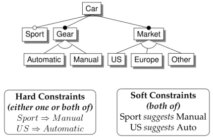
4.1 Feature model describing vehicles configuration . . . 39
4.2 Example of Optional Selection Suggestion . . . 41
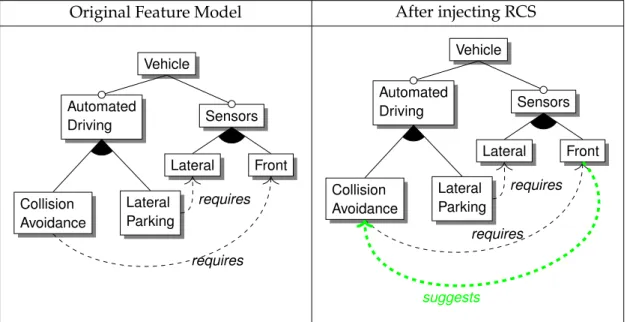
4.3 Example of Reverse Constraint Suggestion . . . 42
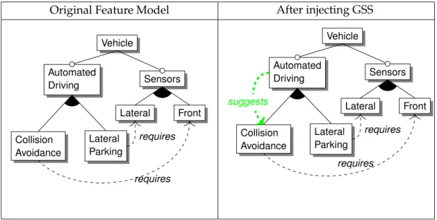
4.4 Example of Group Selection Suggestion . . . 43
4.5 Evolving a feature model via soft constraints . . . 44
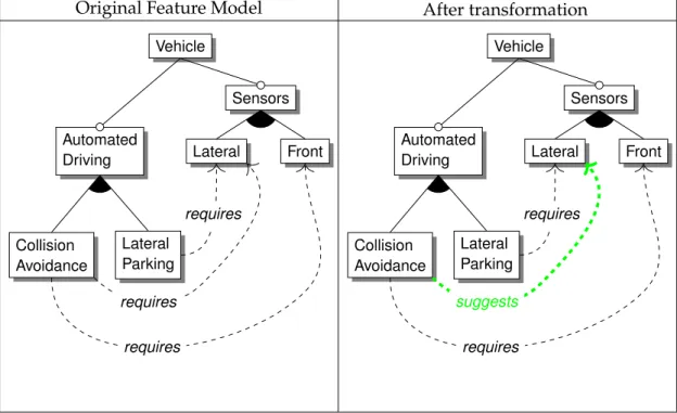
4.6 Restructuring the feature tree via soft constraints . . . 45
4.7 Unsatisfiable soft constraint example . . . 46
4.8 Contradictory soft constraints . . . 46
4.9 Untriggerable soft constraint Example . . . 47
5.1 Enhanced configuration support example . . . 58
5.2 Features conflicted due to multiple constraints . . . 59
5.3 Configurator tool packages . . . 64
5.4 Configurator tool - Experiment test case . . . 65
6.1 Feature model and idealized configuration . . . 71
x LIST OF FIGURES
6.2 Order-dependent outcome in iterative configuration . . . 72
6.3 Prototype configuration . . . 72
6.4 Configuration repair example . . . 75
6.5 Feature model decomposition example. . . 78
6.6 Feature model decomposition example - Step 1 . . . 78
6.7 Feature model decomposition example - Step 2 . . . 79
6.8 Feature model decomposition example - Step 3 . . . 80
6.9 Feature model for example of repair extraction from cover terms. . 81
6.10 Invalid configuration . . . 82
6.11 Configuration repair tool in action . . . 89
7.1 Analysis time per constraint . . . 101
7.2 Analysis time per feature model . . . 102
7.3 Percentage of contradictory pairs . . . 104
7.4 Analysis time for all contradictions with one specific constraint [ms]105 7.5 Analysis time of a pair of constraints [ms] . . . 106
7.6 Ratio between the number of terms after partitioning and before partitioning (TP/TF) (outliers not represented) . . . 108
7.7 Time required for execution of partitioning algorithm . . . 110
7.8 Time to find first repair (ms). Outliers not represented. . . 112
7.9 Academic and industrial experience of participants (some partici-pants are not represented as they chose not to provide the corre-sponding optional information). . . 120
7.10 Self-assessment of participant competence. . . 120
7.11 Feedback results, describing participant perception of efficiency and effectiveness gains, as well as helpfulness of trade-off infor-mation. . . 122
A.1 Media application example . . . 157
A.2 Configuration module . . . 158
A.3 Association describing configuration flow and cardinality constraints159 A.4 Composition example . . . 159
A.5 Specialization example . . . 160
A.6 Association describing constraint only, without any configuration flow. . . 160
A.7 n-Ary association to represent complex constraint . . . 161
A.8 Representing alternative implementations with specializations. . . 161
LIST OF FIGURES xi
A.10 Resulting MATA transformations . . . 166
List of Tables
2.1 Feature model transformation into Boolean propositional logic . . . 18 2.2 Feature model transformation example . . . 19
3.1 Boolean soft constraints . . . 27 3.2 Normative constraint example results . . . 30
7.1 Feature models included in input data set. . . 96 7.2 Injection results . . . 99 7.3 Aggregated results for unsatisfiable and untriggerable soft
con-straint identification . . . 100 7.4 Extract of the results for largest models . . . 107 7.5 Partitioning - Outlier cases . . . 109 7.6 Repair of random configurations — excerpt of full results . . . 111 7.7 Extract from repair results — Finding repairs for invalid
configu-rations that preserve selected features . . . 113 7.8 Problem decomposition of repairs of random configurations. . . 114 7.9 Feature models selected for test cases. . . 117 7.10 Statistics for self-assessment of participant competence . . . 121 7.11 Agregated feedback results . . . 122
C.1 Results for soft constraint injection . . . 172 C.2 Results for identification of untriggerable and unsatisfiable soft
constraints . . . 173 C.3 Results for identification of contradictory pairs of soft constraints . 174 C.4 Partitioning and cover extraction results . . . 175 C.5 Repair results - Finding repairs that minimize Hamming distance
from random invalid configurations. . . 176
xiv LIST OF TABLES
List of Algorithms
1 Suggestion computation . . . 60 2 Active feature computation . . . 61 3 Analize inconsistency . . . 62
4 Partition feature tree . . . 79 5 Computing a candidate repair from a specific term . . . 82 6 Computing all candidate repairs . . . 83
7 Soft constraint injection algorithm . . . 98
Glossary
Application Engineering: In software product lineengineering [Cle01,PBL05], it is the process by which a customized product is developed by creating a valid configurationoffeatures, composing reusable core assets and developing what-ever application-specific assets may be required. This process is conducted by the Application Engineer.
Configuration: In software product line engineering [Cle01, PBL05], it is a set of selected and deselectedfeatures[KKL+98]. If a configuration conforms to the
feature model, it is said to bevalid, otherwise it isinvalid. Apartialconfiguration
is one not yet complete, hence including openfeatures(that are not yet selected or deselected). A valid configuration corresponds to one of the specific products that may be created by thesoftware product line.
Constraint: Afeature modelmay include constraints, represented either graph-ically or textually [KKL+98, Bat05]. Typically, these are
hard constraints, that
must be upheld in all valid products. Alternatively, some constraints may besoft
[BM11,BDNRG10]. Soft constraints represent preferentialconfigurationoptions and, unlike hard constraints, do not necessarily impair validity of aconfiguration if not satisfied.
Domain Engineering: Insoftware product lineengineering [Cle01, PBL05], do-main engineering is the process by which the development platform is developed and maintained. The domain engineer defines the scope of thesoftware product line by defining the variability model. He is also responsible for creating and maintaining the reusable core assets.
xviii GLOSSARY
Feature: Features are composable artefacts that modularize modifications of un-derlying structures (program, architecture, requirements or other software devel-opment artefacts) satisfying some stakeholder’s needs. They are usually aligned with a user-visible aspect or characteristic of the domain [KKL+98,CHE05,Cle01,
PBL05,Bat06].
Feature Model: Feature models, introduced in [KKL+98], identify valid
prod-uct configurations by using an hierarchic feature tree describing optional and mandatoryfeatures, as well asfeaturegroups. They can be annotated with addi-tionalconstraints, represented graphically (e.g., linking dependentfeatureswith a dependency arrow) or by textual annotations. Feature models are frequently used in software product line engineering for identifying valid configurations corresponding to feasible products, or variants [KLD02,Cle01].
Software Product Line: Software product line engineering can be defined as a paradigm to develop software applications using platforms and mass customiza-tion [Cle01, PBL05]. A platform is, in this context, a software infrastructure that allows new software products to be efficiently developed and produced. Mass customization entails efficient tailoring and development of the software prod-ucts according to individualized client needs.
1
Introduction
Software users’ needs and desires change continuously. Unless specific provi-sions are made, keeping up with these evolving demands can entail considerable development efforts. Addressing evolution in a timely way with reasonable ef-fort is a major goal in Software Engineering. To achieve this, Software Product Line (SPL) engineering has been proposed [Cle01,PBL05,KLD02]. SPLs leverage planned reuse of development artifacts to allow for the timely development of alternative software products in a specific domain, in response to evolving users’ wishes.
Customized new products are created by a configuration process, which en-tails selecting the features to include and then composing the associated artefacts. Typically, not all combinations of features are viable: a description of common-ality and variability, usually in the form of a feature model [KCH+90], describes
valid configuration choices. The configuration process can be supported by au-tomated tools providing services such as configuration completion and choice propagation. These techniques ensure feasibility by allowing only valid products to be created.
However, little support is provided for helping the developer creating a prod-uct best meeting stakeholders’ needs. This is not a trivial task due to poten-tial misalignments between stakeholders’ desires and the capabilities of the SPL, manifested as restrictions on the admissible features that can integrate a product. Also, conflicting stakeholder wishes may exist. For example, if the intended con-figuration is specified by multiple stakeholders, conflicting specifications may be
2 CHAPTER 1. INTRODUCTION
created. Alternatively, even a single stakeholder may specify an invalid configu-ration if he does not have a clear comprehension of the domain or the limitations of the SPL. These conflicts need to be resolved somehow before an actual product can be created.
The issue is, then, finding ways to facilitate the creation of products that are the best possible match to the stakeholders’ desires. This is a complex problem that can be approached from different perspectives, such as SPL evolution (how to evolve the SPL to better accomodate user wishes), requirement engineering (how to elicit and model volatile and evolving user requirements), architecture definition (how to create a flexible architecture that efficiently supports all the re-quired variability and allows evolution), product preview and visualization tech-niques (how to provide feedback to the user so he has a clearer understanding of the product being created). Addressing such a diverse range of issues within the context of a single work is not feasible. For the sake of focusing our efforts, our approach is then concerned with providing mechanisms that assist the stake-holder (or a domain engineer on his behalf) during the product configuration process, attempting to ensure that the desired and actual configuration are as close as possible. While ideally these configurations would be identical, this is not always the case. The former can be perceived as a manifestation of the stake-holder’s desires, while the latter is a representation of a feasible product. In this way, dissimilarities correspond to required trade-offs or compromises.
The remainder of this chapter is structured as follows. Section1.1presents the objectives and challenges faced by our work. Section 1.2 discusses our research methodology, while Section 1.3 provides an overview of our proposed solution. Section 1.4concerns our approach to validate our results, and our contributions are enumerated in Section1.5. Section1.6presents the structure of this thesis.
1.1
Objectives and Challenges
Although SPLs reduce the time required to create variant products, an important question is to determine the features of the product that best match the stake-holder’s intention within the constraints of the variability model. Feature models have originally been proposed to represent a decomposition of system function-alities from a user’s perspective [KCH+90]. Within this paradigm, users’ desires
1.1. OBJECTIVES AND CHALLENGES 3
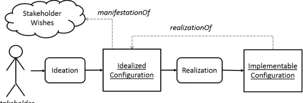
Figure 1.1: From stakeholder wishes to an implementable configuration
variability model of the the SPL. If the intended configuration is interpreted as an additional constraint applied to the feature model, then it may be the case that the product specification becomes overconstrained, making the users’ intended configuration unfeasible. So, in the general case, it cannot be ensured that all features may be selected according to the preferred users’ choices.
Figure 1.1 presents our model of the process that culminates with the cre-ation of a viable configurcre-ation corresponding to stakeholders’ wishes. As illus-trated, an implementable configuration is obtained only after a process where the stakeholders’ wishes are first codified into an idealized configuration1 (in a
pro-cess we designate as ideation), which is then subsequently transformed into an implementableconfiguration (that is, one that is viable, according to the variability
model) by therealizationprocess2.
Stakeholders do not necessarily have all the domain knowledge required to understand all the complexities and intricacies that impact on the feasibility of their desired product. This means that the idealized configuration may be un-feasible. For example, the stakeholder may wish a product that includes incom-patible features. These features may be incomincom-patible due to technicalities that are well outside his field of expertise. Alternatively, it may be a business-level decision from the SPL owner not to provide certain combinations of features, re-gardless of technical viability.
Conversely, stakeholders may also be unaware of some viable functionalities
1Whether or not such an artifact actually materializes or exists only as a mental construction in
the stakeholders’ (or application engineers’) mind is irrelevant to our discussion. Most frequently, SPL literature does not acknowledge this distinction and assumes that the implementable config-uration corresponds to a direct manifestation of stakeholders’ intentions.
2Although for simplicity sake we represent ideation and realization as sequential processes
4 CHAPTER 1. INTRODUCTION
that would be of their interest. These would not be included in the idealized configuration due to obliviousness, and therefore it would be sub-optimal. An example of a sub-optimality would be one where the stakeholder creates a con-figuration that does not fully exploit the potential of the system in ways that would be beneficial to him due to lack of domain expertise, like not including security enhancing features in a distributed multi-user system. Other example of sub-optimal idealization may happen when the stakeholder attempts to create a feasible idealized configuration, but has outdated knowledge of the SPL capabil-ities. He may, for instance, be unaware of new features that have been recently introduced, or of constraints that have been lifted. In this case, idealization may be polluted by ungrounded concerns of feasibility, as the stakeholder will ab-stain from using new features, or voluntarily force himself to respect obsolete constraints that no longer actually apply.
This means that any idealized configuration may be both unfeasible and sub-optimal. That is, the output of the ideation process (the idealized configuration) may not accurately reflect the stakeholder’s wishes, and it may also be invalid. If the idealized configuration is not valid, the ensuing realization process will trans-form it into a configuration that is actually implementable. The realization pro-cess involves sanitizing inconsistencies in the idealized configuration to obtain a new valid configuration, that is as "close" as possible to the idealized configura-tion.
The intermediation of an application engineer (the role of the developer in charge of creating a specific product, see Section 2.1), does not make these dif-ficulties disappear: although the application engineer is most likely fairly con-versant with the variability model and the possibilities and boundaries of the SPL, resolution of incompatibilities is a challenging problem that ultimately re-quires stakeholder intervention. Taking advantage of untapped possibilities is also problematic, as the application engineer would have to discern if some of the unsolicited functionalities would actually be of use or interesting for the stake-holder (again stakestake-holder intervention would still be ultimately required). In this way, for convenience we henceforth refer only to the stakeholder (or simply "user" for convenience) as having an active role during the configuration process, with the understanding that the application engineer might also play a more or less significant part in the process.
1.1. OBJECTIVES AND CHALLENGES 5
is important that our approach does not presume that the stakeholder is a domain expert. We must therefore seek ways to overcome these challenges without overly relying on stakeholder’s expertise.
These problems may be summarized in two points:
• The idealized configuration may be sub-optimal. This means that it does not reflect the stakeholders wishes as accurately as possible.
• The idealized configuration may be unfeasible. It is necessary to deviate from the idealized configurations, and trade-off decisions are most likely necessary.
Sub-optimality is related to deviation from preferential configuration options, while unfeasability can be traced to overconstrainment. Soft constraints are a
prime candidate for representing both preferencial and overconstrained configu-rations, and will therefore play a significant role in our solutions.
Assuming a relatively uninformed stakeholder is in question, these issues can be synthesized into the following main research question
How to support the derivation of software products in SPL that best conform to stakeholders’ goals?
which can be sub-divided into the following questions
1. How to leverage the use soft constraints in SPL development to achieve this goal?
(a) How to use soft constraints in the domain engineering step?
i. How can suspicious soft constraint interactions be efficiently iden-tified and reported to the domain engineer?
ii. How common are these interactions?
(b) How to use soft constraints in the application engineering step?
2. How to provide enhanced configuration support?
3. How to allow users to model, and inform the system, their idealized con-figuration, so that automated support can be given?
6 CHAPTER 1. INTRODUCTION
(b) How to properly address the large number of potential trade-offs that may be possible, without overwhelming the user with a very large number of alternative possibilities?
4. How effective is enhanced configuration support?
5. How efficient is enhanced configuration support?
These research questions are revisited and discussed in the light of the content of the next chapters in Section8.1.
1.2
Research Methodology
Our approach was based on the Technology Research method [SS07]. This method entails the production of new or improved technological artefacts to address a specific need. These artefacts are then demonstrated to be suitable for their pur-spose. The main steps of this process are:
1. Problem Analysis. Where the researcher identifies the potential need for new or improved technological artefacts. Based on the literature review and the analysis of existing approaches for SPL, we identified the problems and challenges discussed in Section1.1.
2. Innovation. Where the researcher explains how to make an artifact that sat-isfies the needs identified in the problem analysis step, and creates it. After having identified the main problem areas, we began identifying some possi-ble ways of addressing them. This resulted in the publication of some early work (Section 1.3.3). Feedback from review and presentation was used to further develop our approach, finally resulting in the solutions presented in Sections1.3.1and1.3.2and described throughout chapters3to6. Prototype tools were created to support the validation efforts.
1.3. PROPOSED SOLUTION 7
1.3
Proposed Solution
Our solution addresses the research questions highlighted in Section1.1. The first sub-question (question 1) is concerned with helping the user to derive the max-imum benefit from the SPL capabilities by ensuring his idealized configuration is not sub-optimal, that is, it does not miss out on potentially interesting features and configuration possibilities he might not be aware of. The next sub-questions (questions 2 and 3) are concerned with ensuring that the realization process facili-tates the creation of an implementable configuration that is close to the idealized, while ensuring the stakeholder understands the trade-offs required for validity sake and makes informed decisions. Research questions 4 and 5 make it clear that the proposed solution is expected to provide efficiency and effectiveness gains.
Our approach addresses these problems during therealizationstep (cf. Fig1.1).
Although the idealized configuration is already decided at this point (or at least part of it is: at minimum, the stakeholder must have decided to select or deselect just a single feature), during the realization phase it is possible to provide feed-back that allows the user to retroactively change and adapt the idealized configu-ration if necessary. We present two alternatives, suited for different configuconfigu-ration approaches. One of these alternatives is based on a configuration advisor and soft constraints, represented in Figure 1.2, while the other is a prototype-based configuration approach.
Earlier work developed by the authors proposed a graphical representation of configuration knowledge [BM09b], supported by an associated aspect-oriented modelling approach [BM09c].
1.3.1
Configuration Advisor and Soft Constraints
8 CHAPTER 1. INTRODUCTION
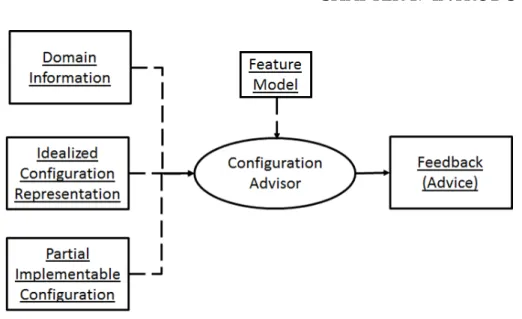
Figure 1.2: Configuration advisor
In a staged configuration approach, the implemented configuration will incre-mentally grow step-by-step. At each one of these steps, advice may be generated that is dependent on earlier choices made by the user. This advice is concerned only with the unspecified portion of the implemented configuration. That is, the advisor may suggest that some yet open (unspecified) feature should be selected. However, it will never advise changing the selection status of a feature that is already (de)selected.
Domain information, if available, is used to provide configuration suggestions that may cause the user to change his original intentions, that is, his intended configuration, to better take advantage of SPL capabilities. Referring to the dis-cussion in Section1.1, it is used to avoid or reduce sub-optimality. If an explicit representation of the idealized configuration exists, it may be provided to the ad-visor. The main purpose of this will be to use advisor feedback to identify and guide the stakeholder through potential trade-offs that must be made to realize an invalid idealized configuration.
One important question is determining what is the representation of idealized configuration and relevant domain information. The idealized selection state of each feature can then be represented by a soft constraint applied to the the
1.3. PROPOSED SOLUTION 9
process may prevent satisfaction of idealized preferences.
As a modeling tool, soft constraints can also be used to represent domain spe-cific information. For example, a soft constraint may be used to indicate that two features are commonly jointly selected, or that at least one of a certain set of fea-tures is usually selected. Using a similar modeling approach for both user prefer-ences and domain information allows an unified reasoning approach to address all cases.
1.3.2
Prototype-based Configuration Approach
While the advice-based approach is suitable for a staged configuration environ-ment, our prototype-based approach follows a different strategy. In this case, a representation of a complete or partial idealized configuration (the prototype) must be provided by the stakeholder. The system will then proceed to automat-ically identify and list what changes and trade-offs are necessary to ensure the prototype becomes viable (thereby transforming it into an implementable config-uration). These changes are presented to the stakeholder, who then has the re-sponsibility of selecting his preferred resolution among all possible alternatives. Like the advise-based strategy described in the previous section, protoype-based configuration ensures that the stakeholder is guided during the realization pro-cess. By finding and presenting to the stakeholder all possible alternative ways in which the prototype may be changed into a viable configuration, in accordance to an optimization criteria (usually the smallest distance from prototype to its realization in terms of Hamming distance [Ham50]), the developer is provided with a complete and fairly exhaustive list of alternative changes. By selecting and applying one of those alternatives, the stakeholder is implicitly resolving the trade-off as stipulated by the option he choses.
At the core of this approach, we find our cover-based configuration repair al-gorithm [BM14a], which is able to efficiently compute a large number of alterna-tive optimal repairs and present a condensed list of partitioned repair alternaalterna-tives of manageable size to the user.
1.3.3
Earlier Work
10 CHAPTER 1. INTRODUCTION
model components or source code files. This model describes how configuration information impacts the selection and configuration of features and their imple-mentation artefacts. It provides the graphical tools akin to a template-based ap-proach to configuration and implementation [CE00] by representing associations and specializations. However, it is not specific to any programming language or implementation technique. Additional capabilities are also provided such as the representation of complex configuration dependencies via n-ary associations or support for specifying the enumeration of parameter lists. The capabilities of this representation technique can be observed in sectionA.1of the appendices, where an example of one such model representing the configuration of a multimedia product is presented and described.
Another early work we developed proposes an aspect-oriented modeling tech-nique [BM09c]. It was designed to complement and support the work in [BM09b], by offering generic configurable aspects that can be instanced, using a simple language, into concrete MATA aspects [WJE+09], capable of advising correctly
diverse base models. See appendix A.2 for an overview of the proposed tech-nique.
1.4
Evaluation
1.5. CONTRIBUTIONS 11
actual human feedback to be considered for assessing the potential advantages of our work, in terms of efficiency and effectiveness of the configuration pro-cess. To conduct this experiment, we first identified the main objectives using a GQM document. Then, test cases were created and our prototype tool adapted to automatically submit test results. An online form was also made available for receiving user feedback. After a few adjustments based on an initial trial run feedback, several experiment sessions were conducted in two different locations. The experiment results were then subjected to statistical analysis.
1.5
Contributions
The main contributions of this work are:
1. Proposing and discussing the use of soft constraints throughout the SPL life-cycle, from domain analysis to product configuration [BM11,BM12] (Chap-ters3and4).
2. Identifying and describing certain types of potentially anomalous soft con-straint interactions, specifically unsatifiable, untriggerable and contradic-tory soft constraints [BM12] (Chapter4).
3. Providing mechanisms for automatically identifying and reporting these potentially anomalous interactions [BM12] (Chapter4).
4. Proposing an algorithm that leverages soft constraints to offer enhanced support during the configuration step, allowing increased satisfaction rates and better comprehension of required trade-offs [BM13, BM14b] (Chapter 5).
5. Devising a novel configuration repair mechanism, with very high perfor-mance and especially well suited for repairing multiple invalid configura-tions for the same feature model [BM14a] (Chapter6).
1.6
Structure of the Document
The remainder of this document is structured as follows:
12 CHAPTER 1. INTRODUCTION
• Chapter3,Soft Constraints in Feature Modeling. In this chapter, we define our soft constraint model. Two different semantic categories of soft con-straints are identified, and we discuss the suitability of each such category for our purposes.
• Chapter4,Soft Constraints in Domain Modeling. In this chapter, we iden-tify prototypical applications of soft constraints in the domain engineering step. These involve primarily the representation of domain information, but are also of use in feature model evolution.
• Chapter 5, Enhanced Configuration Support. In this chapter, we present our enhanced configuration support techniques based in soft constraints. We describe our advice generation and conflict detection algorithms, which are integrated into a incremental configurator to provide an enhanced con-figuration experience, and present our prototype configurator tool.
• Chapter 6, Prototype-based Configuration. In this chapter, we present a generalization of iterative configuration that allows the stakeholder to con-figure more than one feature simultaneously. Each such configuration step is then followed by an additional step where possible inconsistencies are detected and repaired.
• Chapter 7, Validation. In this chapter, we present the validation results. Results are based in publicly available feature models from online reposi-tories. We have conducted tests to assess the runtime performance of our algorithms, and an empirical test was also conducted.
2
Feature Modeling and Product
Derivation
Since their introduction over 20 years ago [KCH+90], feature models have been
recurrently used to represent variability in Software Product Line engineering [Cle01,PBL05,WL99,Par76]. Therefore, to clarify the context of our work and es-tablish technical bases, we present an overview of SPL engineering (Section2.1). Several variant feature models are also described, as well as the formalization and graphical representation of Boolean feature models (Section2.2). Product deriva-tion entails creating a configuraderiva-tion that conforms to the feature model (Secderiva-tion 2.3). This configuration determines the properties of the product, and as such is a manifestation of the stakeholder’s goals. Some techniques have been described to support the stakeholder in identifying the configuration that best satisfies those goals (Section2.4).
No original contributions can be found in this chapter, as its purpose is estab-lishing the required background for understanding later chapters.
2.1
Software Product Lines
One century ago, the adoption of assembly lines and pipelined manufacturing in the automotive industry heralded a new age in industrial manufacturing. It was a significant paradigm shift that eschewed earlier approaches in the search of
14 CHAPTER 2. FEATURE MODELING AND PRODUCT DERIVATION
higher labor efficiency and productivity. Dramatic improvements were immedi-ately observed, such as a nine-fold decrease in the time required to fully assemble a vehicle (from 12h30m down to 1h30m) [Hou85]. Since assembly lines excel at efficient production of high volumes of identical parts, product conceptualization and design also evolved accordingly. Improved tooling and production processes allowed finer precision and the creation of interconnectable, normalized and in-terchangeable parts. Consequently, rather than relying on custom-made compo-nents tailored specifically for a single specific product, the same parts were now being applied in the construction of a large number of different products [Hou85]. As a consequence, design and production efforts began focusing on product fam-ilies or lines rather than individual products.
The significant benefits obtained from the application of product line devel-opment in industrial manufacturing inspired the search for similar solutions in other domains. Software Product Line (SPL) engineering attempts to leverage the same principles to achieve similar benefits in software development. According to Pohl [PBL05], it can be defined as a paradigm to develop software applications using platforms and mass customization. A platform is, in this context, a software infrastructure that allows new software products to be efficiently developed and produced. Mass customization entails efficient tailoring and development of the software products according to individual client needs. To address both aspects, SPL engineering branches into two interdependent but separated processes. The first one, known asDomain Engineering, is responsible for establishing and
main-taining the platforms, while the second process,Application Engineering, concerns
derivation of the actual products, using the platforms, according to customized requirements of clients.
In the Domain Engineering step, many types of reusable software artifacts can be produced (code, models, documentation, tests, etc.). These assets are created with the specific purpose of supporting the efficient creation of software products within a specific domain. A very important result of the Domain Engineering activity is a model describing the variability and commonality of the realizable products. This variability model1implicitly defines the scope of the product line, that is, the full range of products that are meant to be produced by it. Typically,
feature models (Section 2.2) are used to represent variability [KCH+90, KCH+92,
KLD02,CE00].
1Although both commonality and variability are represented in this model, we will follow the
2.2. FEATURE MODELS 15
Application Engineering entails creating new products according to the spe-cific requirements of the clients. This is achieved by taking advantage of the plat-form developed in the Domain Engineering step. The process involves creating a new product configuration (Section 2.2.2), which describes, in conformity with
the variability model, the features of the desired product. This configuration is the basis for the selection and ensuing composition of the reusable assets in or-der to create the new product. Although ideally no additional development ef-fort should be required, it may be necessary to address specific functionalities or properties that are not directly achievable via composition of the reusable as-sets. The Application Engineer must then create theapplication assetscontaining
application-specific content. Still, the platform is expected to provide the means for efficiently creating the product, so additional product development effort be-yond configuration and composition of the base assets should be reduced. Appli-cation Engineering provides crucial feedback to Domain Engineering in the form of suggestions to develop support for new features. This process tends to migrate application assets into the core domain assets, so that they can be reused if nec-essary in new products or newer versions of the same product. In this way, the scope of the SPL evolves to accompany the needs of the clients.
2.2
Feature Models
Feature models are frequently used in SPL development for identifying configu-rations corresponding to products, or variants, that can be created by an applica-tion engineer using the SPL [KLD02,Cle01]. Indeed, feature models identify valid product configurations by using a feature tree annotated with additional domain constraints. These can be represented graphically (e.g., linking dependent fea-tures with a dependency arrow) or by textual annotations. In a SPL, products are characterized by the features they include. Typically, a feature modularizes an increment in functionality [KCH+90,Bat06], although non-functional features
may also be considered [KKL+98]. The presence of some features may be
16 CHAPTER 2. FEATURE MODELING AND PRODUCT DERIVATION
Basic feature models have been first described by Kang et. al in the Fea-ture Oriented Domain Analysis (FODA) report [KCH+90]. An hierarchical tree
model is used to represent mandatory, optional, and alternative relations be-tween features and their children. Additional constraints specifying crosstree dependencies can also be used, specifying the need for mutual exclusion or in-clusion between pairs of features. Later works allowed the generalization of constraints to arbitrary boolean propositions [Bat05]. Basic feature models have found widespread acceptance since their introduction, having been used in the context of generative programming [CE00], feature-oriented programming [Bat06], software factories [GSCK04] and model driven development [TBD07].
Extension and generalizations of basic feature models have been proposed. Cardinality-based feature models generalize feature models by allowing varying degrees of multiplicity when describing feature dependencies [CHE05, RBSP02]. These allow a feature to be selected multiple times, rather than being just in-cluded or exin-cluded from a product. Feature cardinality is an interval[m, n]that describes the number of times a child feature may be selected if its parent is also selected, where m is the lower bound andn the upper bound. For example, an
optional feature in the FODA model can be described as having cardinality[0,1],
while a mandatory feature can be described using the cardinality range [1,1].
Similarly, group cardinality dictates the number of children features that must be selected in each alternative group.
In extended (or attributed, or advanced) feature models, features include
at-tributes that provide additional information [KKL+98, Bat05, BBRC06, BTRC05,
SRI03]. These attributes are not restricted to boolean values, and represent impor-tant qualities such as cost or performance metrics, thereby allowing constraints of increased complexity to be expressed. Some configuration description languages originating from the operating systems domain such as kconfig [ZC] or CDL [VD01] allow the textual representation of extended feature model-like struc-tures, although options like embedded script coding can go beyond the scope of what is representable in feature models.
Since they were originally introduced, feature models have found applica-tions in many different domains such as telecom systems [GFD98, LKL02], tem-plate libraries [CE00], web services [RF03,LMN08], networking protocols [BB02], home automation [MRP+07], context-aware and mobile systems [MAW11] and
2.2. FEATURE MODELS 17
A
B
(a) Optional feature
A
B
(b) Mandatory feature
A
B C
(c) Or-Group
A
B C
(d) Alternative group
Figure 2.1: Feature tree elements
Regardless of the specific type of feature model being considered, the chal-lenges outlined in Chapter 1 are always relevant. Nevertheless, a specific type of feature model must be considered when devising the required configuration support algorithms. Due to their widespread acceptance and use, our work is therefore based on basic feature models. Whenever we refer to feature models, in the sequel, we refer to basic feature models unless otherwise noted.
Figure 2.1describes the graphical elements commonly used to construct fea-ture models. In Figure 2.1a, featureAis represented as having an optional sub-featureB, whereas in Figure 2.1b the subfeature is mandatory. Figure 2.1c and Figure 2.1d represent groups of features, known as OR-groups or Alternative-groups. Constraints can be represented graphically or textually. Well-known transformations, described in [Bat05,CW07], can be used to convert feature trees into Boolean logic expressions. A feature model expression is obtained by con-joining the feature tree expression with the domain constraints.
18 CHAPTER 2. FEATURE MODELING AND PRODUCT DERIVATION
Phone
MP3Player Sound
Polyphonic Monophonic
Keyboard Screen
Monochromatic Color Camera
requires
Figure 2.2: Mobile phone feature model
2.2.1
Boolean Logic Representation of Feature Models
Feature models can be represented using Boolean propositional logic. Each fea-ture is represented as a variable in the proposition and a set of well-known trans-formations is applied [Bat05, CW07] to obtain a Boolean proposition expression based on the topology of the feature tree and constraints. This expression will evaluate to⊤(true) for all valid configurations and⊥(false) for all invalid config-urations. The transformations are represented in Table2.1. The feature model
ex-Table 2.1: Feature model transformation into Boolean propositional logic
Feature Model Element Expression
root ⊤
A
B
B ⇒A
A
B
B ⇔A
A
B C D
A⇔(B∨C∨D)
A
B C D
B ⇔(A∧ ¬C∧ ¬D)∧
C ⇔(A∧ ¬B ∧ ¬D)∧
2.2. FEATURE MODELS 19
pression is obtained by conjoining the expressions obtained from aplication of the transformations in Table2.1 with all domain constraints. While the root feature can be modeled as⊤, it is convenient sometimes to ignore this to achieve homoge-nous treatment of all features (e.g., in feature model composition or refactoring, the root feature may change, so it can be convenient to have all features explicitly represented in the feature model expression). In this case, an additional Boolean variable corresponding to the root will appear in the feature model expression. However, this variable should be necessarily selected (most likely automatically) at the start of a new configuration process, to ensure that a void configuration is not deemed valid. Table 2.2 presents an example of the transformation of a feature model into an equivalent Boolean proposition.
Table 2.2: Feature model transformation example
Feature Model Transformation Root-preservingtransformation
A
B C D
E F
(⊤ ⇔B)∧ (C ⇒ ⊤)∧ (D⇒ ⊤)∧ (D⇔(E∨F))
(A⇔B)∧ (C ⇒A)∧ (D⇒A)∧ (D⇔(E∨F))
2.2.2
Feature Model Configuration
A configuration represents a specific product by describing the selected/deselected state of each available feature. A configuration is said to be validif it conforms
to the feature model structure and satisfies all (hard) constraints. Conformance is achieved by any configuration where:
• The root of the feature tree is selected
• All parents of selected subfeatures are selected
• All mandatory children of selected features are selected
• Exactly one subfeature is selected in each alternative group whose parent feature is selected
20 CHAPTER 2. FEATURE MODELING AND PRODUCT DERIVATION
• All domain constraints are satisfied
Useful feature models should always be consistent: a consistent feature model
allows at least one valid configuration. An example of a valid configuration for the feature model in Figure2.2is:
• Selected Features=[Phone, Sound, Keyboard, Screen, Camera, Polyphonic,
Color]
• Deselected Features=[MP3Player, Monophonic, Monochromatic]
A partial configuration is one where not all features are selected or deselected.
Those features are said to beopen.
2.3
Iterative Configuration of Feature Models
Iterative (or interactive, orstaged) configuration of feature models is a process by
which the Application Engineer creates a new product configuration by chosing to select or deselect a single open feature, in an iterative process, until all fea-tures are either selected or deselected [vdS04,Jan08,Bat05,CHE05]. Automated support for this process ensures that the choices are adequately propagated so that a valid configuration will always be obtained. To achieve this, common and dead features are automatically identified. The former are features that are al-ways selected in all valid configurations including the current partial configura-tion. Conversely, the latter are features that are always deselected in the same configuration. By automatically selecting common features and deselecting dead features after each configuration action of the user, configurators ensure that a valid solution is always obtained, as long as the feature model is not void. Both Binary Decision Diagrams (BDD) [Bry86,vdS04] and satisfiability (SAT) analysis [Jan08,Bat05] have been used for configuration of feature models.
BDD-based configurators identify common and dead features by verifying if nodes are always selected or deselected in all possible paths from the root down to the⊤leaf node.
2.3. ITERATIVE CONFIGURATION OF FEATURE MODELS 21
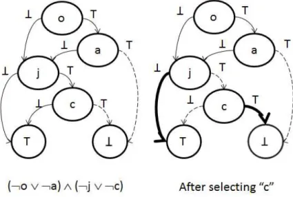
An example is provided in Figure 2.3. On the left side of the figure, a BDD
Figure 2.3: Example of BDD and its use for configuration purposes.
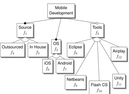
corresponding to the expression of the feature model in Figure2.4is shown (refer to the figure for the variable identification key). Starting from the top and
pro-Mobile Development
Other Android Java C++
excludes excludes
Key: o=Other a=Android j=Java c=C++
Figure 2.4: Feature model for configuration example
22 CHAPTER 2. FEATURE MODELING AND PRODUCT DERIVATION
the satisfiability of certain expressions. For example, given the feature model ex-pressionF(a, o, j, c), ifF(a, o, j, c)∧a is not satisfiable then "a" is a dead feature.
Conversely, if ¬SAT(F(a, o, j, c)∧ ¬a), then a is a common feature. Since
SAT-solvers can typically provide a variable assignment that satisfies the expression under analysis (if it is found to be satisfiable), then multiple results can be ob-tained with a single pass of SAT analysis. For example, if a variable "x" is selected in such an assignment, then the same assignment also satisfiesF(. . .)∧x.
Referring to the same scenario that is described in example in Figure2.3, after selection of "c", the possible configurations can be described by F(a, o, j, c)∧c.
The configurator will proceed by trying to identify common and dead features in the remaining unassigned variables (also referred to asopen features). Beginning,
for example, with feature "a", it will evaluateSAT(F(a, o, j, c)∧c∧a)to verify if it is dead. However, this expression is satisfiable by the assignment {j=⊥,o=⊥,c=⊤, a=⊤}, so that is not the case. Since j=⊥ in that expression, the same result also satisfiesF(a, o, j, c)∧c∧a∧ ¬j and, consequentlyF(a, o, j, c)∧c∧ ¬j, so "j" can
be found NOT to be common by the same result. Similar analysis can be made for "o". So, in a single pass of the SAT solver, the configurator is able to deter-mine that "a" is not dead, "j" is not common, and "o" is not common. Next, a new pass of the SAT solver would be used to assess if "a" is common, by computing
SAT(F(a, o, j, c)∧c∧ ¬a). The satisfying assignment {a=⊥, o=⊤, j=⊥, c=⊤} would
be found, from which it could be further determined that "a" is not common, "o" is not dead (and also that "j" is not common, though that is already established). "o" and "a" have already been found not to be neither dead nor common, so all that is left is to verify if "j" is dead. In fact, F(a, o, j, c)∧c∧j is not satisfiable,
2.4. ASSISTING THE DECISION PROCESS 23
2.4
Assisting the Decision Process
Regardless of the configuration technique used, the aim of the previous approaches is to steer the user into creating valid configurations. This is understandable, as all approaches are primarily based on information that describes only what valid configurations are. A different matter is helping the user to make decisions in the presence of multiple valid alternatives. Recommendator systems play such a role, and are used for advising a user who is selecting one product from a set of pre-existing alternatives [FJN+13,JZFF10,RRSK11], using both historical data
and domain-related heuristics. However, they do not address the issue of vari-able configuration of products, as they are concerned only with orienting the user in choosing one option from among a set of pre-existing solutions. The proba-bilistic feature models framework, described in [CSW08], is capable of orienting the user, during the configuration process, towards solutions that are correlated, from a frequency perspective, to the current partial configuration. While this is a most useful capability, dependencies between features that are not strictly related to frequency data are not easily addressed.
24 CHAPTER 2. FEATURE MODELING AND PRODUCT DERIVATION
The C20 configurator is presented in [NE13]. It is based on decision mod-els, that describe questions, possible answers, constraints and relevancy relations between those questions. The configurator supports the decision-making pro-cess, by guiding the user so that the number of questions to be answered is op-timized via an heuristic process [NE11], but allows the user to deviate and ex-plore inconsistent solutions, which must be fixed later in the configuration pro-cess. Although we do not attempt to minimize the number of required config-uration actions, this work addresses other concerns similar to our own, such as configuration-order issues and inconsistency handling, but there are some out-standing differences. In C20, soft constraints are not considered, so no domain-related advice is provided that helps addressing sub-optimal ideations. Choices are therefore always immediately propagated according to constraints and rel-evancy relations. These choices may be later changed by the user, entering an inconsistent state, that must be necessarily fixed in the sequel. We provide advice to the user that steers towards satisfaction of soft constraints and preemptively identifies choices that must be made to avoid conflicting features, but do not pro-pose the automated change of already configured features: either the conflict is inevitable or the user has deliberately decided to go against the configuration advice at an earlier point. Rather than allowing the configuration to enter an in-consistent state, we allow for inin-consistent specifications to be handled by upfront modeling of user goals as a set of (possibly inconsistent) soft constraints, or by resorting to prototype-based configuration (see Chapter6), where a complete (or partially complete) configuration can be specified as a single configuration step, which is then repaired if necessary to ensure validity is preserved.
Explanation-providing systems focus on identifying minimal sets of changes required for satisfying an overconstrained specification [Jun04,Rei87]. These ap-proaches are primarily based on the identification of minimal unsatisfiable cores. A minimal unsatisfiable core of a Boolean proposition in conjunctive normal form is a set of minimal dimension including the clauses that cannot be successfully satisfied (e.g.,¬A∧¬B∧(A∨B)). While many approaches for computing minimal
unsatisfiable cores exist [LS04], identification of the minimum (globally optimal)
3
Boolean Soft Constraints
A part of our proposed solution is the configuration advisor that offers additional support to the stakeholder during the configuration process. As illustrated in Fig-ure1.2, this advisor requires the use of soft constraints (SC) to represent domain information or stakeholders’ requirements. This chapter discusses different types of soft constraints applied to feature models, and investigates which semantics are most suitable for the purposes of our work.
We begin by presenting related work concerned with the use of soft con-straints in feature modeling (Section 3.1). Our original contributions discussed here are the Boolean soft constraints for feature models, the categorization of their semantics as normative or annotational (Section3.2), and the description of a framework enabling the use of normative constraints in feature models (Section 3.3). The role of annotational semantics is also discussed (Section3.4). The use of soft constraints in feature modeling relates with research question1, while using soft constraints to model overconstrained scenarios relates to research question 3a.
3.1
Soft Constraints in Feature Modeling
Soft constraints have been largely ignored in SPL development until recent years. Early efforts include [RP03], where a fuzzy logic description of costumer profiles
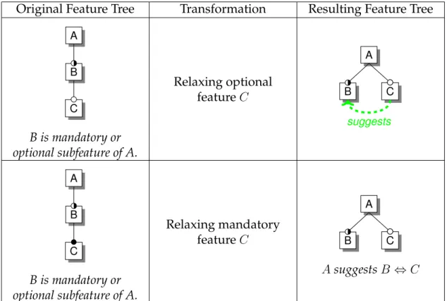
26 CHAPTER 3. BOOLEAN SOFT CONSTRAINTS
and domain constraints is added to feature models. "Encourages" and "discour-ages" constraints have been proposed for feature models in [WSO07]. However, these are used only to generate graphical decorations of the feature model: no precise semantics have been provided, precluding automated analysis and rea-soning as described in our work.
In [CSW08], Czarnecki et al. describe probabilistic feature models. In these, features can be related by a probability space (PSPACE) that describes probabil-ities of combined selection of features. This can be used to generate advice for steering the user into commonly selected feature configurations. Probabilistic feature models are well suited for representing the outcome of a feature min-ing process, by accurately representmin-ing observed frequencies. However, it can be challenging to represent domain information that is not directly related to fre-quency information (e.g., a suggestion to select a newly introduced feature).
In [BDNRG10], Bagheri et al. describe the use of fuzzy-based soft constraints to model stakeholder’s preferred configurations. A reasoning algorithm iden-tifies the optimal configuration that maximizes constraint satisfaction. This ap-proach differs from ours because it is concerned only with maximal constraint satisfaction. It does not address the question of trade-off identification and ex-planation nor is it concerned with the exploration of multiple alternative optimal solutions.
3.2
Boolean Soft Constraints in Feature Models
As a first step towards discussing the use of SCs in feature models, we first fo-cused our efforts in addressing the nature of soft constraints and explored possi-ble alternative semantics [BM11]. From early on, we decided to focus our efforts on Boolean soft constraints, even though fuzzy logic is more commonly consid-ered in the context of handling uncertainty and soft goals. This decision is based on the following considerations:
1. Standard feature models can be readily formalized as Boolean expressions [Bat05]. By using the same formalism, we can leverage a large body of re-search and tools already available.
3.2. BOOLEAN SOFT CONSTRAINTS IN FEATURE MODELS 27
3. The consequences and impact on results of the parametrization of a fuzzy-logic approach (e.g., fuzzification/defuzzification, selection of fuzzy opera-tors, etc.) may prove to be challenging to anticipate.
4. Other works [RP03, BDNRG10] had already begun exploring fuzzy-based approaches, so by exploring alternative solutions we believe a greater con-tribution may be offered.
Boolean SCs are described in Table3.1. They are represented by using one of four different binary operators applied to two Boolean propositionsP andQ. P
is said to be thetriggerof the soft constraint, whileQis theconsequence. Although
for completeness four different operators are represented, all constraints can be rewritten using only a single operator, as indicated in the second column of the table. Therefore, in the remaining text, we usually refer only to the first operator (suggests).
Table 3.1: Boolean soft constraints
Soft Constraint Equivalent to PsuggestsQ
-PdiscouragesQ Psuggests¬Q
Pabsence-suggestsQ ¬PsuggestsQ
Pabsence-discouragesQ ¬Psuggests¬Q
The following criterium is used to determine satisfaction of a soft constraint
The soft constraintP suggestsQis said to besatisfiediffP ⇒Q
A constraint is said to be triggered if its trigger P is ⊤ (true). Conversely, a constraint is untriggered if P is⊥ (false). A constraint is activated if Q is ⊤, and
inactivatedotherwise.