i
Faculdade de Engenharia da Universidade do Porto
An Approach to Simulation of Autonomous
Vehicles
Miguel Cordeiro Figueiredo
Dissertation executed under the
Integrated Master in Electrotechnical and Computer Engineering
Major in Telecommunications
Supervisor: Prof. Dr. Rosaldo Rossetti
Co-Supervisor: Prof. Dr. Luís Paulo Reis
ii
iii
Dedicated to
v
Abstract
The most common cause of traffic accidents is driver error. This isn't going to change any time soon thanks to increasingly cell-phone usage, in-car entertainment systems, and more traffic. Autonomous vehicles, like driverless cars, would decrease traffic accidents and traffic jams.
Automakers are currently developing systems that will enable these cars to do their role. Some of these systems are already widespread. For example, Anti-lock brakes, a standard feature in most cars, are a basic form of driverless technology. But there's still much work to do in the field of autonomous vehicles.
Simulations are safer, more efficient, and cheaper than live testing on vehicles. Changes have to meet a certain level of operation before they are put to a live test.
This thesis is about the study and implementation of a simulator to test such vehicles. Included is a study of the State-of-Art in driverless car simulations, and the objectives that such simulators should aim for in order to help test driverless car operations. Also included is an implementation strategy for such a simulator, and the software used for it, as well as modifications made to some software, and perspectives for future development.
vii
Resumo
A causa mais comum dos acidentes de trânsito é o erro do condutor. Isto não vai mudar tão cedo, graças ao crescente uso de telemóveis, uso de sistemas de entretenimento no interior do veículo e ao aumento do trânsito. Os veículos autónomos, tais como carros sem condutor, poderiam diminuir estes acidentes de trânsito e os engarrafamentos.
Os fabricantes de automóveis estão actualmente a desenvolver sistemas que permitem que esses veículos desempenhem o papel desejado. Alguns destes sistemas já estão amplamente difundidos. O da travagem anti-bloqueio, uma característica padrão na maioria dos automóveis, é um exemplo de uma forma básica dessa tecnologia. Mas há ainda muito trabalho a fazer no campo dos veículos autónomos.
Simulações são mais seguras, mais eficientes, e mais baratas do que testes ao vivo em veículos. Alterações nos veículos e no seu software devem chegar a um certo nível de qualidade antes de se fazerem testes ao vivo.
Esta dissertação é sobre o estudo e implementação de um simulador cujo propósito é testar estes veículos. Inclui uma panorâmica do desenvolvimento actual da área das simulações de carros autónomos e, também, os objectivos que estes simuladores devem tentar alcançar, a fim de ajudar a testar o funcionamento destes automóveis. Também está incluída uma estratégia de implementação para um simulador, o software utilizado, assim como as alterações feitas, e perspectivas para futuro desenvolvimento.
ix
Acknowledgments
Special thanks go to my family and friends for their unconditional support.
Especially to my sister Filipa for her help in the final stages of the dissertation. Without it, I don't think I'd have done this.
I'd also like to thank my supervisor, Prof. Dr. Rosaldo Rossetti, for assisting me with choosing the subject of my dissertation and for his understanding, and Rodrigo Braga for his aid with the conceptual issues I had.
Finally, thanks to Pedro Malheiro and Paulo Ferreira for their support with the simulators they worked with. Their insight helped me set the appropriate scope for this thesis.
xi
List of Contents
Abstract ... v
Resumo ... vii
Acknowledgments ... ix
List of Contents ... xi
List of Figures ... xiii
List of Tables ... xv
Abbreviations ... xvii
Chapter 1 ... 1
Introduction ... 1 1.1 – Motivation ... 1 1.2 – Objectives ... 21.3 – Structure of the Document ... 3
Chapter 2 ... 5
State of the Art ... 5
2.1 – Driverless Cars ... 5
2.2 – Simulation of Driverless Cars ... 6
2.3 – Types of Simulators ... 6
2.3.1 – Traffic Simulators ... 7
2.3.2 – Robotic Simulators ... 8
2.3.2.1 – Robotic Simulators Characterization ... 10
2.3.2.2 – Robotic Simulators Comparison ... 12
2.4 – Limits and Specialization of the Simulators ... 17
2.5 – Summary ... 20
Chapter 3 ... 21
Solution Design ... 21 3.1 – Methodology ... 21 3.1.1 – Problem Statement ... 21 3.1.2 – Methods ... 22 3.1.3 – Techniques ... 22 3.2 – Proposed Architecture ... 23 3.2.1 – Modules’ Functionalities ... 25xii 3.2.1.1 – External Simulators ... 25 3.2.1.2 – The Simulator ... 30 3.2.1.3 – Agents ... 33 3.2.1.4 – Viewer ... 34 3.2.2 – Prototype Scope... 37 3.3 – Summary ... 39
Chapter 4 ... 41
Prototypical Development ... 41 4.1 – MAS-Ter Labs ... 41 4.2 – Intellwheels Simulator ... 44 4.3 – Simulation Agents... 47 4.4 – Intellwheels Viewer ... 484.5 – XML Maps, Textures, and 3D Models... 51
4.6 – Summary ... 55
Chapter 5 ... 57
Preliminary Results and Analysis ... 57
5.1 – Simulation Performance ... 57 5.2 – Simulation Functionality... 61 5.3 – Summary ... 63
Chapter 6 ... 65
Conclusion... 65 6.1 – General Remarks ... 65 6.2 – Main Results ... 66 6.3 – Further Developments ... 67 6.4 – Future Work ... 67 References ... 69xiii
List of Figures
Figure 2.1 - Driverless car named "Junior" of Stanford University Racing Team [7] ... 6
Figure 2.2 - Driverless car named "Odin" of Victor Tango Team from Virginia Tech [8] ... 6
Figure 2.3 - Screenshot of MAS-Ter Labs Traffic Simulator (with the map designed for this thesis) ... 7
Figure 2.4 - U.S. Highway 280 study corridor at CORSIM Software [11] ... 8
Figure 2.5 - AM peak hour traffic volumes on U.S. Highway 280 at CORSIM Software [11] ... 8
Figure 2.6 - Simulator of Victor Tango Team from Virginia Tech [26] ... 9
Figure 2.7 - Sensors Simulation at the Simulator of Victor Tango Team from Virginia Tech [8] ... 9
Figure 2.8 - Live Test with "Odin", the driveless car of Victor Tango Team from Virginia Tech [8] ... 9
Figure 2.9 - Screenshot of 3D GUI Software from The Princeton University team [27] ... 9
Figure 2.10 - Odin’s sensor coverage [30] ... 12
Figure 2.11 - External view of Odin with sensors labeled [30] ... 12
Figure 2.12 - Stanford’s simulator replaying data from the Urban Challenge final event [26] ... 12
Figure 2.13 - Simulations in the USARSim ... 13
Figure 2.14 - Screenshots of Crysis game ... 19
Figure 3.1 - Architecture of the simulator and its peripheral systems ... 24
Figure 3.2 - Simulation Engine High Level Architecture [2] ... 26
Figure 3.3 - Network Scenario exemplifying driver agents foci [2] ... 28
Figure 3.4 - Intellwheels Simulator's architecture [28] ... 31
Figure 3.5 - Technology implemented for Intellwheels simulation [28] ... 32
xiv
Figure 3.7 – Screenshot of Gazebo. A Robotic Simulator with a sample Graphic Engine ... 36
Figure 3.8 – Screenshot of the Wheelman game ... 37
Figure 4.1 - MAS-Ter Labs Traffic Simulator Prototype Architecture Overview [2] ... 42
Figure 4.2 – Modified Intellwheels Viewer 3D, 1st person view ... 49
Figure 4.3 – Screenshot of the Need for Speed game ... 51
Figure 4.4 – The XML map adapted for the Intellwheels Simulator ... 52
Figure 4.5 – MAS-Ter Labs road network map used in the prototype ... 52
Figure 4.6 – Ciber-Rato Viewer’s design of a XML modeled wall [28] ... 53
Figure 4.7 – Modified Intellwheels Viewer 3D, free view of the car model ... 54
Figure 5.1 – Chart with the Response Times (ms) as a function of the Number of Agents (Test1) ... 59
Figure 5.2 – Chart with the Response Times (ms) as a function of the Number of Agents (Test2) ... 60
Figure 5.3 – Chart with the CPU Loads (%) as a function of the Number of Agents ... 60
Figure 5.4 – Overtaking test (step 1): ―Simulated‖ vehicle with no vehicle by its side ... 62
Figure 5.5 – Overtaking test (step 2): ―Simulated‖ vehicle overtaking other ―Simulated‖ .... 62
Figure 5.6 – Overtaking test (step 3): ―Simulated‖ vehicle with no vehicle by its side ... 62
xv
List of Tables
Table 2.1 – Summary chart with the features of today’s Robotic simulators ... 14 Table 2.2 – Summary chart with the sensors simulated by today’s Robotic simulators ... 16 Table 3.1 – Summary chart with the specific objectives ... 38
xvii
Abbreviations
List of abbreviations
CPU Central Processing Unit
DARPA Defense Advanced Research Projects Agency
DEEC Departamento de Engenharia Electrotécnica e de Computadores FEUP Faculdade de Engenharia da Universidade do Porto
GPS Global Positioning System
LIACC Laboratório de Inteligência Artificial e de Ciências de Computadores
MAS Multi-Agent System
MAS-Ter Labs Laboratory for MAS-based Traffic and Transportation Engineering Research
UDP User Datagram Protocol V2I Vehicle-To-Infrastructure V2V Vehicle-To-Vehicle
1
Chapter 1
Introduction
In this first chapter, the subject of this study is introduced: Simulation of driverless cars. How important driverless cars will become, and how important it is to simulate them. Also mentioned, are my personal motivations behind this study. The general objectives of this dissertation are also listed, as well as a short explanation of this document's structure.
1.1 – Motivation
Autonomous vehicles are one of the possible solutions to our most common cause of traffic accidents: Driver error. According to several different studies, like the one from L. Craig Davis in 2004, Driverless cars will substantially decrease traffic accidents and traffic jams even if there's just a few of them driving among the regular cars to minimize the traffic waves [1].
The first attempts to make robot cars began in the 80s, in Germany. Some of these UniBW cars would drive as fast as 96 km/h on empty streets. Efforts continued and one of these cars autonomously drove 1678 km on public highways from Munich to Denmark and back, at up to 180 km/h, automatically passing other cars. And after that came the DARPA Grand challenge, in the USA. There was no traffic, but close none road markers as well. There was only a long course of desert. Eventually there was a similar competition with traffic, called DARPA Urban Challenge.
In the latest years, with computer technology advancing fast, simulations began to be used more and more for this kind of project. Because simulations are safer, more efficient, and cheaper than live testing on vehicles.
Having developed an interest in computer programming early in my childhood, everything that was computer related caught my attention. And robots (in Science Fiction) were no exception, and neither was that old TV Show, Knight Rider, where the star was K.I.T.T., the talking car that didn’t need a human driver. Later, during my university studies, one of my
2 Introduction
appointments was to make a small and simple 3D Application: The idea of creating a 3D mini-videogame was irresistible. In the end, that's how programming, 3D graphics, and robot car simulation all came to be interests of mine, and how this subject found me.
Nowadays, the existing robotic simulators are still insufficient when it comes to simulating sophisticated driverless cars in scenarios with intense traffic, as we will see in Chapter 2. And this project aims to change that.
1.2 – Objectives
The dissertation's main purpose is the study and specification of a realistic simulator for analysis of autonomous driving and semi-assisted driving on networks of intense vehicular traffic. This will be based on the MAS-Ter Labs traffic simulator developed at LIACC [2][3][4] and on a modified version of Ciber-Rato software, developed by University of Aveiro [5]. Ciber-Rato is a robotic simulator for a competition where the goal is to develop an agent which will control the simulated robot and guide it through a virtual maze [6] using sensor signals themselves simulated by the simulator. This modified version of Ciber-Rato is the Intellwheels simulator.
The concept will be tested by implementing a prototype with some basic functions. The objectives of this work are the following:
i. Study and characterization of the simulation of autonomous vehicles and semi-assisted driving;
ii. Concept study for the integration of a traffic simulator with a detailed autonomous vehicle simulator;
iii. Communication of car positioning from MAS-Ter Labs traffic simulator to a modified version of Intellwheels simulator;
iv. Simple road network XML, for use in traffic simulation tests in MAS-Ter Labs; v. Simple map XML, for use in modified version of Intellwheels simulator; vi. 3D Models and Textures for better immersion in the tests;
vii. Functional playable type agent to demonstrate collision tests, physics and sensors;
viii. Modification of Intellwheels simulator to adapt to simulation of autonomous vehicles;
ix. Implement vehicle's sensor interaction with the vehicles whose positions are being communicated by the MAS-Ter Labs traffic simulator.
3
1.3 – Structure of the Document
This dissertation is organized in six chapters, the first of which is this introduction.
The second chapter discusses the state of art of the existing traffic simulators, robotic simulators, simulation of driverless cars, as well as the MAS-Ter Labs simulator, and the Intellwheels project, and the current limitations of the simulators in general.
In the third chapter, the solution design will be introduced: approaching the problems that this design aims to solve, and discussing how the design deals with the problems, as well as the tools used to do it.
The development of the prototype is discussed in the fourth chapter. Specifically, the chapter discusses the modifications done to the existing simulators in order to implement a prototype of the design introduced in the previous chapter, as well as the elements created to increase the realism of the simulation, such as the map.
Chapter five will briefly explain the methodology for the performance and functional tests, as well as expressing the results and demonstrating basic functionality.
The sixth and final chapter of this dissertation concludes the entire project with a few remarks followed by the most relevant test results. Further developments are also discussed, followed by potential future works, approaching possible paths of additional research and development from this point on.
5
Chapter 2
State of the Art
In this chapter, the state of the art of the simulation of driverless cars is briefly described. This forcefully includes a glimpse at the state of art of driverless cars and robotic simulation. The different kinds of simulators that exist to simulate driverless cars and their main characteristics are explained here as well. These are also compared against one another. The MAS-Ter Labs and Intellwheels project will also be briefly introduced due to their roles in the simulator developed, and finally, the chapter is concluded with the limits of today's simulators, and a short summary.
2.1 – Driverless Cars
The first attempts to make robot cars began in the 80s, in Germany, and were made by Ernst Dickmanns and his group at Univ. Bundeswehr Munich (UniBW). Some of these UniBW cars would drive as fast as 96 km/h on empty streets. This was followed by the largest robot car project ever: the pan-European Prometheus project worth almost $1 billion, it involved UniBW and many other groups. This started in 1987 and ended in 1995. One of these cars, the "VAmP" (a Mercedes 500 SEL) using vision-based sensors, drove in Paris traffic in 1994, tracking up to 12 other cars simultaneously. It drove more than 1000 km on the Paris multi-lane ring, up to 130 km/h, automatically passing slower cars in the left multi-lane. And in 1995, a car made by the same group, a S-class car of Dickmanns and UniBW, autonomously drove 1678 km on public highway from Munich to Denmark and back, at up to 180 km/h, automatically passing other cars. A few years later, in the USA, year 2005, DARPA started its "Grand Challenge" in the desert. There was no traffic, but close none road markers as well. The course was 211 km long and the fastest team was Stanford's who did the whole course in almost 7 hours. This was followed in 2006 by a similar demonstration in Europe, called ELROB (European Land Robot Trials) that was also with autonomous off-road vehicles. In 2007 there was another DARPA Grand Challenge and another ELROB challenge as well, and finally in 2007
6 State of the Art
there was the DARPA Urban Challenge, which consisted of an urban scenario, with traffic, where the driverless cars would try and complete missions given to them in a given amount of time.
Figure 2.1 - Driverless car named "Junior" of Stanford University Racing Team [7] Figure 2.2 - Driverless car named "Odin" of Victor Tango Team from Virginia Tech [8]
2.2 – Simulation of Driverless Cars
In the latest years, with computer technology advancing fast, simulations began to be used more and more for this kind of projects. Simulations are safer, more efficient, and cheaper than live testing on vehicles. Simulations also allowed testing more scenarios than those that would have been possible with real world testing, and they also allowed testing situations too dangerous to involve humans. Testing in the virtual world is the ideal solution to validate code quickly, with more possibilities, cheaply and with minimum risk.
Up to now, many of these projects used no simulators to test changes in the implementation of their cars. Some did, but using simulators with minimal functionality. And even those were not capable of simulating the cars in crowded roads.
Existing robotic simulators are insufficient when it comes to simulating driverless cars in scenarios with intense traffic, as we will see in the next section. And this project aims to change that.
2.3 – Types of Simulators
Simulators that are related to the study of traffic and autonomous vehicles are currently separated into two types: Large scale traffic simulators, and small scale robotic simulators.
2.3 – Types of Simulators 7
2.3.1 – Traffic Simulators
Large scale traffic simulators simulate traffic flow over very large and/or complex road networks. In these simulators the movement of each car is so simplified that you almost can't distinguish between human drivers and robot drivers. This is also because the behavior of the drivers is a very simplified model, in order to allow for a simulation with thousands of vehicles to be able to run in a computer with reasonable resources, and within a reasonable timeframe. A good example of such simulators is the MAS-Ter Labs Traffic Simulator. [2][9]
Figure 2.3 - Screenshot of MAS-Ter Labs Traffic Simulator (with the map designed for this thesis)
It should be noted that these simulators are not detailed enough to simulate autonomous cars when it comes to their behavior, sensors, actuators, surroundings, etc. The physics in these simulators are over-simplified, to the point that the movement of the cars that are changing lanes isn't continuum: A car is either in lane A, or lane B. There's no state where the car is partially occupying both lanes. The point of these simulations is to simulate traffic flows, average waiting times, average speeds, fuel consumptions, etc. [10].
The MAS-Ter Labs Traffic simulator is the one used in this project to perform the role of traffic simulator in our design solution, because it was developed here in LIACC as well, and it’s not a commercial solution. The reasons why this simulator was chosen are explained in the section 3.1.3 of this document.
There are other simulators with similar features [11], such as PTV’s VISUM and VISIM [12][13][14] (a commercial solution to simulate traffic road networks), SIMTRAFFIC [15][16][17], AIMSUN [18] and CORSIM [13][16][19] which is compared to the others in the references just mentioned. The best microscopic traffic simulators studied all rely in very
8 State of the Art
simple models (car-following model, lane-change model, and route-choice model [20][21][22][23] to simulate large numbers of independent, yet apparently intelligent drivers [24][25]. This model is pretty much the same for all of the microscopic type of traffic simulators, and they’re similar in the way they display the information as well. For more information on comparisons between them, see [11].
Figure 2.4 - U.S. Highway 280 study corridor at CORSIM Software [11]
Figure 2.5 - AM peak hour traffic volumes on U.S. Highway 280 at CORSIM Software [11]
Although some of them have more analysis tools than others, like graphics showing the traffic flow in different roads, waiting times, average speeds, etc, all this falls out of the scope of this dissertation, and so it is unnecessary to study and compare these differences. After all, the role of the traffic simulator in this project is meant to influence the simulation of the autonomous vehicle being simulated in detail in the robotic simulator. It is not the scope of this project to study road network traffic and its flows.
2.3.2 – Robotic Simulators
In order to simulate and test the performance of a driverless car, a more detailed simulator is required. Like a small scale robotic simulator. A lot of sensor and actuator detail is needed if we want to know how will the car throttle, break, and steer, when reacting to various things ranging from walls and other cars, to people, obstacles, animals, sidewalks, etc. Collision detection is also required, to know if the driverless car malfunctioned to the point of causing an accident. We might want to know which of the sensors are detecting (or not) which obstacles, and try to identify errors in its design (both hardware and software) from those tests. A large scale traffic simulator can't provide us with those details.
A look has been taken at the DARPA Urban Challenge teams and what tools they used to simulate their cars before live-testing. To be successful in such a competition, the use of a simulator is basically unavoidable. Overcoming safety concerns and strict time constraints is a must here. And testing in the virtual world is the ideal solution to validate code quickly and
2.3 – Types of Simulators 9
with minimum risk. The teams were also able to test situations too dangerous to involve humans and test more scenarios than would have been possible in the real world. Simulation was used to find obvious problems with their software, but this was always followed by testing on the vehicle.
Figure 2.6 - Simulator of Victor Tango Team from Virginia Tech [26]
Figure 2.7 - Sensors Simulation at the Simulator of Victor Tango Team from Virginia Tech [8]
Figure 2.8 - Live Test with "Odin", the driveless car of Victor Tango Team from Virginia Tech [8] Figure 2.9 - Screenshot of 3D GUI Software from The Princeton University team [27]
The Intellwheels simulator [28] is a simulator that was built based on the Cyber-Rato simulator[5][29]. It’s one of these robotic simulators. When comparing to the others, Cyber-Rato is mentioned instead of Intellwheels simply because it is the original. But note that this modified version of Cyber-Rato, known as Intellwheels simulator, is the one used for this project: performing its role as a robotic simulator to take care of the sensor information, physics and other details in our simulations. The reasons why this simulator was chosen are also explained in the section 3.1.3 of this document.
10 State of the Art
2.3.2.1 – Robotic Simulators Characterization
These are some simulator features used as means to compare the different robotic simulators. Some are more important than others, depending in the field of study. Listed here are the ones that are more or less useful when it comes to testing driverless cars:
3D simulation - Some simulators run full 3D physical simulations. The calculations
become much more complex and resource-consuming, but this results in a more realistic simulation;
3D visualization - Simulators with this feature allow the user to observe and
better understand the events happening in the simulation by animating detailed 3D graphics and models to represent the different elements of the simulation;
Large scale traffic - These simulators are able to calculate large amounts of
elements with very simple behaviors and physics in order to be able to reproduce large-scale phenomena in a reasonable timeframe and using reasonable computer resources;
Multi Agent simulation - Some simulators can have multiple and independent
Agents interact in the same simulation. The nature of these simulations can be simply to test how agents react to one another, but they also enable testing of cooperative action, or competitive action;
V2V / V2I communication - Simulators that can simulate communications
between agents will allow for messages to be exchanged between the agents, and may simulate physical restrictions like the broadcasting radius of a certain robot;
Collision detection - This is a very basic feature and is implemented in almost
every simulator out there. The point of simulations is to test for anomalies and undesirable events, and a collision is the most common of such events, independently of the field of study;
Sensor noise - Simulators that are able to calculate random noise at the outputs
of sensors will allow for more realistic testing of the decision making systems that need to deal with non-ideal nature that real sensors have;
Failure simulation - Failure simulation is another feature that will help test if the
robots are fail-safe. This is when the simulator has the ability to corrupt, or completely suppress, the information coming from sensors to the agents, or from the agents to the actuators;
Environment affecting sensors - Harsh weather conditions and hazardous terrains
can affect sensors in various ways, for example, fog or darkness affecting the visibility of an optical camera, or intense weather causing echoes in laser scanners. Simulators might include these factors in the calculation of sensor values;
2.3 – Types of Simulators 11
Environment affecting physics - Weather and ground conditions can also affect
the performance and control of the vehicle in various ways, for example, loose gravel, rain, or snow making the roads more slippery.
In the following list, the most relevant sensors and measures in this field of study are briefly introduced, so that we can later compare what sensors are driverless cars using, and which simulators are able to simulate such sensors.
GPS - A GPS receiver is able to determine their current location, the time, and
their velocity, thanks to the precise microwave signals transmitted by a constellation of between 24 and 32 Medium Earth Orbit satellites;
Luminosity - There are a few kinds of sensors that simply detect the amount of
light hitting them. A cheap and easy way of knowing if a car needs to turn the lights on due to the night, or tunnels and such;
Optical camera - There are many types of optical cameras there. The point is to
have it send a stream of images for the robot to analyze things like movement flow, colors, etc;
Infra-red camera - It's essentially the same as a normal optical camera, except
that it detects light in the infra-red spectrum instead of the human visible spectrum. Also known as night-vision camera;
Laser scanner (LIDAR) - This sensor emits a laser that is constantly changing its
angle, while listening to the laser reflections. It results in an array of points where the laser hit a target and got reflected. This happens as fast as 12.5 times per second in a typical one. If used correctly, it can measure the distance, size, shape and speed of multiple obstacles several times per second;
Ultrasound - Typically used to measure short distances in a wide angle;
Infrared - Typically used to measure short distances in a sharp angle;
Inertial Measurement - An inertial measurement sensor is the main component of
inertial guidance systems used in air-, space-, and watercraft. It works by sensing motion — including the type, rate, and direction of that motion — using a combination of accelerometers and gyroscopes. The data collected from these sensors allows a computer to track a craft's position, using a method known as dead reckoning1;
Radar - It emits either microwaves or radio waves that are reflected by the target
and detected by a receiver, typically in the same location as the transmitter. Although the signal returned is usually very weak, the signal can be amplified.
1 Dead reckoning - This is when upon known speed, elapsed time and course, one estimates his current
position by advancing on a previously determined position. It's no longer considered a primary method of navigation, but is widely used in complement with more complex navigation systems.
12 State of the Art
This enables radar to detect objects at ranges where other emissions, such as sound or visible light, would be too weak to detect;
Speed - The simple sensors that exist in every car that connect to the
speedometer to let the driver know the instant car's speed. They're usually based in watching how many times the car's wheels complete a revolution in a given amount of time.
Figure 2.10 - Odin’s sensor coverage [30]
Figure 2.11 - External view of Odin with sensors labeled [30]
Figure 2.12 - Stanford’s simulator replaying data from the Urban Challenge final event [26]
2.3.2.2 – Robotic Simulators Comparison
Next, the features of different Robotic simulators are compared. Some teams that participated in the DARPA Urban Challenge 2007 are also compared: Both their simulators'
2.3 – Types of Simulators 13
features, and the sensors that the cars had equipped. A generic game engine with the typical features is compared as well, because with some modifications, game engines are functional enough to allow real-time simulation of real applications. USARSim [31] is an example of a simulator that was implemented by modifying a game engine: Unreal Engine, developed by Epic Games (from a First Person Shooter game called Unreal Tournament) [32].
Figure 2.13 - Simulations in the USARSim2
So we want to compare game engines to the generic robotic simulators and to the simulators made by the DARPA Urban Challenge teams. Included in the comparison are also two robotic soccer simulators known as ÜberSim [33] and EyeSim [34].
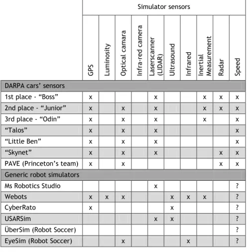
In Table 2.1, we compare the simulators, included those made by teams for use in the DARPA Urban Challenge 2007 [7][8][26][27][30][35][36][37][38][39][40][41][42].
While in table 2.2, these entries contain the information of which sensors their driverless cars had equipped during the competition. Detailed information about the different simulators that each team used is hard to find, and so, some of these features are marked as not determined. That’s specified in the table’s legend.
It's important to remember, at this point, that large scale traffic simulators are insufficient when it comes to simulation detail. They lacked in all the features mentioned in the previous section, except for that of "Large scale traffic" (and in some cases "3D visualization"), so they weren't included in the following table - Table 2.1. And since they don't simulate sensors at all, they weren't included in Table 2.2 either:
2 Left image source: Dr. Alexander Kleiner and Dr. Sven Behnke. Institut Für Informatik Freiburg (IIF),
Research Group on the Foundations of Artificial Intelligence, Software Laboratory. Accessed at:
http://www.informatik.uni-freiburg.de/~ki/teaching/ss05/sopra.html
Right image source: OxfordRescue Team 2008, RoboCup Rescue - Virtual Robots Competition. Accessed at: http://www.oxfordrescue.co.uk/
14 State of the Art
Table 2.1 – Summary chart with the features of today’s Robotic simulators
Simulator features 3D si m ula ti on 3D vi sua li za ti on La rge s ca le tra ff ic Mul ti A gent si m ul at io n V2 V / V2 I co m m uni ca ti on Col li si on det ect io n Sens or noi se Fa ilur e si m ula ti on Envi ro nment af fect ing s enso rs Envi ro nment af fect ing p hys ics Game engines Generic x x x x x x DARPA Teams’ simulators
1st place - ―Boss‖ x? x? x? 2nd place - ―Junior‖ x? x? x? 3rd place - ―Odin‖ x? x? x? ―Talos‖ x? x? x? ―Little Ben‖ x? x? x? ―Skynet‖ x?
PAVE (Princeton’s team) x? x? x? Generic robot simulators
Ms Robotics Studio x x x ? x Webots x x x ? x CyberRato x m x x
USARSim x x x
ÜberSim (Robot Soccer) x x EyeSim (Robot Soccer) x x x x
Table Legend:
x - Yes | m – Yes (considering modifications known to have been made already) x? – Could not be verified, and the information was not found, but assumed as being a positive
? – Couldn’t be determined | blank – No
The observation of this table reveals that most simulators nowadays lack important features for the simulation of autonomous vehicles.
Robotic simulators nowadays don’t seem to simulate:
Large scale traffic or pedestrians – We want to simulate how a driverless car responds to crowded areas, or traffic jams;
V2V/V2I Communications – We want to simulate how effective can these communications be between vehicles and the road network infrastructures and how they can improve operations;
Sensor Noise – There’s a wide amount of sensor errors due to their non-ideal nature. We need to simulate as much as possible when it comes to those errors if we want to know if the decision-making of the driverless car can take these into account and avoid malfunctions. These include sensor noise, illusions, reflections
2.3 – Types of Simulators 15
and echoes. For example light reflection with LADARs: Some surfaces do not reflect laser pulses well, where others reflect too well: Well painted road lines can be picked up with an LADAR system and reported as an obstacle, when in fact the vehicle can drive over them;
Failures – Sensors and actuators can simply malfunction and stop playing their role in real life situations. If we want fail-safe driverless cars, we need to simulate if they can minimize damage, safely come to a halt, or even drive and function close to normality even if some of the equipment is malfunctioning. This can range from simple GPS failure to a more serious failure involving steering or breaking;
Atmospheric condition, terrain condition, and environment - These are all real, and they affect sensors, actuators, and the behavior of cars as a whole. If these aren’t taken into consideration when simulating driverless cars, we can’t predict how well they’ll operate in the non-ideal real-life situations.
Some of the teams that participated in the DARPA Urban Challenge implemented their own simulators, while others used already existing simulators. Some of their own simulators had very practical features that are worth mentioning [26].
The simulator used by Princeton's team allowed the user to test their code in the simulator and then transfer it to the vehicle without the need to recompile [27], thanks to their use of the Microsoft Robotic Studio framework [43].
MIT’s simulator could play back data recorded in real life test runs, but the simulated obstacles reflected perfect data during those recorded runs, something that actual sensors didn’t obtain during the real life test runs.
CarOLO also used their simulator to test new software implementations before adding them to the vehicle, as well as confirming bugs found during real world tests. That’s something that the previous teams also did. But further development of this simulator has yielded a version in which multiple instances of their autonomous vehicle could be operated. In doing this, their software could learn efficient driving behavior in an environment in which multiple traffic vehicles exist. In addition, different versions of code could be run from the same starting point, running the same mission file, in order to compare their performance [35].
Tartan’s simulator also had the ability to add virtual obstacles to a real world environment during testing. In doing this, the vehicle was made to think there were obstacles in front of it even though there were none. This is achieved with Augmented Reality and Mixed Realities, when the real world reacts to interactions between the real world and virtual objects, and different realities interact continuously. These features are also available in the Intellwheels Simulator, and explained further here [44][45].
16 State of the Art
All these features are very time-saving when simulating and testing, and most of them were not easy to implement. They were developed for these simulators because time was the most important factor during the DARPA Urban Challenge, since the teams only had a few hours to update and validate their code between the events.
In the next table, we can compare which sensors are simulated by these generic robot simulators, and the sensors equipped in the DARPA’s driverless cars.
Table 2.2 – Summary chart with the sensors simulated by today’s Robotic simulators
Simulator sensors G PS Lumi nos it y O pt ica l ca m ara Inf ra -red ca m era La sers ca nner (LID A R ) U ltra so und Inf ra red Ine rti al Mea surem ent R ad ar Spe ed
DARPA cars’ sensors
1st place - ―Boss‖ x x x x x 2nd place - ―Junior‖ x x x x x x 3rd place - ―Odin‖ x x x x x ―Talos‖ x x x x ―Little Ben‖ x x x x ―Skynet‖ x x x x x PAVE (Princeton’s team) x x x x Generic robot simulators
Ms Robotics Studio x ? Webots x x x x x x ?
CyberRato x x ?
USARSim x x ?
ÜberSim (Robot Soccer) ? EyeSim (Robot Soccer) x x ?
Table Legend:
x - Yes | ? – Couldn’t be determined | blank – No
After a quick observation, you'll notice that car game engines aren't good enough because they're simply not sensor based, and they also lack some important simulation features like the ability to use Multi-Agents, V2V/V2I Communication, and sensor noise. They lack exactly what the real projects like DARPA Teams need to simulate how their cars will behave before testing in real situations.
2.4 – Limits and Specialization of the Simulators 17
2.4 – Limits and Specialization of the Simulators
Even after so much effort in the development of simulation, we are still far away from having an ideal simulator. The more features they tend to have, and the more realistic they are, the more resources they need to do their calculations in a reasonable amount of time. But simulation won't help much if it's oversimplified. In other words, we need a balance between the realism of the simulation, and the simplicity of its calculations. There are lots of things that we’d love to be able to simulate, but the sheer amount of processing power those would require are simply too much. Let’s talk about these limits.
Care must be taken with big quantities. When we're talking about large amounts of things in a simulation, they better be simple. You want to make some complex calculations, and many simple calculations. But you don't want to make many complex calculations. For such an example, let’s look at a large scale traffic simulator. The behavior of those thousands of vehicles is simplified to the point of the simulator being able to make thousands of calculations almost instantly. That’s because the decisions are simple, and their physics and movement are very simple as well.
But imagine if each one of these cars was aware of its environment through individual sensors, affected by generated noise. And all these cars would go through complex decision-making algorithms in order to send commands to their actuators, and then the simulation would have to calculate the next step based on what the actuators were ordered to do. If you multiply all these details by a thousand cars, it would take days to simulate a just a few seconds (if not less) of such a large scale scenario.
But it's very easy for a normal computer to simulate in real-time a few of these driverless cars. So the most obvious solution is to try and have more detail where it matters and less detail where it doesn't matter, depending on the specialization of the simulator. This means, in the case of this project, that we could try and have some detailed cars, with detailed decision-making and a more detailed physics simulation to study, and surround them with a crowd of less detailed objects, with their very own simple simulation.
3D simulation becomes a bit of a problem here, especially if you're adding a third dimension to the terrain. That’s because in this case, there's a whole lot more calculations involving those thousands of cars, to account for the extra dimension in their dynamic. For highway systems and most road networks, the changes in elevation are relatively small. So the simulated results are similar even without a 3D simulation. But with some cities and road networks, there are very drastic elevation changes. A 3D simulation is very important in these cases because it must be taken into account that sensors can't always look around corners, or down hills.
The vehicle performance is affected by the third dimension as well. It needs more power to climb uphill, and more importantly, it needs to break sooner and harder if it's going downhill. Weather conditions such as rain and snow also affect the way the vehicle performs.
18 State of the Art
Dirt, loose gravel, and other different ground surfaces can also be simulated to test the vehicle's control system. Again, a normal computer can simulate effects like these for a few cars, but not for thousands.
A good example of something that would be very hard to realistically implement in a simulation is GPS signal loss. The satellite signal can be occluded by pretty much anything that is big enough and in the way, like buildings, or trees. Realistic simulation of such a blockage would require simulation of the satellites and their orbits. The line of sight between the GPS receiver and the satellites would need to be tested to see if there was a signal loss or not. You can go as far as considering signal reflections off large buildings. But all these details would take a tremendous amount of processing power, and a lot of effort to implement. A balance between the effort and the results is essential: We can try and simulate GPS signal loss in various ways, from simple random time intervals, to specifying areas in the map where the GPS signal would be lost. As long as the result is that the GPS receiver loses the signal every once in a while, we get a simulator that can test the vehicle’s ability to predict its position roughly even if he temporarily loses the GPS signal.
There's also a good example of something that was very hard to simulate a few years back, and now, with some developments in computer technology, has became easy on processing needs. That's the example of vision based sensors. Vision algorithms used to be tested by simulating the markings in the roads, but the results would differ a lot to the real-life, where there are shadows from objects that might be out of the picture, atmospheric conditions like fog, storms, or even direct sunlight. Vision algorithms can now be tested more realistically because 3D rendering has evolved a lot lately. Now it's very common to have applications (any common video-game) that has a 3D engine implementing all these features, and can render them all in real-time with a reasonably cheap computer. It's a matter of streaming the result video output into a virtual camera instead of streaming it into a monitor screen. And you end up with a camera receiving a video that features photorealistic weather effects [32].
An ideal simulator would have to be indistinguishable from the real world. That might only be accomplished in an utopian future. But we can take what exists and adapt it to our necessities when it comes to simulation, by re-balancing the capabilities of the simulator.
2.4 – Limits and Specialization of the Simulators 19
Figure 2.14 - Screenshots of Crysis game3
3 Images source: TClms5400, ―PROJECT OFFSET vs CRYSIS vs ALAN WAKE‖, 4 Nov 2007. Accessed at:
20 State of the Art
2.5 – Summary
Although attempts to build driverless cars are not new, only recently has it become an intensive effort. Only now people are worrying with the effectiveness of the testing and simulating of their projects, and the simulators used are far from being ideal. The more features they tend to have, and the more realistic they are, the more resources they need to do their calculations in a reasonable amount of time. But simulation won't help much if it's oversimplified. And in some cases, it is.
We need a balance between the realism of the simulation, and the simplicity of its calculations. When deciding the type of simulation that we need to run, we need to decide what aspects are important to simulate, and what aspects really don’t matter much: We don’t have an ideal simulator, but the next best thing would be a simulator that allows us to choose what we want it to simulate.
Or, a connection between different types of simulators, that would each simulate different aspects and areas of a scenario to complement each other’s strengths. This is what this study aims for.
21
Chapter 3
Solution Design
In this chapter, the methodology of this study is discussed: The problem, the methods, and the tools. We’ll also describe the proposed architecture, its goals and functionalities, and at last, a brief analysis of which of those functionalities are implemented in the prototype.
3.1 – Methodology
In the following sections, the problem and the goal is described in detail, as well as the methods followed to reach the goals of this study. Also described are the tools and software used in the development, and the development environment itself.
3.1.1 – Problem Statement
The goal of this study is to achieve a simulator that, while being reasonably detailed with its physics calculations for the simulation of autonomous vehicles, can take into account influences from large amounts of entities, like the situation of driving in road network that is crowded with intense traffic.
The problem is, as concluded in the end of chapter 2, that a simulator that could both simulate huge amounts of traffic, while at the same time being very detailed with it all, would take a lot of computing resources to run in a reasonable machine. But a traffic simulator is not detailed enough to simulate autonomous vehicles, while a robotic simulator is not good enough influencing a detailed autonomous vehicle with the actions of thousands of other cars.
The goal is to overcome the limits of the two types of simulators by making them work together, cooperatively. The strengths of both types of the simulators are joined together to locally eliminate their flaws where we are analyzing the problem.
The traffic simulator achieves quantity, while the robotic simulator achieves detail. We don't need to know the details everywhere in a simulation, so we can have the simulators
22 Solution Design
cooperate in a way where the robotic simulator calculates the details where we need them, while being influenced by the larger, crowded, but simpler world outside that is being managed by the traffic simulator.
3.1.2 – Methods
First, the general characteristics of the concept project were sketched (Chapter 3.2). After that, a study of the state of art was done (Chapter 2), to confirm the strengths and weaknesses of the existing simulators and to further develop the concept project. The solution design was developed afterwards (Chapter 3), having confirmed what was needed to complement today’s traffic and robotic simulators. A proposed architecture for the solution design was defined, and then the programs and tools that would be used to build it were chosen (Chapter 3.1.3). Afterwards, further detailed goals and functionalities were defined for this project (Chapter 3.2.1), from which a few were selected to be implemented in a prototype simulator (Chapter 3.2.2). Finally, the prototype was achieved with modifications and implementations of the simulators previously chosen (Chapter 4), performance and functional tests were made, and the results noted down (Chapter 5).
3.1.3 – Techniques
The MAS-Ter Labs traffic simulator was chosen to perform the role of traffic simulator in the proposed architecture. It was practically chosen before even the study of the state of art of traffic simulation was done. There were a few reasons for this: It was developed in LIACC as well, so we were in close contact with those who had developed it. Also, its source was immediately available, unlike the commercial solutions already available. Although some of them have more analysis tools than this one, like graphics showing the traffic flow in different roads, waiting times, average speeds, etc, all this falls out of the scope of this dissertation. The role of the traffic simulator in this project is meant to influence the simulation of the autonomous vehicle being simulated in detail, in the robotic simulator.
Similar to the choice of the traffic simulator, the decision of the robotic simulator was rather quick too. The reasoning behind this decision is connected to the proven performance and flexibility of this simulator, as it has been used in different applications and adaptations. It has been successfully used for various competitions: Micro-Rato [10][46][47][48] (2001-2008), CiberMouse@RTSS [49] (2007-2008) and CiberMouse@DCOSS [50] (2008). It is open-sourced, so, the source code was readily available for us, and it was previously used at LIACC in several research projects such as a computational study on emotions and temperament in Multi-Agent Systems [51][52], development of cooperative rescue operations [53], and the already mentioned Intellwheels Project [54][55][56]. So, again, we are in close contact with those who had already worked with Cyber-Rato, and with those who had adapted it to various situations.
3.2 – Proposed Architecture 23
Next, the development environment was chosen: The software and libraries used to implement the prototype. All the simulators that were chosen for this project have been and are being developed under Microsoft Windows operating systems, so this simulator project should be developed under the same family of operating systems. This ensures better compatibility between interacting software and reduces the combined diversity of programming software requirements.
As for the programming software suite for the Intellwheels simulator, the choice was Microsoft Visual Studio C++. The Intellwheels simulator is in C++ language [31], and uses the Qt 2.3 libraries [57] from Qt Software (formerly known as Trolltech, before being bought by Nokia) [58], a set of libraries, with special classes and functions. These libraries are cross-platform (this means that they can be used in various operating systems, including Windows and Linux) and provide various class libraries that aid in the low level functions, allowing a higher level of programming. This version of Qt has direct integration with Microsoft Visual Studio C++, and this software provides a simple to use programming environment. This development environment was easy to set up too. Because of all this, that was the software we used to code and compile simulator-related code.
Regarding the simulation Viewer, and the simulation Agents: The ones modified were developed in Borland Delphi 7 [59]. It is an integrated software development environment that allows visual, event-oriented programming through Pascal programming language [60]. For the Viewer in particular, it calls and uses external OpenGL libraries [61][62] to render the 3D views. So a development environment using Borland Delphi 7 and OpenGL libraries was set up to code and compile changes to everything that was related to the simulator Viewer and the Agents.
Finally, regarding the MAS-Ter Labs traffic simulator, it was programmed in C++, and developed using the Eclipse software suite. This development environment was already installed and configured at the start of the project, so we saw no reason to change it: Since the workplace was already ready. It also used Qt Software’s Qt [58] libraries, but the version used here was more recent than the version used in Cyber-Rato. The Qt libraries were already integrated into Eclipse as well.
3.2 – Proposed Architecture
The architecture for this simulation software and its peripheral modules was sketched out while guessing a few desired characteristics, after considering what was thought to be the limits of today’s simulators. The initially desired goal was to create a detailed robotic simulator that could simulate autonomous vehicles as well as vehicles with semi-assisted driving technologies, among a realistic scenario of intense road traffic. This goal of ours was confirmed after a study of the State of Art was done in the fields of traffic and robotic
24 Solution Design
simulation which showed us that this subject still had a long way to go. So we developed the architecture further until it became a rich composition of connected modular software, as described below.
The figure below (Figure 3.1) is a simple schematic for the proposed architecture, where the different modules of the project are represented. The 2 greyed out ones in the centre of the figure are the modules which are the main focus and the point of start for the prototype: The Simulator, and the Simulation Viewer.
Figure 3.1 - Architecture of the simulator and its peripheral systems
The basics of the modules and their connections are as follows:
The Simulator connects to MAS-Ter Labs Traffic Simulator and to the Pedestrian Simulator [63] and receives traffic information from both the simulators mentioned above, adding that information to its calculations. It is also able to send information of its agents back to those simulators, so that they, in turn, can take that information into consideration when calculating the outcomes of their own simulations. By default, the map is loaded from the MAS-Ter Labs Traffic Simulator, and a parser reformats the map into the format needed to the Simulator calculations, as well as sending the map to the remaining peripheral simulators, like the Pedestrian Simulator;
The 3D Simulation Viewer connects to the simulator, and receives information from it to render the 3D representation of the simulation. It also has the functionality to send information of rendered images back to the Simulator for optical sensors like cameras (to test vision-based algorithms), including infrared cameras. Those rendered images, or video streams, are in turn sent to the relevant Agents so that they may analyze it. The 3D Viewer will also load the map from the Simulator for rendering purposes;
Simulator
Driver Agent Infrastructure Agent Driver Agent MAS-Ter Labs Traffic Simulator Pedestrian Simulator3D
Simulation
Viewer
3.2 – Proposed Architecture 25
Agents connect to the simulator and send all the information it takes for the simulation to know the necessary characteristics about the Agent. This includes component positioning and type of Agent. It can be a Driver Agent, in which case it will have a car assigned to it. It can also be an Infrastructure Agent, like traffic lights, intelligent street signs, communications access point, or obstacles.
3.2.1 – Modules’ Functionalities
Below, the specific objectives and functionalities of the different parts of this architecture are briefly described.
3.2.1.1 – External Simulators
MAS-Ter Labs Traffic Simulator can be defined as a multi-agent traffic simulator following a microscopic approach, and in this section, its solution design is described. This content is largely based in the third chapter of [2], which resulted in two papers that were accepted into two different conferences: Readers are referred to [4] and to [64].
Note that this is not the implementation of the MAS-Ter Labs Traffic Simulator prototype that was made, but the concept behind it. The development of the prototype of the MAS-Ter Labs Traffic Simulator is approached in section 4.1 of this document, just before the modifications made to the prototype.
The Simulation Engine is at first described in [2] as the MAS-Ter Lab framework Virtual Domain sub-system. Its high level architecture and all its main components are illustrated in Figure 3.2. Each of the represented components can be run in a different processing unit, and can be interpreted as independent applications.
26 Solution Design
Figure 3.2 - Simulation Engine High Level Architecture [2]
As shown in the diagram of Figure 3.2, the simulation engine is highly distributed and is formed of several independent applications, making it very flexible.
The Simulator Engine Controller (SEC) illustrated in the middle of the diagram is responsible for receiving all allowed actions provided by all its features and for executing them. It is also responsible for sending simulation state updates every time it is necessary.
The Moveable Agent (MA) components are agents that control network entities that are allowed to move (for instance a driver of a car, or a pedestrian). Basically, they receive information in regular time intervals about its surrounding and decide what actions they wish to perform upon the entities that they control. Each Moveable Agent controls one single network entities and the control actions he wishes to perform on the respective entity must be sent to the Mediator application that will be responsible for executing them.
The Graphical User Interface applications are responsible for receiving the simulated network state in regular time intervals and render it in a human readable graphical interface. The Semaphore Agent (SA) applications are basically agents that are responsible for controlling traffic light intersections with the objective of improving the overall traffic flow. Each Semaphore Agent only controls and regulates one single intersection. Their decisions are not solely based on the information they retrieve from their controlled intersection but also are based on information sent by other agents as well as negotiations between them. Instead of having as their only objective the improvement of the traffic flow of the downstream of a
3.2 – Proposed Architecture 27
traffic light intersection the Semaphore Agents also try to improve the overall traffic flow of the network by negotiating between each other before making decisions. These agents also provide, in regular time intervals, information about their decisions and intersection traffic flow state to the Semaphore Graphical User Interface Applications (Semaphore GUI’s) that represent this information in a human readable graphical interface.
The Mediator application is responsible for coordinating a certain number of Moveable Agents that control a physical entity in the simulation. This coordination includes translating the received world state information sent by the Simulator Engine Controller in regular time intervals into the surrounding environment perceptions (objects that surround and influence the behaviors of the simulator entities co-habiting in a common environment) of each agent it coordinates. It also includes receiving agents’ actions, aggregating them, calculating and updating the entities affected by those actions and sending the updated information back to the Simulator Engine Controller. The Mediator application is also responsible for launching new agents in the network entry points that populate its control area, as well as to kill agents that reach any of the network exit points (also inside its control area).
To achieve a desired perception of a part of the environment, an agent becomes a listener of all perceptible properties of entities that are inside an attention range (let us name it the agent’s foci) that the agent sends to the mediator. All objects within the range of the listener foci become its casters. This means that the mediator must create a perception message describing all the features of those objects, in other words it must translate the main information that defines all the objects that are considered to be casters of the listener agent into agent understandable information.
After the Mediator sent all the required perceptions to all agents within its controlled zone, it sends updated information on entities affected by the agent’s actions to Simulator Engine Controller. Finally, the Simulator Engine Controller can update all the changes that were provoked by the agents’ actions into its own network representation.
The example network illustrated in Figure 3.3 describes the concept of the agent foci in a typical simulation time step.
28 Solution Design
Figure 3.3 - Network Scenario exemplifying driver agents foci [2]
Imagine that in this example several time steps have already passed. So let us focus our attention on the driver of vehicle A. Based on the perception of the previous time step received, the driver decided to focus his attention on the front of his vehicle as illustrated by the gray sector of the figure. Now, assume that its desired action is to maintain its current velocity. The driver will send the mediator a message informing that it desires to maintain its velocity by inducing in its vehicle the necessary acceleration (assuming that friction exists) and that it desires to receive perceptions information about all objects inside its line of sight (foci).
In the described case, the only object that will be affected by the driver of vehicle A action is its own vehicle. The mediator then updates, in its control zone data structure, vehicle A’s position based on the acceleration provided by its driver. After finishing updating vehicle A’s position, it will search for all the objects within the received line of sight (foci) sent by the driver. Looking at the example scenario it is possible to identify four objects inside the agent foci:
The "Go ahead" arrow sign on its lane;
The "Turn left" arrow sign on its left lane;
The "Turn right" arrow sign on its right lane;
And a car at his front, on the same lane.
The characteristics that define these four objects are gathered by the mediator that translates them into a language that can be understood by the driver agent of vehicle A. Notice that the car in its front has the breaking lights on. Finally the mediator will send the constructed perception back to the driver of vehicle A.
3.2 – Proposed Architecture 29
The described sequence of actions that happened between vehicle A’s driver and the mediator will happen with all other drivers. While another simulation time step is not started the driver of vehicle A will reason on received perception to decide its next action. Since it received the information that the front vehicle is reducing its velocity it will probably decide also to reduce its velocity. Whatever its decision, the action will only be executed in the next simulation time step.
This ends the explanation of how the MAS-Ter Labs Traffic Simulator runs the simulation and a suggestion to how the many agents in it take decisions. The suggested architecture is composed of several different types of applications that can be distributed across several processing units. This kind of modularity enables this sub-system with the capacity of being an extendable and scalable solution. It is also believed to be the best solution to guarantee a good system performance when simulating large networks highly populated.
The developed prototype described in section 4.1, in the next chapter, only contains a few of the described features. Nevertheless, the prototype presents itself as the first stage of the development of the conceptualized sub-system where some of the nuclear concepts introduced in this chapter were implemented.
So, to conclude, some details on how this simulator connects to our solution design is briefly explained now. The Simulator connects to MAS-Ter Labs Traffic Simulator and receives traffic information from it. Specifically, the positions and other characteristics of the Agents (Moveable Agents, Semaphore Agents, etc.) are sent to the Simulator. The Simulator will send back to the MAS-Ter Labs Traffic Simulator the information about the agents connected directly to it. And both the simulators include that information in their calculations. This way, the agents in both simulators will perceive the agents from the other simulator, and react accordingly.
So that we can run a very big and complex scenario with this solution design, we have to make sure that the Simulator won’t get unnecessary information sent to it. The MAS-Ter Labs Traffic Simulator is very scalable, and so, can deal with the traffic simulation of a road network as big as the world’s biggest metropolises [2]. So, a module should be created in between the simulators, that keeps information about the Agents connected to the Simulator, and that filters the information from the MAS-Ter Labs Traffic Simulator, only letting information pass to the Simulator if it’s about Agents that are somehow in the range of the Agents connected to the Simulator.
In short, this connection will make the numerous traffic cars react to the autonomous cars that are being simulated in detail, without the need for many complex calculations involving sensors. In turn, the autonomous cars being simulated in detail will have their sensors detect the numerous traffic cars and react accordingly. Thus we achieve our main goal of being able
![Figure 2.1 - Driverless car named "Junior" of Stanford University Racing Team [7]](https://thumb-eu.123doks.com/thumbv2/123dok_br/19175064.942806/24.892.114.741.219.424/figure-driverless-named-junior-stanford-university-racing-team.webp)
![Figure 2.4 - U.S. Highway 280 study corridor at CORSIM Software [11]](https://thumb-eu.123doks.com/thumbv2/123dok_br/19175064.942806/26.892.112.745.271.492/figure-u-s-highway-study-corridor-corsim-software.webp)
![Figure 2.7 - Sensors Simulation at the Simulator of Victor Tango Team from Virginia Tech [8]](https://thumb-eu.123doks.com/thumbv2/123dok_br/19175064.942806/27.892.155.782.584.813/figure-sensors-simulation-simulator-victor-tango-team-virginia.webp)
![Figure 2.12 - Stanford’s simulator replaying data from the Urban Challenge final event [26]](https://thumb-eu.123doks.com/thumbv2/123dok_br/19175064.942806/30.892.122.751.748.952/figure-stanford-simulator-replaying-urban-challenge-final-event.webp)