Janeiro de 2013
Tese de Doutoramento
Ciência e Engenharia de Polímeros e Compósitos
Trabalho efectuado sob a orientação de
António Sérgio Pouzada
António Sousa Miranda
Carlos Alexandre Bento Capela
Mário Simões Correia
Modelling the ejection friction
in injection moulding
Estudo do atrito associado à extração
de peças moldadas por injeção
Guimarães, ___/___/______
Correia, M. S. Modelling the ejection friction in injection moulding
ACKNOWLEDGEMENTS
This work would have not been possible without the valuable support and help provided by several individuals, institutions and companies. I want to express my gratitude to all of them and refer those whose contributions were of major importance.
First and foremost I would like to thank my supervisor, Professor Pouzada, for the continuous support, availability and encouragement, for his valuable suggestions during all this work. His rigorous work methodology and outmost scientific skills were of great help regarding the scope, organization and the reviewing of all the work involved in this thesis. I can never truly value all the experience and teachings that he provided me during all the time I spent with him. Thank you very much Professor Pouzada!
To Professor Sousa Miranda, co-supervisor of this work, for the theoretical discussions, result analysis and reviewing of this document.
To my colleague of Polytechnic Institute of Leiria and co-supervisor of this work Doctor Carlos Capela for his support, encouragement and friendship. To the Polytechnic Institute of Leiria for the financial support and leave of lecturing during part of the research period.
I thank the Foundation for Science and Technology, for the research grant SFRH/PROTEC/49301/2008.
To Professor Walter Friesenbichler, from Montanuniversitaet Leoben, Department Polymer Engineering and Science, in Austria, for his interested support, and allowance to use their laboratory space and equipment during the period spent at the Polymer Competence Center Leoben.
I thank Doctor Gerald Berger for his support in the work developed in the Polymer Competence Center Leoben, for many interesting discussions on the demoulding issues and about the characterization of surface roughness.
To CEMUC, Center of Mechanical Engineering of the University of Coimbra, for providing the in-house finite element code DD3IMP.
To Damásio S.A. in Leiria, Portugal in the person of Eng. Hugo Damásio for the possibility of machining the metallic probes.
To Mr. João Ramos from F. Ramada, Aços e Indústrias, for the help on choosing the steels for the metal probes.
To my good friend Marta Oliveira from the Mechanical Engineering Department of University of Coimbra, for her support and friendship, and scientific skill sharing.
To my friend Rui Ruben for his friendship, good mood and help in the development of the computer program for roughness characterization.
To all my colleagues at the Polytechnic Institute of Leiria, especially the colleagues from my Mechanical Engineering Department.
To my PhD colleagues, Pedro Martinho, Joel Vasco, António Selada and João Matias for their fellowship, discussion of ideas and suggestions throughout this period.
To my colleagues of DEM-ESTG/IPLeiria and DEP/UMinho Guimarães, for their direct or indirect contribution to this work, and their continuous help and friendship. Special thanks to Carlos Mota and Carlos Dias of DEM-ESTG/IPLeiria for their help in the laboratory works.
To all my good and trustful friends, who have always supported me and encouraged me to proceed!
To my family (my parents and in-laws) for the magnificent support and encouragement. Without them it wouldn’t have been possible to achieve the
Correia, M. S. Modelling the ejection friction in injection moulding
objective that I had proposed. These words are for them even if they are written in English. Obrigado!
To my sons Maria Sofia and Nuno Luís for the smiles they gave me every morning. For all the days that I have stolen to them to ensure they will have a better future. O pai ama-vos muito!
Finally, but not for last... I wish to thank my wife. This research work and the degree achievement itself are entirely dedicated to her. Thank you for supporting me even when I was in a bad mood. I love you Fátima.
Correia, M. S. Modelling the ejection friction in injection moulding
ABSTRACT
The quality of parts produced by injection moulding may be affected during the ejection stage of the moulding cycle. At this stage the parts are mechanically forced to separate from the moulding surfaces. The ejection force depends on the shrinkage of the polymer onto the core and on the friction properties of the contacting surfaces at the moment of extraction. As during moulding there is a replication of the part on the mould surface the ejection process is also dependent on the plastic deformation of the moulded material. Ejection takes place in a very short time, hence the static coefficient of friction must be considered for modelling the ejection process.
To understand the contribution of the mechanisms involved in friction during the ejection stage, a mixed approach was developed: analytical simulation for the ploughing component, numerical simulation for the deformation mechanism, and an experimental inference for the adhesion. The study was based on the observation of three materials that are commonly used in injection mouldings: polypropylene, polycarbonate and a blend of polycarbonate/acrylo-nitrile-butadiene. The friction behaviour was studied with two testing methods: a prototype tester that is fitted to a universal testing machine, and an instrumented mould for the characterization of the friction force.
The relevance of roughness, temperature and contact pressure on friction was evidenced, on the actual value of the static coefficient of friction that applies in the demoulding of thermoplastic mouldings.
Correia, M. S. Modelling the ejection friction in injection moulding
RESUMO
A qualidade das peças produzidas por moldação por injeção pode ser afetada durante a fase de extração do ciclo de moldação. Nesta fase, as peças são forçadas mecanicamente a separar-se das superfícies do molde. A força de extração depende da contração do polímero e das propriedades de atrito das superfícies em contacto no momento da extração. No processo de injeção uma réplica da peça é gerada sobre a superfície do molde assim, a força de extração é dependente da deformação plástica do material injetado. A extração ocorre num espaço de tempo muito curto, por isso o coeficiente de atrito estático deve ser considerado para a modelação do processo de extração.
Para compreender a contribuição dos mecanismos envolvidos no atrito durante a fase de extração, uma abordagem mista foi desenvolvida: simulação analítica para a componente de sulcagem, simulação numérica do mecanismo de deformação e inferência experimental da componente da adesão. O estudo foi baseado na observação de três materiais de uso corrente em peças injetadas: polipropileno, policarbonato e uma mistura de PC/acrilo-nitrilo-butadieno. O comportamento em atrito foi estudado recorrendo a dois métodos diferentes de ensaio: um protótipo que está acoplado a uma máquina de ensaio universal e um molde instrumentado para a caracterização da força de atrito.
A relevância da temperatura, rugosidade e pressão de contacto no atrito foi evidenciada para os valores reais do coeficiente de atrito estático que ocorre na desmoldagem de componentes termoplásticos.
Correia, M. S. Modelling the ejection friction in injection moulding
TABLE OF CONTENTS
ACKNOWLEDGEMENTS ... iii
ABSTRACT ... vii
RESUMO ... ix
TABLE OF CONTENTS ... xi
1. INTRODUCTION ... 1
2. STATE OF THE ART ... 5
2.1 Injection Moulding ... 5
2.2 Shrinkage ... 6
2.3 Replication ... 8
2.4 Ejection in injection moulding ... 9
2.4.1 Materials ... 12
2.4.2 Friction in injection moulding ... 13
2.4.3 How to modify the friction properties ... 17
2.4.4 Optimization solutions to decrease ejection friction ... 19
2.5 The mechanism of friction ... 22
2.5.1 Ploughing ... 23
2.6 Theories and friction models ... 31
2.7 Methods of characterising friction properties ... 41
2.8 Objective of the work... 44
3. A MODEL FOR FRICTION IN INJECTION MOULDING ... 45
3.1 Model for the demoulding process ... 45
3.2 Surface texture ... 50
3.3 Roughness parameters ... 54
3.4 Friction based on geometrical aspects ... 57
3.5 Numerical model ... 61
3.6 Mixed-approach model for the assessment of the demoulding force components ... 64 3.7 Final remarks ... 65 4. EXPERIMENTAL WORK ... 67 4.1 Materials ... 67 4.1.1 Mould materials ... 67 4.1.2 Polymers ... 68 4.2 Processing ... 69 4.2.1 Injection moulds ... 69 4.2.2 Injection moulding ... 69 4.3 Characterisation tests ... 70 4.3.1 Mechanical testing ... 70
4.3.2 Topography characterization – Roughness... 70
Correia, M. S. Modelling the ejection friction in injection moulding
4.4 Friction testing ... 72
4.4.1 Friction testing - Mouldfriction ... 72
4.4.2 PCCL instrumented mould ... 75
4.5 Simulation ... 77
5. RESULTS AND DISCUSSION ... 83
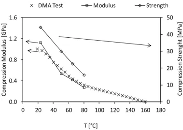
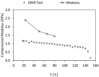
5.1 Materials characterization ... 83
5.1.1 Mechanical properties ... 83
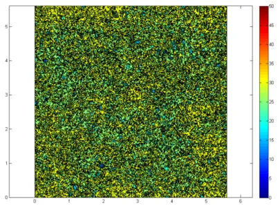
5.1.2 Roughness ... 87
5.2 Measurement of the friction force ... 89
5.2.1 Mouldfriction test ... 89
5.2.2 PCCL instrumented mould ... 108
5.3 Calculating the coefficient of friction ... 113
5.4 Analysis of the friction process ... 117
5.5 Application of the prediction model to PP ... 122
5.5.1 Input data ... 122
5.5.2 Numerical simulation of ploughing and deformation ... 123
5.5.3 Analytical prediction of ploughing ... 126
5.5.4 The adhesion component ... 127
5.6 Can friction in demoulding be predicted? ... 128
CONCLUSIONS ... 133
RECCOMENDATIONS FOR FURTHER WORK ... 137
REFERENCES ... 139
APPENDIX 1 – MATERIALS ... 151 APPENDIX 2 – PUBLICATIONS ... 159
Correia, M.S. Modelling the ejection friction in injection moulding
1. INTRODUCTION
Today thermoplastics are the most widely used materials for applications ranging from non-critical packaging products to very demanding technical parts. These parts are frequently made by injection moulding. In the injection moulding cycle, the mechanical process of ejection of the parts may affect their quality; at this stage the parts are mechanically forced to separate from the moulds. This ejection force may be quite high if the parts are moulded over deep cores.
The design of the ejection system depends on factors such as the draft angles, the surface finish, and the properties of the moulding material at the ejection temperature (Pouzada, Ferreira et al. 2006). The geometry and the location of the ejector pins depend significantly on the shape of the part and the architecture of the cooling system. Nevertheless, the most important factor for designing the ejection system is the ejection force that varies with materials and the processing conditions (Pontes, Pantani et al. 2002). The ejection system must not fail during production, since this will lead to the interruption of the production run or the damage of the mould (Araújo and Pouzada 2002). The friction force that develops between the polymer moulding surface and the mould surface of the mould results from the polymer shrinkage part onto the mould. Furthermore the polymer surface tends to replicate the mould surface texture, this may become an additional problem in the ejection stage. The more intimate contact caused by the shrinkage and the replication, in the case of
chemical affinity between the moulding and mould materials, may originate adhesion that has to be overcome upon ejection.
The optimisation of the injection mould systems requires that the frictional behaviour of the mouldings during ejection is known and predictable (Araújo and Pouzada 2002; Pontes, Pantani et al. 2002; Pouzada, Ferreira et al. 2006). The quality of parts produced by injection moulding may be affected during the ejection stage of the moulding cycle. At this stage the parts are mechanically forced to separate from the moulding surfaces. The ejection force depends on the friction properties of the contacting surfaces at the moment of extraction. As during moulding there is a replication of the part over the mould surface, the ejection process is also dependent on the yield strength and the plastic deformation of the moulded material. The duration of the extraction process is very short in time, thus the friction coefficient relevant for modelling the process is the static coefficient of friction (Pouzada, Ferreira et al. 2006).
The concerns of this study are in modelling the friction during the ejection stage. Basically the phenomenon that occurs here is the interaction between two surfaces, the moulding surface and the new plastic surface formed. To make the ejection of the plastics part, it is necessary to push it out from the mould cavity. It is necessary to wait that plastics part reaches a defined temperature. The choice of that temperature (ejection temperature) is very important. That is the difference from getting a good plastics part or a deformed or even destroyed plastics part. As ejection occurs while the mouldings are at elevated temperature, excessive or unbalanced demoulding forces may cause localized and gross deformation of the part, leading to part inefficiency (Pouzada, Ferreira et al. 2006). Thus, to eject the plastics part from the mould it is fundamental to know how the behaviour of this tribological system will be. The composition of this tribological system is: mould material, moulding material and the surfaces. During the injection processes, the temperature variations do not influence the behaviour of the mould (in most
Correia, M.S. Modelling the ejection friction in injection moulding
cases it is a metallic mould), but in the plastics moulding many changes occur during the injection moulding process. The polymer in the moulding, starts by being solid, then melts and finally cools down to the solid state again. So for the plastics part there is a complete thermomechanical cycle that causes big differences in the mechanical properties during the injection moulding cycle. The contact pressure, roughness and mechanical properties of contacting materials pair have a relevance action in the coefficient of friction.
The structure of this thesis is as follows: firstly, there is this introductory chapter, where it is explained the motivation to study this problem and what are the most important involved variables. This is followed by the review of the state of the art, Chapter 2, of the injection moulding process and ejection issues. At this stage some considerations are made about friction, friction models and roughness characterization.
In Chapter 3 the proposed model based on material properties and roughness is described. This model is a three-term model, including the various components of friction: ploughing, deformation and adhesion.
The fourth chapter describes the experimental methods. These include the materials, samples used in the friction tests and the equipment used to do the characterization of the mechanical properties. The samples used in the Mouldfriction prototype apparatus were made by injection moulding at the University of Minho. At the Montanuniversitaet Leoben it was used their instrumented injection mould. Also in this chapter is described the equipments used for the topography characterization. The chapter closes with the description of the simulation software used.
In Chapter 5 it is made the presentation and discussion of results. Tests were carried out to obtain the mechanical properties of the plastics material at various ejection temperatures, and the friction force evolution. It was possible
to compare the variation of friction force with the contact pressure, temperature and roughness.
Finally, the main conclusions are drawn and recommendations for further work are proposed.
Correia, M.S. Modelling the ejection friction in injection moulding
2. STATE OF THE ART
2.1 Injection Moulding
Plastics are used in a wide range of applications in engineering products such as gears, cams and bearings in substitution of metallic parts have gained an increased importance (Zhang 1998). Many of these products are made by injection moulding of engineering thermoplastics. To obtain the best performance of these products, for instance longer life time and reduced energy consumption, both tribological properties and processing conditions must be tuned up (Apichartpattanasiri, Hay et al. 2001).
Injection moulding is the most used process due to its flexibility for replicating complex shapes at fast production rates. During this process, the polymer undergoes a complex thermomechanical history, which influences the mechanical properties and the final dimensions (with respect to the corresponding mould dimensions) of the part (Titomanlio and Jansen 1996; Viana, Cunha et al. 2001).
The process encompasses four stages: filling, packing, cooling and ejection. Ejection is critical when complex geometry parts are produced and distortion or denting may be caused by the ejectors (Araújo and Pouzada 2002).
The performance properties of the part depend on the manufacturing conditions. The close relationship between processing conditions and mechanical properties was observed in amorphous and semi-crystalline
polymers, as for example (Schmidt, Opfermann et al. 1981). In injection moulding the thermal and the mechanical phenomena are strongly coupled. This thermomechanical environment is characterized by high-temperature gradients and stress levels and their local variations in the space domain of the moulding (Viana, Billon et al. 2004).
2.2 Shrinkage
The shrinkage of the moulding is an aspect of utmost engineering importance as it influences not only the dimensional accuracy of the product but also the ejection process from the mould. In the case of semi-crystalline materials where the shrinkage is higher than in amorphous polymers the prediction of shrinkage justifies complex consideration of the processing conditions and the molecular structure of the material (Schmidt, Opfermann et al. 1981; Pontes, Oliveira et al. 2002).
The demoulding force can be worked out using a suitable coefficient of friction and the normal force. According to Burke and Malloy (Burke, Malloy et al. 1991) shrinkage is the result of two separate phenomena: thermal contraction and directional distortion. The thermal contraction is volumetric in nature and is due to the reduction of the mean inter-atomic distance as temperature changes. The directional distortion is a result of the orientation of the polymer molecules during flow and their subsequent relaxation back to a coiled state when the flow ends.
Shrinkage is material dependent and varies significantly from amorphous to semi-crystalline polymers it being greater for semi-crystalline than for amorphous polymers which have more gradual volume contraction (Schmidt, Opfermann et al. 1981). The cooling rate, the glass transition temperature (with the substantial change of the shrinkage coefficient), the use of additives in the material and the degree of crystallization are other parameters that affect the overall shrinkage (Delaney, Bissacco et al. 2012). The shrinkage is affected by
Correia, M.S. Modelling the ejection friction in injection moulding
the flow-induced residual stresses and orientation, the flow-induced crystallization and the heat transfer. These factors are influenced by processing parameters such as packing pressure, packing time, melt temperature, mould temperature, injection speed, and material properties as well as geometric constraints (Kwon, Isayev et al. 2006). The anisotropic shrinkage cannot be predicted based only on volume shrinkage. It is greatly influenced by ejection temperature, is material dependant, and is very different
in
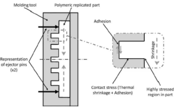
amorphous and semicrystalline polymers. Larger gates, long holding times, and high holding pressures in the injection moulding process can compensate for the shrinkage of the part (Pontes, Pantani et al. 2001; Pontes, Pantani et al. 2002; Kinsella 2004). In particular Pontes and co-workers focused on tubular mouldings where the shrinkage effects tend to be more evident. An early experimental study of shrinkage in injection moulded products was made by Jansen et al. (Jansen, Pantani et al. 1998). They found that if a constraint prevents the in-mould shrinkage to take place, the final shrinkage may decrease if the holding pressure and time are small.A numerical and experimental study for the determination of the ejection force using boxes of polycarbonate was carried out by Wang et al. (Wang, Kabanemi et al. 2000). This study concluded that during solidification the box conforms to the mould core geometry, while it deforms right after ejection. The core provides constraining forces to prevent free shrinkage and warpage of the box before it is ejected. During ejection, friction forces are induced at the mould-part interface, so the ejection force provided by the ejector pins is basically required to overcome friction and to remove the box (Figure 2.1). Therefore the analysis of the ejection process must be based on the constraining and friction forces resulting from mould-part interaction during solidification and ejection.
Figure 2.1: Mechanism of part ejection during injection moulding of plastics: (a) before ejection; (b) after ejection, (c) constraint by mould; (d) ejection (Wang, Kabanemi et al.
2000)
2.3 Replication
Injection moulding of plastics is basically a replication process. The main objective is obtaining a replica of the impression, the space that will be filled by the molten plastics. The critical steps in the replication processes are the filling, holding and demoulding of the moulded parts.
In injection moulding, during solidification, the plastics part shrinks onto the core while in the molten or very deformable state. As a consequence the moulding surface tends to replicate the topography of the moulding block core (Ferreira, Costa et al. 2004), Figure 2.2.
Correia, M.S. Modelling the ejection friction in injection moulding Figure 2.2: SEM images: 1- of the steel moulding surface, 2 – of polycarbonate sample
surface and 3 - polypropylene surface sample, (Ferreira, Costa et al. 2004)
The replication effect is not usually considered in tribological studies and processes but plays a fundamental role in the ejection process of injection mouldings (Pouzada, Ferreira et al. 2006).
2.4 Ejection in injection moulding
The demoulding step in the injection moulding process is the last of the moulding cycle. The demoulding stage is a critical issue recognized in injection moulding technology by many authors e.g.; (Heckele and Schomburg 2004; Derdouri, Ilinca et al. 2005), who highlight that most replication problems are not caused by the filling of the mould but by demoulding.
The location of the pin ejectors and the definition of its geometry depend significantly on the geometry of the part and the architecture of the cooling system. However, the most important for the dimensioning of the ejection system is the ejection force that varies with the materials and the processing conditions (Pontes, Pantani et al. 2002). Ejection is critical when complex geometry parts are produced and distortion or denting is caused by the ejectors (Araújo and Pouzada 2002), to avoid these problems Araújo et al. (Araújo, Pontes et al. 2003) recommended that efficient ejection systems should be designed for injection moulds. Hu and Massod (Hu and Masood 2002) developed an Intelligent Cavity Layout Design System (ICLDS) for multiple cavity injection moulds. From a practical point of view the system developed
can be used as a tool for designer to implement cavity layout design of injection mould at concept design stage. To prevent the part deformation or the damage of the moulding by the ejector pins, a method for the determination of the layout and size of the ejector pins was proposed by Kwak et al. (Kwak, Kim et al. 2003).
Pontes et al. (Pontes, Brito et al. 2004) performed a series of mouldings with polypropylene materials and showed that high viscosity grades lead to higher demoulding force. Usually the ejector pins cause a vestige in the part, but in some products this is not acceptable and the design of the ejection system must be considered with special attention (Pontes and Pouzada 2004).
Demoulding is particularly problematic for replication of microcomponents or components with microfeatures. Microparts are defined as those which have a mass in the range of a few milligrams, have features in the micrometre range or larger parts with dimensional tolerances in the micrometre range. Due to their small size such microparts and their replication tooling are physically weaker and thus both the tools and parts are more prone to physical damage. Breakage of a part within a mould can lead to additional problems since the residue may embed itself in subsequent parts, cause inadequate filling and potentially further damage to the replication tooling (Delaney, Bissacco et al. 2012).
In the case of micromoulds to complete the filling process the mould temperature is kept above the Tg of the polymer to ensure the flow of the melt into all impression features during the injection process. Upon complete filling, the mould temperature decreases rapidly to the ejection temperature of the part. This ensures the total replication of the part onto the mould surface (Attia and Alcock 2011).
In the case of the demoulding of microscale hot embossed pillar-type structures this is also complex because these structures have a reduced structural strength
Correia, M.S. Modelling the ejection friction in injection moulding
(Guo, Liu et al. 2007). In Figure 2.3 the main demoulding forces in pillar-type structures are highlighted.
Figure 2.3: Main demoulding forces in pillar-types structures (Delaney, Bissacco et al. 2012)
In other types of replication processes similar concerns have been raised regarding demoulding such as thermal imprint lithography (Song, You et al. 2008), hot embossing (Worgull, Kabanemi et al. 2007) and the automation of the powder injection moulding process (Fleischer and Dieckmann 2006). Even in these cases of replication processes it is suggested that there is an interlocking between the mould tool and the moulding part surfaces. To do the demoulding the degree of replication should be known, the relative velocity of the surfaces and the overall pressure distribution.
The surface roughness is a characteristic of all engineering surfaces. From the machining process to generate the surface of the replication tools imperfections, such as burrs, will appear on the surface resulting on undesired material beyond the desired machined features (Ko and Dornfeld 1991). The existence of these imperfections on the surface results in an increase of the demoulding forces in the case of hot embossing (Schaller, Heckele et al. 1999). After the hot-embossing replication, when the part is pushed relative to the replication tool, either the tool or the replicated part must deform sufficiently to allow the demoulding to occur.
Zentay et al. modelled the demoulding force for polyurethane seat-like foams to design robot grippers for the automation of the process (Zentay, Zoller et al. 1999). If the parameters of the production are not set precisely the demoulding force can be much greater than calculated. This is because adhesion force acts between the mould and the foam (Zentay, Zoller et al. 1999).
2.4.1 Materials
The mechanical properties of the materials involved in the ejection of moulded polymers may vary substantially by some orders of magnitude. Typically moulding blocks are made from alloy steels with elastic modulus around 200 GPa, whereas the plastics mouldings are in the order of 1-2 GPa (Crawford 1998).
In specific cases of rapid tooling, which is a field that is gathering increasing interest non-metallic materials with modulus of around 10 GPa are typical (Kinsella 2004; Kinsella, Lilly et al. 2005; Gonçalves, Salmoria et al. 2007). The relationship between the draft angle and surface roughness were investigated for stereolithography moulds by Cedorge and Colton (Cedorge and Colton 2000). Experimental demoulding properties were presented by An and Chen (An and Chen 2005) by measuring demoulding force and surface roughness to evaluate tool life and failure mechanism in order to obtain a working range for the process parameters. Due to the good geometric precision Westphal et al. also used stereolithography in the manufacture of hybrid mould moulding blocks and studied the performance and friction properties of this combination of materials (Westphal, Pouzada et al. 2006).
Using the benefits of the rapid prototyping processes Majewski and Hopkinson (Majewski and Hopkinson 2003; Majewski and Hopkinson 2004) studied the effect of tool finishing on ejection forces using direct metal laser sintered tools. Martinho et al. used various rapid prototyping techniques to produce mould
Correia, M.S. Modelling the ejection friction in injection moulding
inserts (Martinho, Cardon et al. 2008). In their research the ejection aspects associated to hybrid injection moulds were assessed.
Also Pontes et al. analysed the performance, especially in ejection of this type of tools (Pontes, Queiros et al. 2010). Hybrid moulds with rapid prototyped moulding zones by stereolithography (Ribeiro Jr., Hopkinson et al. 2004), or by vacuum casting of steel fibre reinforced epoxy composites (Sabino-Netto, Salmoria et al. 2008) were used to study the friction behaviour during the demoulding process.
This wide variation of the data coupled with the replication that occurs in injection moulding may definitely determine the tribological mechanisms associated to the ejection process. Moulders and mouldmakers have to know the mechanisms existent in the several components of the mould tool. The understanding of the wear mechanisms that link them to the design features may avoid or reduce the wear and extend the mould life (Engelmann, Hayden et al. 2000). For the ejection system attention is paid to the wear between pins, sleeves and bores which they pass through, but not only these metallic interactions should be taken in account for the mould performance. The wear on the core mould must be reduced and for this the use of lubrication was an option, but now with the requirements of today standard of the ejection part the use of lubricants became inappropriate to reduce the ejection wear (Engelmann, Hayden et al. 2002).
Therefore it is important, when testing for friction, to know not only the mechanisms involved in the friction phenomenon and the average value of the friction force (or coefficient of friction), but also the time dependence and stability of the friction force over a range of contact conditions (Blau 2001).
2.4.2 Friction in injection moulding
Removing replicated parts from the mould is described as the demoulding stage. At this stage the replicated part is moved/removed from the mould. This
brings about a friction problem, and a particular and special contacting problem. Plastics parts are typically replicated above the glass transition temperature of their polymers. So, during the cooling stage of the replication process the part shrinks and is constrained by the mould cores. The mechanical properties of the polymeric part and the mould are quite different (by some orders of magnitude) (Crawford 1998) and for this the shrinkage coefficients of the polymeric part and the replication tool (mould) are different too (Pouzada, Ferreira et al. 2006; Delaney, Bissacco et al. 2012). This shrinkage causes stresses in the cross-section of the part and generates normal forces to the contacting surfaces that results in an additional problem for the demoulding. The force described results from the injection process itself and the cooling of the new polymeric part generated. After this injection process it is necessary to remove the part from the mould core and for this the tangential force required must overcome this effect (Pontes and Pouzada 2004).
Figure 2.4: Demoulding forces for a cylindrical component (Delaney, Bissacco et al. 2012)
If atmospheric pressure does not exist between the part and the core mould during the demoulding action, a suction force will resist to the demoulding phase, thus increase the overall demoulding force required, as shown in Figure 2.4 (Delaney, Bissacco et al. 2012)
Factors that influence ejection friction
Economics imposes that the moulded parts are ejected as soon as they are dimensionally stable, in order to shorten cycle times (Ferreira, Neves et al.
Correia, M.S. Modelling the ejection friction in injection moulding
2002). As ejection occurs while parts are at elevated temperatures, excessive or unbalanced demoulding forces may cause localized and gross deformation of the part, leading to part inefficiency (Bhagavatula, Michalski et al. 2004). The ejection system cannot fail during production, since this leads to the interruption of the injection process or to the damage of the mould (Araújo and Pouzada 2002).
Despite considerable knowledge regarding component and tool design, mould filling, tool fabrication and general processing requirements, part demoulding has often been neglected or given little importance on its effects on parts manufacturability (Delaney, Bissacco et al. 2012).
For an understanding the factors that influence the demoulding issues, and the mechanisms associated to the factors contributing to the demoulding force Delaney et al. made a review and classification of demoulding issues and proven solutions (Delaney, Bissacco et al. 2012). This work categorises the factors that influence demoulding force as being: the tool and part designs, normal force (the totality of shrinkage), relative tool/part material properties, surface topography, surfaces energies, electrostatic charge and the amount of moisture present. The factors discussed influence the demoulding force, and affect the coefficient of friction of the contacting pair. So the factors affecting this coefficient of friction must be targeted in any attempt to systematically reduce the overall demoulding force and the stress which will be acting on the components and replication tools. Menges et al. categorise these factors as being the result of the mould, moulding geometry, moulding material and processing conditions (Menges, Michaeli et al. 2001). Later on Pontes et al. studied the effect of holding pressure and the core surface temperature on the ejection force for various polymers (Pontes, Pouzada et al. 2005).
Despite considerable knowledge regarding component and tool design, tool filling, tool fabrication and general processing requirements, part demoulding
has often been neglected or given little importance on its effects on parts manufacturability (Delaney, Bissacco et al. 2012).
Consequences in product characteristics and performance
Demoulding is a common reason for process failure, often resulting in part or tool distortion and breakage, and also can affect the lifetime of the replication tool. These problems are concerned to the generation of new surfaces (parts) onto the replication surface (mould). The replication of small or micro-structured parts by injection moulding raises several challenges compared to macro-sized parts (Heckele and Schomburg 2004). The challenges for the structural strength of replication tools, specifically the microcores for high aspect ratio parts are already noted into the replication of microfeatures. When applying the ejection force by the ejection pins after the replication of the polymeric part onto this mould microfeatures, the development of tensile stress greater than the core tensile strength as show in (Hopkinson and Dickens 2000) albeit for the case of macroscopic parts produced using stereolithographic tooling. To successful demoulding without deformation or destruction of the parts with microstructures depends not only on the geometry and material used but also on the nature and position of the ejection force applied (Michaeli and Gartner 2006). The productivity in the injection moulding process requires the minimization of the cooling time at the cost of higher temperatures and poor mechanical properties of the moulded part (Ferreira, Neves et al. 2002). Internal stresses are caused by the thermomechanical process and with the demoulding force applied consequences will appear in the moulding part. The effect of the demoulding process results in some cases in the permanent deformation or distortion of the replicated part, regardless the demoulding force is applied to the parts that should be rigid enough to ensure no deformation in the part (Wang, Lee et al. 1996; Engelmann, Hayden et al. 2000; Ferreira, Neves et al. 2001). Unfortunately previous experiences from tool designers combined with the industrial experience of the mouldmakers
Correia, M.S. Modelling the ejection friction in injection moulding
involving good felling and trial-and-error became preponderant in the options for the mould design. Such ad-hoc approaches can result in sub-optimal tool designs and increase both the product development cycle duration and the overall cost (Delaney, Bissacco et al. 2012). The demoulding problem is even more evident for micromouldings or parts with microfeatures. The demoulding of parts possessing dimensions or tolerances in the micrometre range needs a particular care, according to the difficulty of ejection (Heckele and Schomburg 2004). This phenomenon is accentuated for parts processing with high aspect ratios (Michaeli, Rogalla et al. 2000). Demoulding surface agents can be used, but this solution should be avoided in the case of medical or microfluidic applications parts, due to the possible contamination of the parts (Becker and Gärtner 2008). According to Michaeli and Gartner the concentrated demoulding forces provided by the traditional ejector pins are not suitable, because of the deformations or failure of the microparts (Michaeli and Gartner 2006) . A problem subsists with the mark of the ejector on the part. Mechanical ejector pins could be then an alternative solution (Wu and Liang 2005). According to Michaeli et al. new concepts were recently proposed for the demoulding techniques base on vacuum solutions, mechanical retraction systems of cavity or ultrasonic vibrations (Michaeli, Rogalla et al. 2000) . In addition, the surface roughness of the mould plays an important role during this phase. A new method has been developed by Yang et al. and involves decreasing the frictional coefficient of friction on the mould wall (Yang, Zhao et al. 2005). The material shrinkage has a major influence on the demoulding accuracy of the microstructured part. A precise control of the shrinkage by controlling the different processing phases can be a better solution for improving the demoulding (Giboz, Copponnex et al. 2007).
2.4.3 How to modify the friction properties
An extensive review of the effect of coatings in the contact mechanisms and surface design for generic processes was made by Holmberg et al. (Holmberg,
Matthews et al. 1998). During sliding, physical and chemical changes occur in accordance with the physical and chemical laws. The effects of the relative movement of the surfaces are friction, wear, temperature, sound and dynamic behaviour.
In the specific case of injection moulds the use of CrN coatings resulted in the reduction of frictional forces during ejection stages of a POM test ring. In the case of coatings of TiN or MoS2 higher friction forces were developed with
wider standard deviations (Dearnley 1999).
Charmeau et al. studied coatings for thermoplastics injection moulds to increase the lifespan of the mould before maintenance and decrease of the ejection force (Charmeau, Chailly et al. 2008). Polished surface and coatings processes were analysed. The coatings processes were PVD (Phase Vapour Deposition) and PACVD (Plasma Assisted Chemical Vapour Deposition) allowing thin coating manufacturing. The coatings investigated were Chromium Nitrium (CrN), Titanium Nitrium (TiN), Diamond like Carbon (DLC), glassy deposit (SiOx) and Chromium. Two polymers were tested: a
semi-crystalline poly(butylene terephthalate) (PBT) and a blend of copolymers of styrene acrylonitrile and acrylonitrile butadiene styrene (SAN/ABS). The analyses of the coatings in the ejection stage proved that their impact was polymer dependent. The ejection forces tends to increase for SAN/ABS and decrease for PBT.
Griffiths et al. (Griffiths, Dimov et al. 2007) studied the factors affecting the flow behaviour and paid a special attention to the interaction between the melt flow and the tool surface roughness. In another work (Griffiths, Dimov et al. 2008) they used design of experiments to study the demoulding of a microfluidics part as a function of a tool surface treatment and process parameters. The demoulding force was reduced and part quality improved with the use of the DLC surface treatment. The absence of a unique parameter level to optimize demoulding behaviour for the surface treatment and polymers
Correia, M.S. Modelling the ejection friction in injection moulding
investigated was highlighted. Later they investigated the effect of two different surface treatments on the demoulding behaviour of parts with microfeatures (Griffiths, Dimov et al. 2010). In this research work on DLC the surface originated a reduced demoulding force for PC and ABS compared to the untreated surface.
Neto et al. presented experimental results using steel inserts with CVD diamond-coating over a CrN interlayer (Neto, Vaz et al. 2009) . To reduce the wall adhesion and simultaneously improve the mould heat extraction rates was their main objective. This preliminary work demonstrated the possibility of using CVD polycrystalline diamond to enhance plastic injection moulding and also highlights the importance of further studies to statistically evaluate the durability of the coating.
Also Cunha et al. showed that the surface treatment with titanium nitride (TiN) and chromium nitride (CrN) reduces the coefficient of friction (Cunha, Andritschky et al. 2002). The PVD nitride coatings have significantly better wear resistance than the substrate protected by traditional processes (heat treatment, nitriding the surface or hard chromium coating deposition).
Van Stappen et al. (Van Stappen, Vandierendonck et al. 2001) proposed to simulate the demoulding of the injection process in laboratory and correlated the results with surface energy measurements of the coated mould and of the plastics material. The main objective was helping in the decision of a proper coating for a certain kind of plastics. No correlation could be found between the demoulding behaviour of plastics vs. coated moulds and the measured surface energy values.
2.4.4 Optimization solutions to decrease ejection friction
On reviewing polymer-based microfabrication technologies Becker and Gartner identified some important features of replication tools (Becker and Gärtner 2008): (a) the geometrical replication depends upon the geometrical
accuracy of the master, (b) for successful demoulding no undercuts in the structure itself can be allowed, (c) the surface roughness of the master should be as low as possible for replicating structures and (d) a suitable interface chemistry between master and substrate has to be selected.
To ensure a good solution for the demoulding issues the principle that rules the better solutions assumes that the tool and the part designs can be optimized to maximise the likelihood of successfully demoulding. Well-known examples for injection moulded products are to add draft angles on all tool cores, to have a constant wall thickness throughout the part and to gate the part on the thickest region. The part deformation problems can be approached by increasing the structural rigidity of the part for successful demoulding in terms of design such as adding bosses/ribs where possible and the selection of optimum materials and processing parameters (Delaney, Bissacco et al. 2012).
Other less known solutions to part design which may be more applicable to micro-structured parts include sacrificial barriers. These are non-critical structures deliberately included in the part geometry to resist overall shrinkage in the vicinity of the microstructures. In the microhot-embossing context Worgull et al. used a frame to limit the in-process flow front (to reduce warpage and shrinkage) and create sacrificial features to take up the high contact stress during demoulding (Worgull, Heckele et al. 2005). A similar auxiliary structure as a thermal stress barrier in the form of an additional circular structure around the field of microstructure has been proposed by Guo et al. (Guo, Liu et al. 2007). The simulation results by finite element modelling predicted a significant reduction in the stress experienced by microstructures. One disadvantage of this approach is the additional space on the component to locate the sacrificial stress barrier.
Wang and co-workers studied an optimum ejector pins layout that distributed the overall ejection force among a series of ejector pins In these works different layouts, location, dimension, quantity and distribution of the ejector
Correia, M.S. Modelling the ejection friction in injection moulding
pins were considered. The objective was to identify the balanced layout causing minimum stress and deformation to the product and developed a strategy of numerical optimization of the demoulding stage. The studies dealt with conventional demoulding concept of ejector pins to physically push off the component from the mould core. To predict the distribution of the ejection force among ejector pins a finite element thermoviscoelastic solidification analysis was performed. An assumption of uniformly friction distribution cannot be generalized and the balanced ejection is not simply balancing the ejector pins layout according the interface areas. The primary premise, according to Wang et al. (Wang, Kabanemi et al. 2000), is that the corners of the moulding will limit the shrinkage and thus minimise the contribution of warping to demoulding force. On the other hand the local stiffness of the part must be considered, so in reality the local contact pressure will be influenced by both the shrinkage and stiffness of the part.
Bataineh and Klamecki (Bataineh and Klamecki 2005)studied improvements to the ejector pins layout to predict local mould-part force. Experiments were made using ring and box-shaped parts to provide input of the coefficient of friction, material properties and total and local ejection forces, to the simulation process. Michaeli and Gartner proposed and trialled non-destructive methods to do the demoulding without ejector pins or plates (Michaeli and Gartner 2006). The method used was demoulding with ultrasonics. It was expected that with the utilization of ultrasonics the oscillation between the mould and the part would reduce the wall adherence this resulting in the reduction of the demoulding force, but the experimental results did not report this assumption.
Despite the improvement of the ejection system, the surface topography has been used as an indicator of the most dominant friction mechanisms. The principle of solution is that the replication tool surface has a topography which will minimise the overall demoulding force. In the context of minimizing the
overall time required to finish rapid tools Majewski and Hopkinson summarized the effects of tool surface roughness on part quality and demoulding force for parts injection moulded using laser sintered tools (Majewski and Hopkinson 2003). In this work it is suggested that the ejection force can be minimised through the use of very low surface roughness. However, Ferreira et al. (Ferreira, Neves et al. 2001) mentioned that very good polished surfaces (mirror-like) may facilitate the formation of a seal which prevents air entering the gap between the core and the part resulting in the local formation of vacuum forces that can make difficult to separate the part from the core. Finishing the core in the ejection direction air can enter the gap allowing atmospheric pressure to exist between the plastic and the steel core, eliminating the vacuum force. The existence of an optimum core surface roughness was reported by Sasaki et al. (Sasaki, Koga et al. 2000) with similar results observed by Pontes et al. (Pontes, Ferreira et al. 2004) and noted by Pouzada et al. (Pouzada, Ferreira et al. 2006). As the previous authors Kyuichiro (Kyuichiro 1995) verified in several pin-on-disk tests the same behaviour.
2.5 The mechanism of friction
In the early work on the discussion of the mechanism of friction Bowden put a simple question “What is the cause of the resistance happening at the interface between solids during sliding?”(Bowden 1952). At that time Bowden hoped that the discussion not becoming a humdrum topic.
In their classic textbook Bowden and Tabor identify two main contributions to friction (Bowden and Tabor 1986): the first one is connected to the adhesion between the contacting asperities, and the second to the asperities or bulk surface plastic deformation.
It is desirable to be able to isolate the contribution of each friction mechanism to the overall demoulding force (Delaney, Kennedy et al. 2010). The main
Correia, M.S. Modelling the ejection friction in injection moulding
mechanisms in the normal sliding conditions encountered in engineering applications are the deformation and the adhesion components of the friction (Kim and Suh 1991). The deformation component of friction includes the ploughing of the surface by the hard surface (Kim and Suh 1993).
According to the adhesion and deformation model of friction (Bhushan 2002), the coefficient of friction can be presented as a sum of the adhesion component and the deformation component.
2.5.1 Ploughing
Kim and Suh (Kim and Suh 1991) described the mechanism of friction on three basic contributing factors. The frictional force is generated by asperity deformation, wear particles and adhesion. These developments suggested that the mechanical interactions at the sliding interface are the primary causes of friction between two surfaces.
Ploughing friction models assume that the dominant contribution to friction is the energy required to displace material ahead of a rigid protuberance moving along the surface. Such ploughing through plastic deformation will result in the formation of scratches across the surface of the replicated parts. But on the other hand the movement of the protuberance does not result in plastic deformation so there will be no scratching of the surface. This phenomenon, known as hysteresis, occurs due the subsequent recovery of the polymer after the indentation (Delaney, Bissacco et al. 2012). All the deformation that exists is elastic deformation and totally recovered. It is governed by the elastic or viscoelastic properties of the polymer, the relative velocity of the surfaces (the demoulding rate), and also the overall pressure distribution. Worgull et al. published results from simulated replication trials with the variation of the demoulding rates (Worgull, Kabanemi et al. 2008). The coefficient of static friction becomes substantially higher for the decrease of the demoulding rate.
The ploughing term associated to a conical asperity has been discussed by Tabor (Tabor 1981), who did not consider the mechanical properties of the contacting pair. In the Tabor model for sliding friction, the asperities (protuberances) of the harder surface are assumed to plough through the softer one. The ploughing resistance causes a force contributing to the frictional force. This contribution is referred to as the ploughing component of friction, the deformation term. A simple estimation for conical asperity of semi angle θ (Figure 2.5) gives the coefficient of friction due the ploughing term as:
θ π
μd = 2cot (2.1)
The slope of surface asperities is less than 10°, that is, the semi angle θ > 80°, and the coefficient µd should be about 0.05 and less. When elastic contact occurs, µd is often assumed to be negligibly small.
Figure 2.5: Ploughing term due to a conical asperity on a soft material (Tabor 1981)
During sliding the engineering surfaces (which are rough) are subjected to the so-called ploughing of the hard asperities into the softer mating surface. Hard particles, metal debris or other particles from the environment may also contribute to this deformation. With elastic deformation, that is if the penetration of asperities is small, the ploughing does not result in the formation of permanent tracks. If plastic deformation occurs, which is almost always the case with metals, grooves are left behind in the softer surface (Bowden and Leben 1939). Van Beek considers if the hardness of sliding surfaces differs by > 20% the roughness summits of the hard surface penetrate the softer material
Correia, M (van B code th To redu increas Beek 2 M.S. eek 2006). hat consider Fig uce friction ing the con 006). The Figure rs a rigid sph gure 2.6: Mod n due the pl ntacting rad M e 2.6 shows here in cont del of ploughin loughing lo dius and ori
Modelling the e s the model tact with a l ng friction (va ow roughne iginating a ejection friction l used in th less hard sur
an Beek 2006) ess should b larger area n in injection mo he finite ele rface. ) be achieved a of contact oulding ement d, this t (van
2.5.2 Adhesion
Before refer the phenomenon of adhesion we must refer first the adsorption. It is an essential fact that the surface can be treated both as an ideal geometrical object with a highly peculiar topography and a physical object possessing a certain thickness and a specific mechanical behaviour. The atoms and molecules belonging to the surface have fewer “neighbors” than those in the bulk (van Beek 2006). This simple fact has consequences for the geometry and physics of a surface, so the interactions between its atoms and their neighbours vary, distorting the force field that penetrates to the depth of several interatomic distances (transitional layer). An excess of energy appears and the surface tension is a measure of a surface energy. Solids can be rated in the order of their surface tension into three groups; solids with high surface tension up to several Joules per square meter in vacuum (most of the metals and their oxides); solids with medium surface tension of the order of tenth fractions of Joule per square meter (e.g., ionic compounds) and solids with low surface tensions (most of the polymers).
Figure 2.7 shows schematically that the structure of the boundary layer is quite intricate. The mechanical behaviour of boundary layers accordingly demonstrates a rich spectrum of properties ranging from viscoelastic behaviour to perfectly elastic one (Myshkin and Petrokovets 2004).
Correia, M.S. Modelling the ejection friction in injection moulding Figure 2.7: Surface layer structure: A – initial structure; B – region where supermolecular structure is fractured and oriented, as well as where the crystalline phase breaks down partly; C
– strongly dispersed layer; D – low-molecular layer; E – gaseous phase; W – working layer (Myshkin and Petrokovets 2004)
Therefore the solid surface with the region adjacent to the bulk can be schematically represented as a laminated system comprising boundary (adsorbed) and the solid (bulk) phase of the basic material. Such representation is frequently convenient to analyse and simulate the surface effects in friction and wear (Myshkin and Petrokovets 2004).
When two very smoothly-finished and cleaned surfaces are pressed together, they may stick together through atomic or intermolecular forces. At this time should be made a distinction between cohesive forces, which occur between identical mating materials, and adhesive forces, which occurs between dissimilar mating materials (van Beek 2006).
For similar mating materials cohesive forces are easy to illustrate with gauge blocks (Figure 2.8).
Figure 2.8: Atomic interaction at an interface as a cause of adhesion (van Beek 2006)
Gauge blocks are precisely manufactured blocks to calibrate micrometers and callipers. When the blocks are pressed together they remain attached. This phenomenon is explained by the very smooth super-finished surfaces that result in a large real contact area over which the atomic forces act.
For dissimilar mating materials the contact may create adhesive forces, this adhesive force is generally weaker than cohesive forces. Therefore the friction coefficient for two similar materials is normally higher than the friction coefficient for two dissimilar materials. As a general rule, contact between two similar materials must be avoided. This applies to metals, polymers and ceramic materials.
To help this explanation we must make a reference to materials compatibility. One factor determining the extent to which adhesive forces occur between different materials is their metallurgical compatibility (mutual solubility). The metallurgical compatibility is related to the surface energy of both materials γa
and γb and the interface energy γab in the contact between the materials. When
two materials a and b come into contact, adhesive energy of Гab= γa+ γb- γab is
released. When two equal and smoothly finished materials are pressed together the surface energy is completely determined by the adhesive energy, γab=0,
Гab=Гaa= 2γa. With two different materials (atom diameter, valency, packing,
orientation) some interface energy remains, reducing the adhesive energy that is released. For most material combinations the interface energy lies between
Correia, M.S. Modelling the ejection friction in injection moulding
γab=½(γa+ γb), defined as metallurgical incompatible (poor mutual solubility)
and γab=¼(γa+ γb), defined as metallurgical compatible (van Beek 2006).
In the particular case of friction during demoulding in the injection moulding process, the adhesion term which is a surface effect, is a very difficult mechanism to isolate from the others (Ebnesajjad 2006). Delaney et al. (Delaney, Bissacco et al. 2012) have identified in the review the adhesion friction mechanisms and have categorized as consisting of thermodynamic/chemical adhesion, electrical/electrostatic adhesion and capillary attraction, as shown in Figure 2.9.
Figure 2.9: Adhesion mechanisms (A) thermodynamic/chemical/kinetic, (B) electrostatic, (C) capillary attraction (Delaney, Bissacco et al. 2012)
Some materials by diffusion or interfusion of chains may merge if the molecules of both materials are mobile and soluble in each other. For the case of stereolithography moulds Gonçalves et al. (Gonçalves, Salmoria et al. 2007) observed that polymers showed adhesion characteristics. The chemical affinity between the two stereolithography resins used and the moulding materials were evidenced by the friction experiments. The coefficient of static friction between the stereolithography blocks and the mouldings results not only from the roughness replication, but also from the adhesion between the stereolithography block and the thermoplastic. The latter effect is more important in the cases where chemical bonding and diffusion of the molten thermoplastic into the stereolithography block occurs. The degree of diffusion depends on the chemical affinity (or miscibility) between the materials, which
can be estimated from the Hildebrand solubility parameter. This parameter establishes a relationship with the polarity of the molecules which can be related to the chemical affinity of the materials. Generally, polymers with the same solubility parameter, and consequently the same cohesive energy density, tend to be miscible with each other or to show adhesive characteristics (Petrie 2000).
The use of the Hildebrand solubility parameter tables help to choose the best resin for a stereolithography moulding block if the thermoplastics to be injected is known in advance. The adhesion between the stereolithography resin for the moulding block and the material to be moulded can be assessed by a friction test made with samples overmoulded in testing blocks sterolithographed in the material similar to that used in the injection mould. This test informs not only on the effective friction properties but also on the likelihood of chemical adhesion between the thermoplastics and the stereolithography resin (Gonçalves, Salmoria et al. 2007).
The electrostatic adhesion arises from charge generation during contact. Some conducting materials from electrons transference could form a difference in electrical charge at the joint creating electrostatic attractive force and this force will be resistant to the separation (Delaney, Bissacco et al. 2012).
In case of lower values of roughness the gap between the contacting asperities can become filled with moisture resulting in the development of a meniscus force (capillary attraction). Adsorption of moisture at the narrow gap can lead to the formation of a liquid bridge resulting in surface tension. To Yoshikazu et al. (Yoshikazu, Kenji et al. 2001) the meniscus force is a major cause of the increment of the ejection force for smoother core moulds surfaces. An apparatus was used by Delaney et al. (Delaney, Kennedy et al. 2011) to predict the work of the adhesion for the demoulding force optimisation. In this research the definition of contact angle and wettability were used. It was
Correia, M.S. Modelling the ejection friction in injection moulding
planned by the researchers that the model will be suitable for implementation in Finite Element Modelling.
Recently Chen and Hwang (Chen and Hwang 2013) developed an adhesion force tester to measure the adhesion force between the sample and tool surface during the injection moulding process.
2.6 Theories and friction models
Friction is a remarkable phenomenon. We have still much to learn about its nature. The history of friction is a very long story, dating back to the invention of the wheel, in order to reduce friction, and the discovery that one could produce fire from the heat generated by rubbing two sticks together, a positive use of high friction (Blau 1996). The contact between surfaces usually results in wear (Zambelli and Vincent 1998). Friction between contacting bodies is manifested in two ways. One way is as a force that must be overcome to initiate or sustains the motion. The other way is as the energy that is dissipated during relative motion. While friction and wear are distinct phenomena, they are also related. Wear mechanisms contribute to both aspects of friction, because wear processes require the application of force and energy consumption (Bayer 2002).
Figure 2.10 shows the transportation of an Egyptian colossus from a painting in the tomb of Tehuti-Hetep dated about 1800 BC. The colossus is fixed to a sledge and is pulled along by 172 men. One very interesting feature is the man on the front of the sledge who is apparently pouring a liquid on to the ground in front of the sledge, suggesting an early appreciation of the benefits of lubrication. It is estimated (Dowson 1998) that the colossus weighed approximately 60 tons (600 kN) and that, on average, each man could exert a pull of 800 N. For this in that epoch the people understood that could decrease the friction developed between the ground and the Egyptian colossus.
Figure 2.10: Transporting an Egyptian colossus (from D. Dowson, The History of Tribology, MEP, 2nd Edition, 1998, p.38)
Frictional behaviour has been the subject of systematic, documented studies and measurements for more than half a millennium Figure 2.11. One way to decrease this phenomenon is the use of lubrication, but this aspect will not be included in this discussion, because we are only interest in the direct contact between surfaces.
Figure 2.11: Timeline showing the correspondence between early work in friction research and the technology of the time (Blau 1996)
Friction is the resistance to motion during sliding or rolling that is experienced when the surfaces of two solid bodies move tangentially over another, Figure 2.12.
Correia, M Figure 2 and (b) The va friction motion relative . Th 2.13. Figure 2 force There a the inte 1. 2. 3. M.S. .12: Schemati ) a body rollin lue of the t n force, n is initiate e motion is e static fric 2.13: Tangenti required to in
are three law erface): The Frictio The Frictio (A) The Frictio ic illustrations ng on a horizon angential fo or . in the inte known as t ction force ial force as a f nitiate motion ws of dry fr on Force (F) on Force (F on Force (F) M s of (a) a body ntal surface; W force (Bhush orce that is it may tak erface. The the kinetic is higher t function of tim an is motion. (Bhu riction (dry ) is directly F) is indepe ) is indepen Modelling the e y sliding on a W is the norm han 2002) required to ke a few m tangential (or dynami than the ki me or displace the kinetic fri ushan 2002) meaning th proportiona endent of th ndent of the ejection friction surface with a mal load (force)
o initiate mo milliseconds force requ c) friction f inetic frictio ement; iction force re hat there is n al to the app he apparent Sliding Vel n in injection mo a free body dia ) and F the fri
otion is the s before re ired to mai force, on force, F is the static fr equired to sust no lubricati plied load (W t area of co locity (V) oulding agram, iction static lative intain or Figure riction tain ion of W) ontact
The first two laws arise from the studies of Leonardo da Vinci and Amontons, although the latter is actually credited with their formulation, as we know them today. These laws are widely applicable to the dry friction between interacting surfaces.
The first law gives rise to the definition of the coefficient of friction (µ) and the well-known equation
(2.2) for F and W see Figure 2.12).
The second law is interesting, being counterintuitive with friction apparently independent of the area of contact. That is until one notes that it is the apparent area of contact that is referred to, not the real area of contact. The surfaces contact only at the peaks of asperities, the real area of contact being only a very small proportion of the total area of interaction between two surfaces, the apparent area of contact.
Friction will undoubtedly depend upon the real area of contact but it is feasible that it will remain unchanged with variations in apparent area of contact over a wide range of operating conditions. For example, if the apparent area of contact was reduced for a given load, then the real area of contact as a proportion of the apparent area of contact would increase but it may remain constant in absolute terms, resulting in the same friction force.
The third law was introduced by Coulomb in the 18th century. It has a much smaller range of applicability that the first two and should therefore be treated with caution when considering real engineering systems.
Friction is affected by many factors: material, environmental, interface condition, operating conditions. Some of those factors are difficult to assess and control. That is why friction becomes so complex to simulate in laboratory tests or to reproduce by theoretical modelling.
Correia, M The fri in dry alone, b interfac forces bodies The qu and en theoret Suh et mechan The ov three co Starting et al. contrib compon friction change M.S. ction force or in wet l but a system cial mean. C acting, resp under relati Figure 2. uantity know gineering a ical studies al. (Suh, M nisms: aspe verall frictio omponents g with the s 2003) pre butions of tw nent. They n (static and es in roughn is the tange lubrication. mic reply a Conceptuall pectively, pa ive motion 14: From the wn as the co and it is an are based o Mosleh et a erity deform on coefficie (Equation ( suppositions sented a m wo compon conclude th d kinetic). T ness but didn
M
ential force Thus, frict as a function
ly, the fricti arallel and (Blau 2001) notes made by oefficient of empirical on this empi al. 1994) pr mation, adh ent was the (2.3) and Fi s of Suh et model for nents that w he roughnes The theoret n’t respond Modelling the e opposite to tion is not n of the sta ion force is perpendicu ) (see Figur y Leonardo D f friction ha law of Cou irical law. resented fric hesion and p en given by gure 2.15). al., Ferreira the coeffi was the plou
ss influence tical model to temperat ejection friction o the movem a property ate of the su s defined as lar to the in re 2.14). Da Vinci (1452 as long been ulomb fricti ction as com ploughing y the weigh a et al. (Fer cient of fr ughing and e directly th developed ture variatio n in injection mo ment, establ of the mat urface and o s the ratio o nterface bet 2-1519) n used in sc ion. Most o mposed of of the inter hed sum of (2 rreira, Laran friction that the deform he coefficien was sensib on. oulding lished terials of the of two tween cience of the three rface. these 2.3) njeira t has mation nts of ble to