JournalofMaterialsProcessingTechnology233(2016)89–99
ContentslistsavailableatScienceDirect
Journal
of
Materials
Processing
Technology
j ou rn a l h om ep a g e :w w w . e l s e v i e r . c o m / l o c a t e / j m a t p r o t e c
Computational
and
physical
simulation
of
fluid
flow
inside
a
beam
blank
continuous
casting
mold
Johne
Jesus
Mol
Peixoto
a,∗,
Weslei
Viana
Gabriel
a,
Leticia
Queiroz
Ribeiro
a,
Carlos
Antônio
da
Silva
a,
Itavahn
Alves
da
Silva
a,
Varadarajan
Seshadri
baDepartmentofMetallurgicalEngineering/REDEMAT,FederalUniversityofOuroPreto,OuroPreto,Brazil bDepartmentofMetallurgicalEngineering,FederalUniversityofMinasGerais,BeloHorizonte,Brazil
a
r
t
i
c
l
e
i
n
f
o
Articlehistory:
Received16October2015
Receivedinrevisedform7January2016 Accepted12February2016
Availableonline17February2016
Keywords: Beamblank Fluidflow Continuouscasting Nearnetshapes PIV
a
b
s
t
r
a
c
t
Themainfeaturesoftheflowfieldinsideabeamblankcontinuouscastingmoldhavebeenassessed throughmathematicalandphysicalmodelingtechniques.Experimentaltechniquessuchasparticle dis-persionthroughadditionofdyeandparticleimagevelocimetryhavebeenusedinaphysicalmodelofthe moldtoassesstheflowpattern.Differentcombinationsofnozzlegeometryandthroughputhavebeen employedandtheexperimentalresultshavebeenanalyzed.Inthecaseoftwotubularnozzles,which shouldensuregoodthermalandflowsymmetry,sixvorticeswereobservedinthemold,twonearthe webandtwoineachoftheflanges.Increasingtheflowrateofthefluidfrom100L/minto150L/min leadstoachangefrom0.74mto0.84minthejetpenetrationdepth.Howeverevena67%increaseof thenozzlecrosssectiondidnotaffectthisparametersignificantly.Experimentswithonesingletubular nozzle(53.2mminsidediameter)werealsocarriedoutandtheresultingflowasymmetryhasbeen char-acterized.Thedifferenceinthefluidvelocitiesatthefiletscouldleadtounequalsolidshellgrowth.The depthofjetpenetrationislargerthanmoldnominallength(0.8m).Fluidflowstructureasdetermined byPIVmeasurementsandCFDsimulationsshowagoodagreement.
©2016ElsevierB.V.Allrightsreserved.
1. Introduction
Actualexperimentaltrialstodetermineoptimumconditionsof operationinthecontinuouscastingunitcanleadtointerruptions intheproduction scheduleandconsequentlylossof productiv-ityandprofitability.Mathematicalanalysisandphysicalmodeling experimentsinthelaboratoryareanalternativetoachieve opti-mumconditionsforachievingincreasedproductivityandimproved qualityoftheproduct.Hibbeleretal.(2009)developeda math-ematical model for simulating thetemperature profileand the stress/deformationfieldinsidethesolidifyingshellinabeamblank continuouscastingmold.Thismodelisalsocapableofthrowing lightonthemechanismofcrackformationatthefiletregion,dueto acombinationofathinnershell,mechanicalstressandanextended airgap.
Leeetal.(2000)hadobservedthattheairgapwasmainlyformed intheflange-tip,whichretardstheshelldevelopmentinthisregion. Theirregularadvanceofthesolidifyingshelliscausedby
nonuni-∗Correspondingauthor.
E-mailaddress:johnepeix@yahoo.com.br(J.J.M.Peixoto).
formheattransferandthestressconcentrationinthethinnestpart ofthesolidifiedshell,implyingahigherprobabilityofoccurrenceof cracks.Zhaoetal.(2014)detectedthatalargetemperature differ-encebetweenthefiletandotherregionsonthesurfacecancause longitudinalcracksatthefillet,andanoptimizationinthecooling systemcanimprovethequalityofthebeamblank.
Theflowfieldinsidethemoldisknowntoimpactthesteel inter-nalcleanlinessandthegrowthoftheshell.Intheconventional continuouscasting,theflowfieldisinfluencedbymoldgeometry, castingvelocity,nozzlegeometryaswellasimmersiondepth.Chen etal.(2012a)hashighlightedtheseeffectsforthebeamblank cast-ingprocess.Yangetal.(2006)consideredtheeffectsofagrowing shellontheflowandfoundittobesignificantduetothelocalized smallflowsection.
Chenetal.(2012a)haveperformedstudiesontubularnozzles andconcludedthattheycausedeepsteelpenetrationdepthsand smallmeniscusvelocity.Thiscouldleadtoadecreaseinthe likeli-hoodofinclusionflotationandalsodecreasingentrapmentofmold powderbythebulkmetal.Theauthorssuggestanozzleimmersion depthintherangeof50–100mm.
TheusualarrangementofSENforbeamblankcontinuous cast-ingemploystwotubularnozzles,atthecenterofeachflange.To
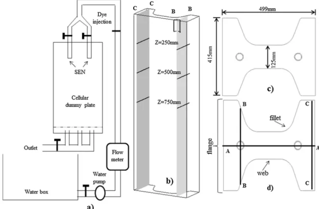
Fig.1.(a)Schematicsof1:1beamblankmodelofamold;(b)isometricviewofthebeamblankwithonenozzle;(c)beamblankdimensions;(d)crosssectionofbeamblank depictingcuttingplanesAA,BB,andCC.
improvetheproductqualityandproductivity,otherconfigurations havebeensuggested.Yangetal.(2004)analyzedthefluidflowin beamblankmoldfittedwithtwonozzles,andfoundthatthe con-figurationofaSENwithafrontalandtwolateraloutlets,withan angleof120◦ betweentheoutletsandaportinclinationof+15◦ leadtobetterinclusionremovalfrommoltensteel.Accordingto Chenetal.(2012b),inthecaseofathreeholeSEN,thesteel pen-etrationdepthwouldbereducedwithasubstantialchangeinthe velocityatthefreesurfaceaccompaniedbyamoreintense fluctu-ation.Thishelpsinthemeltingofthemoldpowderandleadsto abetterabsorptionofnon-metallicinclusions.Therecommended portinclinationangleinthiscasewas+9◦.
Employmentoftwonozzlesinthemoldiscomplexandrequires agoodflowcontrolascomparedtoasinglenozzlearrangement. Nozzle´ısmispositioningcanstimulatenon-symmetricalflow lead-ingtoproductdefects.Ontheotherhand,asinglenozzlefeeding canresultinahighliquidsteelvelocityinthemold,whichis harm-fultotheshellintegrityand meniscusstability.De Santis etal. (2014)proposedin thecase of beamblankcontinuouscasting, feedingthemetalwithonlyonenozzle.Multi-holesnozzle geome-trieshavebeenanalyzedthroughmathematicalmodeling.Anozzle witha50mmdiameterthroat,a50mm×60mmellipticallateral portinclined25◦downwards,anda20mm-diameterbottomhole, hasbeenproposedasthebestSENdesignundertheiroperational conditions.
Asitcanbeseenfromtheabovesurveytheflowfieldinsidethe moldisfundamentalincontrollingtheproductqualityand pro-ductivityandhenceshouldbeoptimizedbycontrollingdifferent variablesrelevanttotheprocess.Inthiscontribution, mathemat-icalandphysicalmodelingofflowfieldinsideabeamblankmold havebeencarriedoutandtheeffectofnozzlegeometry,casting velocityandotherparametershavebeenanalyzed.
2. Methodology
Experimentswereconductedinaphysicalmodel(acrylic)with thefollowingdimensions:499mm×415mm×125mmwiththe moldlengthof 1.5m. Fig.1 representsthephysicalmodel con-structedwithascaleof1:1oftheprototypeofbeamblankmold.The physicalmodelisbasedonsimilaritycriteriabetweentheindustrial steelsystemandamodelemployingwaterastheworkingfluid. ThishasbeendiscussedbySzekelyandIlegbusi(1989). Accord-ingtothem,theisothermalflowsimilarityisachievedifReynolds andFroudedimensionlessgroupsaretakenintoconsideration.A modelwith1:1scaleispreferredconsideringthephysical proper-tiesofwater(25◦C)andsteel(1600◦C)suchasdynamicviscosity anddensity.Hencethemodelvolumetricflowrateisequaltothe volumetricflowrateofsteelintheindustrialunit.Howeverthe effectofagrowingshellandtheconvectivemotionduetovariation oftemperatureinthesteelpoolinthemoldcouldnotbetakenin considerationsincethefluidusedinthephysicalmodeliswaterin isothermalconditions.Thetechniquesinvolvedintheexperiments withthephysicalmodelwereasfollows.
Acontinuousflowofdyewasinjectedinthenozzle.Dye disper-sionwasfollowedbytakingamoviefromwhichdifferentframes fordifferenttimescouldbedetached.Inadditiontodispersion,the penetrationdepthsofliquidjetwerealsomeasured.
J.J.M.Peixotoetal./JournalofMaterialsProcessingTechnology233(2016)89–99 91
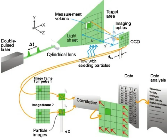
Fig.2. PIV(ParticleImageVelocimetry)accordingtoDANTEC®.
Source:http://www.dantecdynamics.com/measurement-principles-of-piv
Fig.3.Spreadingofadyeinjectedatthetubularnozzleasafunctionoftime.Type1nozzle,liquidflowrateof100L/min—(a)t=1s;(b)t=2s;(c)t=3se(d)t=4s.
Quantitativeanalysisofflowfieldwasmadepossiblethrough the adoption of PIV technique (Particle Image Velocimetry), developed by DANTEC® (Fig. 2). More details of this tech-niquecanbefoundelsewhere(http://www.dantecdynamics.com/ measurement-principles-of-piv).PIVwasemployedtoevaluatethe
73 75 77 79 81 83 85
90 110 130 150
je t pe ne tr at io n de pth (c m )
Liquid flow rate (L/min) Type 1 nozzle
Type 2 nozzle
b)
73 75 77 79 81 83 8590 110 130 150
mc ( ht pe d n oi t ar te ne p te j)
Liquid flow rate (L/min) Type 1 nozzle
Type 2 nozzle
a)
Fig.4.Comparisonbetweenvaluesofpenetrationdepth(a)dyedispersionat2s;(b)CFDresults.
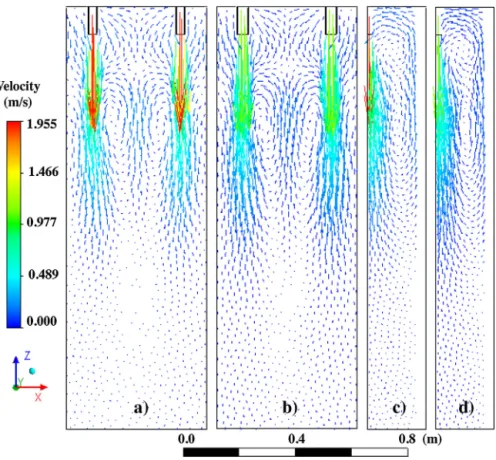
Fig.5.VelocityvectorplotfromCFDforflowrateof125L/min(a)sectionAA,nozzletype1;(b)sectionAAnozzletype2;(c)sectionBBnozzletype1;(d)sectionBBnozzle type2.
Theexperimentalresultsfromthephysicalmodelhasthe objec-tiveofsubstantiatingtheresultsofCFDmodelling,sothatthelatter canbeusedasareliabletoolforimprovementandoptimizationof theprocess.CFDmodelingwasaccomplishedbyusingAnsys®CFX 15.0,assumingisothermalsteadystateconditions.Thestandardk -C
-- turbulencemodelwasused.Thenthefollowingequationshave beensolved:
Continuity:
∂
∂
t +∇
•(U)=0 (1)NavierStokesequation:
∂U
∂t + ∇ •
U⊗ U
− ∇ •eff∇U= −∇p+ ∇ •
eff∇U T+ B (2)
Effectiveviscosityequation:
eff =+t (3)
Equationsofthek-turbulencemodel:
∂
(k)∂
t +∇
•(Uk)=∇
•+t
k
∇
K+Pk−ε (4)∂
(ε)∂
t +∇
•(Uε)=∇
•+t
ε
∇
ε+εk(Cε1Pk−Cε2ε) (5)
t=C
k2
ε (6)
Hereistheliquiddensity(Kg/m3);tisthetime(s);
∇
isthe Nablaoperator;Uistheaveragevelocity(m/s);effistheeffectiveviscosity(Pa.s);Bisthebodyforce(N);isthemolecularviscosity; tistheturbulentviscosity(Pa.s);kistheturbulentkineticenergy
(m2/s2);Pkistherateofproductionofkineticenergydueto
vis-cosityandbuoyancyeffects;εistherateofdissipationofturbulent kineticenergy(m2/s3);Cε1,Cε2,C,kareconstants.
J.J.M.Peixotoetal./JournalofMaterialsProcessingTechnology233(2016)89–99 93
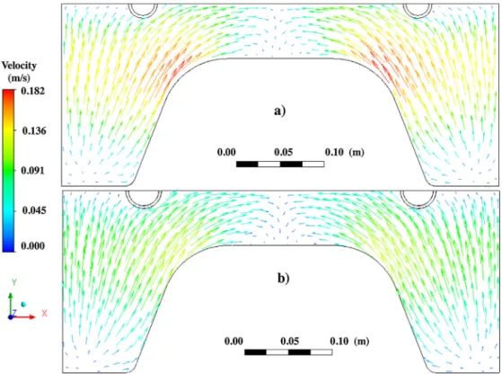
Fig.6.Velocityvectorplotatthemeniscusregionforliquidflowrateof125L/min:(a)type1nozzleand(b)type2nozzle.
Fig.7. VelocityvectorplotsasafunctionofdistanceYfromthemiddleofthenozzle.PIVvaluesatadepthfromthemeniscusof:(a1)250mm,(b1)500mm,(c1)750mm; CFDvaluesatadepthfrommeniscusof(a2)250mm,(b2)500mm,(c2)750mm.Nozzletype1.
•Nonslippingconditionateachliquidsolidinterface,nozzleand
walls.ThenU,kandεvaluesaretakenaszeroattheselocations.
•Freesurfaceconditionatliquidatmosphereinterface,withUw
equaltozero.
•Anaveragevelocityatentrynozzlecanbeestimatedfromthe
respec-Fig.8.VelocityvectorplotatplaneBBforflowrateof125L/min:(a)CFDsimulation;(b)physicalsimulation—PIV.
tively);accordinglyaveragevaluesofkandεhavebeenestimated assuming(Lietal.,2001):
k=0.01V2 (7)
ε= k
1.5
R (8)
whereVistheaverageliquidvelocityatthenozzleinletandRis thenozzleinternalradius.
A simplerapproach to achieve symmetrical flow in a beam blank mold is by using twin tubular nozzles. One single noz-zlealwaysresultsinanon-symmetricalflow.Thetwocasesare detailedhere.Fortwonozzles,symmetricalflow,a combination oftubularnozzlesofdifferentinsidediameters(type1:26.7mm; type2:34.6mm)andcastingvelocities(100L/min,125L/minand 150L/min)havebeenemployed.Thesevolumetricliquidflowrates correspondto the linear casting velocities namely0.78m/min; 0.98m/minand1.2m/min,respectively.Nozzledepthof immer-sionwaskeptat100mm.Physicalandnumericalsimulationsfor onenozzlenon-symmetricalflowhavebeencarriedout consid-eringonetubularnozzlewith53.2mmofinsidediameter(type3 nozzle)atthesameflowrates.Theresultshavebeencompared withthosefromanarrangementwithtwonozzleswith26.7mm insidediameter(type1nozzle).
3. Resultsanddiscussion
3.1. Twonozzles,symmetricalflow
Fluidflowcharacteristicshavebeendeterminedattwocutting planes,AAandBBasshowninFig.1(b) and(d).Themaximum depthreachedbytheincomingliquidjetwasdeterminedusingdye dispersiontechniqueinthemold.Thistechniquehadbeenused byChenetal.(2012b)andZhangetal.(2014).Framesobtained fromdyedispersionexperiments,arerepresentedinFig.3.Itwas observedthatafterroughly2s,dyedispersionwasmainlyinthe horizontaldirection,withaminorinertialcomponentpushingthe dyetowardthebottom.Aframeofdyedispersionat2sofinjection wasusedtodefinethesteelpenetrationdepth.
J.J.M.Peixotoetal./JournalofMaterialsProcessingTechnology233(2016)89–99 95
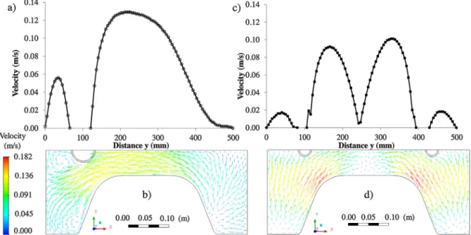
Fig.9.Velocityvectorplotfromydistancefromthecenterofthenozzle,planeBB:PIVatadeepdowndistancefromthemeniscusof(a1)250mm,(b1)500mm,(c1)750mm; CFDsimulationatadeepdowndistancefromthemeniscusof(a2)250mm,(b2)500mm,(c2)750mm.Nozzletype3.
Chenetal.(2012a)havealsofoundthatincreasingflowrates leaded to increasing steel penetration depth. However values obtainedby them were greater than 1m for casting velocities of 0.7m/min to 1.3m/min in the case of a beam blank mold ofdimensions550mm×450mm×90mm,usingtubularnozzles withinternaldiametersfrom40mmto75mmrespectively.The differencecanbeascribedtothemoldgeometry,anarrowerweb andalongerflangeimpairingthefluidflowtowardtheweband thenkeepingtheflowrestrictedtotheflangeregions.
CFD simulationshighlight similar features of theflow field. Fig.5(a)and(b)showsthattheliquidjetspreadsitselftowardthe bottomandthengetsbacktothesurface,generatingtwoeddies inthewebregion.Theliquidmovestotheliquidjetregionand thenisdraggeddown.AlsoinFig.5,onecannoticethepresence oftwoeddiesclosetothesurface.Liquidfromtheseeddiesmoves fromtheflangetothewebandthendownintothejet.This behav-iorissimilartothatfoundbyChenetal.(2012b).Sixeddieswere observedbyZhangetal.(2014).
Nosizableeffectontheoverallfluidflowwasobserved,when changingthenozzleinsidediameterfrom26.7mmto34.6mm.This isseeninFig.5(a)and(b)—planeAA—andinFig.5(c)and(d)—plane BB.Fluidbehaviorissimilarforbothnozzles,althoughjetaverage velocitydecreasesforlargernozzleasexpected.Zhangetal.(2014) alsoobservedthatlargerSENinnerdiameterwouldleadtosmaller liquidlevelfluctuationandanincreaseintheinclusionremoval rate.
Fig.6showsa velocityplotatthemeniscusregion.Onecan noticeaflowfromtheflangestothecentralpartoftheweb.Higher valuesofvelocitywereobservedclosetothefillets.Smallernozzle diameterleadstohighervelocities.Leeetal.(1998)pointedout thattherecirculatoryflowatthewebandatthetipoftheflange
influencesthegrowthofsteelshell.Thegrowthofsteelshellatthe filetregionsisslowerduringtheearlysolidificationstages.Alsothe growthofsolidshellatthefiletregionandatthemiddleoftheweb canberetardedbydirectimpingementofthesteeljetcomingfrom thenozzleupontheshell.
It is important to remember that very low velocities at the meniscusregionare related tosmallerrateofpowder melting, inclusionflotationandremovalbythetopslag.Ontheotherhand excessivevelocityatthemeniscuscanleadtomeniscusoscillation andslagentrapment.DeSantisetal.(2014)suggestedameniscus velocityaround0.30m/sinordertoensuretherequiredpowder meltingrate.AsitcanbeseenfromFig.6,thevaluesofvelocity atthemeniscusarebelowthiscriticalvalue.Enlargingthe noz-zleinsidediametercanfurtherdecreasethevelocity.Thiscould berelatedtosmallervelocitiesattheupperrecirculationeddies showninthevectorplotofFig.5(c)and(d).
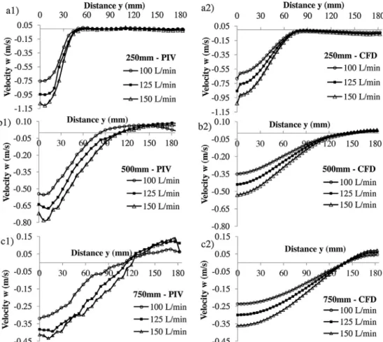
Fig.7showstheverticalcomponentofvelocityinahorizontal measurementlinedrawnthroughtheplaneBB—Fig.1(d).The mea-surementlinesare250mm,500mmand750mmdeep,downthe meniscus.Thisfigureprovidesacomparisonbetweenphysical sim-ulation(PIVvalues,leftside)andCFD(rightside)modelingresults. Largervaluesofvelocityareatthemiddleregion,aroundthecore ofthejetcomingfromthenozzle.Velocitiesdecreasetowardthe walls,asexpected.Thesmallervelocityvaluesintheregion,deep downfromthemeniscusareduetojetspreading.Increasingflow ratesleadtohigherjetvelocity(negativevalues)andto recircula-tion(positivevalues).
Fig.10.VelocityplotsasafunctionofdistanceYatplaneCC.PIVatadeepdowndistancefromthemeniscusof(a1)250mm,(b1)500mm,(c1)750mm;CFDsimulationat adeepdowndistancefromthemeniscusof(a2)250mm,(b2)500mm,(c2)750mm.Nozzletype3.
inorder toensureproductivityrateswithoutcompromisingon qualityandthisshouldnotexceed1.1m/min.Chenetal.(2012a) observedthatwithincreasingthroughputs,thegeneralaspectsof fluidflowinsidethemolddonotchange.However,thesteel pen-etrationdepth,themeniscusvelocityandthesurfaceoscillation doincrease.Allotherparametersbeingconstant,castingvelocity shouldbeintherange0.9m/minto1.3m/min.
Itisworthnoticingthatthechangeofsignofvelocity,asshown inFig.7,isanindicationofaneddy(fromtheflange),asalready showninFig.5(c)and(d).PlotsattheleftsideofFig.7(PIVvalues), showthat thecenterof thiseddyislocatedat75mmfromthe jetcore,some125mmfromthefillet.Ingeneral,thevaluesfrom physicalsimulation(PIV)andfromCFDsimulationsareingood agreement.
3.2. Onenozzlenon-symmetricalflow
Datagatheredfromtheflowfieldhavebeenacquiredinthree measurementplanes:averticalplanecuttingthroughtheweb sym-metryplaneAA,Fig.1(d);averticalplaneparalleltotheflangeand cuttingthroughthecenterofthenozzle,planeBB;andataplane parallelandatadistanceof25mmfromtheotherflange,planeCC. ThisisshowninFig.1(b)and(d).
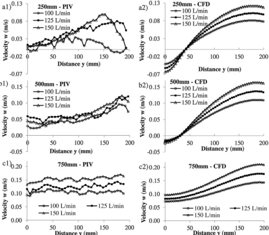
Fig.8showsacomparisonbetweenvelocityvectorplotsfrom physicalmodel(PIVmeasurements)andnumericalCFDmodeling atplaneBB.Theflowstructuresasdepictedfromthese simula-tionsarequitesimilar.Velocityvaluesathorizontallineslocated at250mm,500mmand750mmfromthemeniscus-Fig.1(b)-,at planeBBdeterminedfromexperimentsinphysicalmodel(PIV)and CFDmodelingareshowninFig.9.Bothtechniquessuggestthat thecastingspeeddonotsignificantlychangetheoverallfluid-flow
patternofthejet.ThePIVmeasurementsshowlargervelocities andnarrowerjetsthanthosepredictedbyCFDsimulations.In gen-eral,thereisagoodagreementbetweenthemprovingthattheCFD modelingisareliabletoolforthistypeofprocessanalysis.Velocity valuesatthemiddleregionoftheflangearefoundtobehigher, duetofluidjetcomingfromthenozzle.Higherthroughputsleadto bothhighersteeljetvelocities(downwards)andhigherreturning (upwards)velocitiesattheoppositeflange.
Fig.10representsvelocityvaluesobtainedfromphysicalmodel experiments(PIV)andCFDmodelingatplaneCC-Fig.1(b)-,at hor-izontal lines250mm,500mm,750mmdownthemeniscus.As expected,thevelocityvaluesarecomparativelysmallerthaninthe planeBB.Deeperdownfromthemeniscus,thevelocityincreases duetotheproximityofturningpointoftherecirculationflow.The smallervaluesofvelocityclosetocenteroftheflange,at250mm, areduetoaneddylocatedatthisregion.
Steelpenetrationdepthsforflowratesof100L/min,125L/min and150L/minhavebeendetermined.Thevaluesarerespectively 0.92m,1.19mand1.29mwiththetype3nozzle(53.2mminside diameter). These values are higher than mold nominal length (0.8m).Steelpenetrationdepthsinthecaseoftwotubular noz-zles(type1,26.7mmofinsidediameter)were0.76m,0.81mand 0.84munderthesameconditions.Chenetal.(2012a)hasmadean analysisoffluidflowinsideabeamblankmoldusingtwotubular nozzlesandhasfoundapenetrationdepthof1.09mfora cast-ingvelocityof0.9m/min.Accordingtotheseauthors,ahighvalue ofpenetrationdepthisrelatedtoasmallerlikelihoodofinclusion removal.
J.J.M.Peixotoetal./JournalofMaterialsProcessingTechnology233(2016)89–99 97
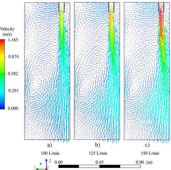
Fig.11.CFDsimulationsofflowfieldatwebsymmetryplaneAA,type3nozzleunderflowratesof:(a)100L/min,(b)125L/minand(c)150L/min.
flangeandlateritisengulfedbythedownwardfluidjet.Attheplane BB,Fig.12(a)–(c),formationoffoureddiescanbenoticed.Twoof themdowninthemoldarealsocausedbythespreadingofthejet andtheothersclosetothenozzleareformedduetothemeetingof thefluidstreamonthefreesurfacewiththefluidengulfedbythe jet.Eddiesalsoappearintheupperregionattheoppositesideof thetubularvalve—planeCC,Fig.12(d)–(f).Theseareformeddueto interactionbetweentheupstreamflowwiththeflowintheregion ofthemeniscus.
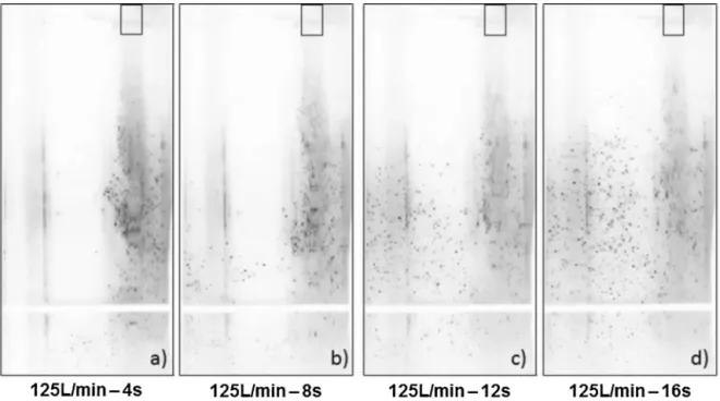
Fig.13showsthemovementofdispersedplasticparticlesinside themoldasafunctionoftimeafterinjection.Theparticleshave beenlitbyalaser sheet.Thejetcanbeconsideredcompleteley developedaftersome12ssincetheparticlesarecompletely dis-persedinthemold.Herealsothereisevidenceforexistanceofthe vortexalreadyshowninFig.11.Theextensionandlocationofthis vortexstructurehavebeenverywellpredictedbyCFDsimulations. Alsoitisclearthatthejetstreamgoesdeepdownto0.8mbefore returningtotheupperportionofthemoldthroughtheopposite flange.
Acomparisonofmeniscusvelocitiesforalinearcastingspeed of0.98m/minand forthe casesof oneand two nozzlesshows noremarkabledifference.Themaximumvaluesare0.15m/sand 0.17m/s, respectively. This is smaller than a limiting value of 0.3m/ssuggestedbyDeSantisetal.(2014).Foronenozzle con-figurationthemaximumvaluecanbefoundattheregionranging fromthewebtothefiletsclosetothenozzle,asit canbeseen fromFig.14(a)and(b).Inthecaseoftwonozzles,themaximum valuesareatthefillets,Fig.14(d).Velocitiesatthewebcenterare ashighas0.09m/s—Fig.14(c).AccordingtoChenetal.(2012a)
toolowmeniscusvelocitycanleadtoalowpowdermeltingrate. XuandZhu(2015)observedthatlowertemperaturesandan inac-tivemeniscusstatusinducedbythestraightSENaffectadversely themeltingthepowderfluxandconsequentlytheproductquality. Beatonetal.(2015)testedonevalvedesignedwithtwopouring holes,oneatthebottomandotheratthelateralsidefacingthe web.TheseauthorsfoundthatwiththisSEN,thecombinedeffect ofevenpowderfeedingandastablemeniscus,resultedinasmooth surfaceoftheproduct,withoutsuperficialholes.
Thehighervaluesofvelocityintheregionbetweenthefiletand thenozzlecanleadtothinnersteelshellatthisregion. Accord-ingtoYangetal.(2004)thefiletregionispronetothinnershells. Thenon-symmetricalflowandthevelocitydifferencesbetween thefiletflowregionscanleadtoshellsofdifferentthicknessatthe fillets.
4. Conclusions
Generally speaking there is a good agreement between the resultsobtainedfromphysicalmodelusingPIVtechniqueandCFD modelling.ThismeansthatCFDmodelingtechniquecanbeused forthistypeofprocessanalysis.Thefollowingconclusionscanbe reachedinrespectofresultsobtainedfortwonozzlesarrangement andthesinglenozzlearrangement:
4.1. Twonozzles,symmetricalflow
•Physicalmodelingshowsastronginfluenceofliquidflowrateon
Fig.12.CFDsimulationsofflowfield,type3nozzleunderflowratesof100,125and150L/min:(a),(b)and(c)planeBB,throughthenozzle,paralleltotheflange,(d),(e) and(f)planeCC,paralleltooppositeflange,250mmfromit.
J.J.M.Peixotoetal./JournalofMaterialsProcessingTechnology233(2016)89–99 99
Fig.14.Velocityvaluesthemeniscus:(a)type1nozzle,(b)type3nozzle.Velocityvectorplotatmeniscus:(c)type1nozzle,(d)type3nozzle.Flowrateof125L/min.
oftheflowrate.Howevertheresultsarecomparablewiththe physicalmodelexperiments.
•Thereisnosignificantchangeinthebehaviorofthefluidflow
whenthenozzleinside diameterischangedfrom26.7mmto 34.6mm.Enlargingthenozzlediameteron68%didnotresult onsizablereductionofthejetpenetrationdepth.
•Therecirculationoffluidgeneratestwoeddiesintheregionof
thewebandtwoineachflange.
4.2. Onenozzlenon-symmetricalflow
•Jetpenetrationdepthwithflowratesof100L/min,125L/minand
150L/min were0.92m,1.19mand1.29m,respectively.These valuesarelargerthanmoldnominallength(0.8m);
•ThereisarecirculationeddydowninthemoldandatplaneBB
foureddiescouldbenoticed;
•Non-symmetricalflowandvelocitydifferencesbetweenthefilet
flowregionssuggestshellsofdifferentthicknessesatthefillets.
Acknowledgement
The authorswish to acknowledgethe help provided bythe researchinstitutionsinBrazilnamelyCNPq,CAPES,Fundac¸ão Gor-ceixandFAPEMIG.
AppendixA. Supplementarydata
Supplementarydataassociatedwiththisarticlecanbefound,in theonlineversion,athttp://dx.doi.org/10.1016/j.jmatprotec.2016. 02.011.
References
Beaton,J.W.,Sgro,A.,Burini,A.,Razza,P.,Azizola,Ali.,2015.Beamblankin submergedpourcasting:Danielitechnologyandexperience.In:Proceedings ofMETECand2ndESTADConference,Düsseldorf,Germany,pp.15–19.
Chen,W.,Zhang,Y.Z.,Zhu,L.-G.,Zhang,C.-J.,Chen,Y.,Wang,B.X.,Wang,C.,2012a. ThreedimensionalFEMstudyoffluidflowinmouldforbeamblank continuouscasting:influenceofstraightthroughconduittypeSEN.Ironmak. Steelmak.39(8),551–559.
Chen,W.,Zhang,Y.Z.,Zhang,C.J.,Zhu,L.G.,Zhang,C.J.,Chen,Y.,Wang,B.X.,Wang, C.,2012b.Three-dimensionalFEMstudyoffluidflowinmouldforbeamblank continuouscontinuouscasting:influenceofnozzlestructureandparameters onfluidflow.Ironmak.Steelmak.39(8),560–567.
DeSantis,M.,Cristallini,A.,Rinaldi,M.,Sgro,A.,2014.Modelling-basedinnovative feedingstrategyforbeamblanksmouldcastingaimedatas-castsurface qualityimprovement.ISIJInt.54(3),496–503.
Hibbeler,L.C.,Xu,K.,Thomas,B.G.,Koric,S.,Spangler,C.,2009.Thermomechanical modelingofbeamblankcasting.IronSteelTechnol.6(7),60–73.
Lee,J.-E.,Yoon,J.-K.,Han,H.N.,1998.3-dimensionalmathematicalmodelforthe analysisbeamblankcastingusingbodyfittedcoordinateofcontinuous system.ISIJInt.38(2),132–141.
Lee,J.-E.,Yeo,T.-J.,Oh,K.H.,Yoon,J.-K.,Yoon,U.-S.,2000.Predictionofcracksin continuouslycaststeelbeamblankthroughfullycoupledanalysisoffluidflow, heattransfer,anddeformationbehaviorofasolidifyingshell.Metall.Mater. Trans.A31A(1),225–237.
Li,B.,Okane,T.,Umeda,T.,2001.Modelingofbiasedflowphenomenaassociated withtheeffectsofstaticmagnetic-fieldapplicationandargongasinjectionin slabcontinuouscastingofsteel.Metall.Mater.Trans.B32B(6),1053–1066. Szekely,J.,Ilegbusi,O.J.,1989.ThePhysicalandMathematicalModellingof
TundishOperations.Springer-Verlag,NewYork,pp.34–38.
Xu,M.,Zhu,M.,2015.Transportphenomenainabeam-blankcontinuouscasting moldwithtwotypesofsubmergedentrynozzle.ISIJInt.55(4),791–798. Yang,J-w.,Du,Y-p.,Shi,R.,Cui,X-c.,Liu,C.,2004.EffectofSENparameterson3D
flowfieldinmouldofbeamblankcontinuouscasters.J.IronSteelRes.Int.11 (6).
Yang,J.W.,Du,Y.P.,Shi,R.,Cui,X.C.,2006.Fluidflowandsolidificationsimulation inbeamblankcontinuouscastingprocesswith3Dcoupledmodel.J.IronSteel Res.Int.13(4),17–21.
Zhang,L.,Chen,D.,Long,M.,Xie,X.,Zhang,X.,Ma,Y.,2014.Hydraulicsimulations offluidflowinbeamblankcastingmoldwithdoublenozzles.In:Yurko,J., Zhang,L.,Allanore,A.,Wang,C.,Spangenberger,J.S.,Kirchain,R.E.,Downey, J.P.,May,L.D.(Eds.),ProceedingsofEPDCongress2014.Hoboken,NJ,USA,pp. 375–384.