Experimental Design and Analysis of a Gyroelastic Beam
Abstract
Gyroscopic systems and their properties have been extensively studied as Angular Momentum Devices (AMD), Control Moment Gyros (CMG) or Gyro-scopes for various applications such as structure control, stability or energy storage. However, most of the works that have been done are theoretical and do not present experimental implementation. In this work we performed an experimental study of a gyroscope beam system (gyroelastic beam) focused systems on the deflection of cantilever beams or the control of flexural stresses. We first used a simple two-degree of freedom model to better un-derstand the terms governing the design, construction and experimental evaluation of gyroelastic beam systems. We then performed experimental tests at different velocities of the gyroscopic actuator and measured the de-flection of the system. The results showed that it is possible to have control of the deflection and the bending forces for this type of configurations which can be exported to helicopter blades or wind turbine blades.
Keywords
Cantilever beam, Gyroscopic moment, Gyroelastic systems.
INTRODUCTION
The study of gyroscopic effects has arisen from the impulse and growth of the aeronautical industry. However, applications of gyroscopic effects have recently been found in biomedical science, robot control, vehicle dynamic control, clean energy, rotating structures, gyroelastic materials or as a means of suppressing vibrations for different structures, among other applications. All structures that present gyroscopic effects or contain one or more gyro-scopes in their structure are called gyroscopic systems. Gyroscopic systems have been extensively studied due to their properties and applications as Angular Momentum Devices (AMD), Control Moment Gyros (CMG) or Gyro-scopes (Meirovitch and Oz, 1980; Meirovitch and Baruh, 1981). Nowadays, there are many mathematical models which have been developed with the purpose of studying the gyroscopic effects or gyroelasticity ranging from ro-tating beams to gyroelastic beam systems with several variants (Peck, 2004; Telli and Kopmaz, 2004; Bai et al., 2008; Yamanaka et al., 1994) in order to analyze airplanes (Zhou et al., 2012), wind turbines (Hamdi et al., 2014; Ma et al., 2015) or unmanned aerial vehicles (UAVs) (Shao et al., 2015). On the other hand, gyroscopic properties have been applied to the design of force sensors (Kurosu and Yamazaki, 2004), biomedical sensors (Nguyen et al., 2014) and cardiac stabilizers (Gagne et al., 2009). The latter have been developed to compensate the movement of the heart at high frequencies and are also intended to aid surgeons and provide support to patients with locomotion difficulties (stability and walking balance) through human-robot interaction (Li and Vallery, 2012). In applications that seek mechanical stability as is the case of boats or aircrafts, bicycles and vehicles have been used for the reac-tion torque of a high-speed flywheel rotating around an axis (Jones and Peck, 2009; Yetkin et al. 2014; Ha and Jung, 2015; Jin et al., 2016). Additionally, the damping properties of gyroscopic systems have been employed in Vehicle
Pedro Cruza*
Enrique Gutiérrezb. Eladio Martínezb
José Ma. Rodríguezb
Rafael Figueroac
Josefa Moralesa
Zaira Pinedaa
a Departamento de Ingeniería Mecánica,
Coordina-ción Académica Región Altiplano, Universidad Au-tónoma de San Luis Potosí, UASLP, Matehuala, San Luis Potosí, México. E-mail: pedro.cruz@uaslp.mx, zaira.pineda@uaslp.mx, josefa.morales@uaslp.mx
b Departamento de Ingeniería Mecánica, Centro
Na-cional de Investigación y Desarrollo Tecnológico, CENIDET, Cuernavaca, Morelos, México. E-mail: esgw@cenidet.edu.mx, mare@cenidet.edu.mx, jmlelis@cenidet.edu.mx
c Departamento de Ingeniería Eléctrica y
Electró-nica, Instituto Tecnológico de Sonora, ITSON, Obre-gón, Sonora, México. E-mail:
rafael.figue-road@itson.edu.mx
*Corresponding author
http://dx.doi.org/10.1590/1679-78254803
Dynamic Control. In some vehicles, gyroscopic properties have been used for energy storage (Flywheel energy stor-age systems or FESS) by means of a high-inertia rotor moving at high speed, especially in hybrid vehicles (Bitterly, 1997; Pullen and Ellis, 2006). Mechanical batteries can outperform electric systems for many applications (Xiao et al. 2011;). Also, the damping properties of gyroscopic systems are used to design a means for suppressing vibra-tions in basic elements such as beams (Chu et al. 2007; Ünker and Çuvalcý, 2015a) or more complex structures such as passenger vehicles (Scheurich et al. 2015) and in the control of seismic movements (Ünker and Çuvalcý, 2015b). Gyroscopic properties have also been used for the generation of clean energies by taking advantage of ocean waves (Wave Energy Converter or WEC). Incident waves activate the precession movement of a gyroscope and the output power is produced by damping the precession movement (Bracco et al. 2012) or by generating their own energy which is used in Marine Vessels (Townsend 2016). Even recently, the concept of gyroelastic materials has been introduced as a class of materials that have continuous distribution of mass, rotational inertia, elasticity, damping and gyricity. Gyroelasticity is the term used for a continuous distribution of angular momentum varying in time (Hassanpour and Heppler, 2014). The theory or concept of gyroelasticity (D’Eleuterio and Hughes,1984; D’Eleu-terio and Hughes, 1987) has given rise to studies on the control of beam structures with a single gyroscope (Hu and Zhang, 2015) and has extended to beams, chains and plates with multiple gyroscopes optimally distributed (Brocato and Capriz, 2009; Hu et al. 2014; Chee and Damaren, 2015; Hassanpour and Heppler, 2016). Thus, various applications of gyroscopic systems are important for industry and research. However, despite major advances in mathematical models of gyroscopic systems and gyroelastic systems, there are few experimental studies due to their complexity. Most of the experimental work focuses on position compensation taking advantage of the stability properties of gyroscopic systems, the main interest being the response of these systems to disturbances that may affect the performance of instruments, vehicles, robots and others. (Gagne et al. 2009, Yetkin et al. 2014, Ha, M. and Jung, S. 2015). The response of gyroscopic systems to a disturbance is a torque that compensates and counteracts the disturbance. This quality has been used experimentally to generate energy from sea waves (Bracco et al. 2012) or to suppress seismic movements (Ünker, F. and Çuvalcı, O. 2015). Regarding gyroelastic beams, no experimental work has been presented showing the results of modifying the dynamic properties (frequency, damping, modal coupling / decoupling) or the effect on cantilever beam deflection or flexural stress control.
In this work we performed an experimental study of a gyroscope-beam system (gyroelastic beam). The exper-imental tests were conducted at different speeds of the gyroscopic actuator while measuring the deflection of the system.
2 SIMPLE MATHEMATICAL MODEL OF A GYROSCOPE-BEAM SYSTEM
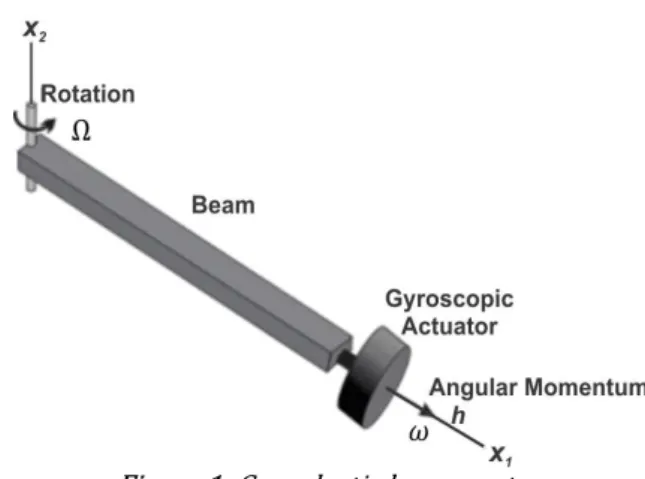
Consider the gyroscope-beam system (gyroelastic beam) shown in Figure 1. The physical model is composed of a beam of a rectangular uniform cross-section and a gyroscopic actuator. The beam rotates in a horizontal plane and a gyroscopic actuator of variable velocity is mounted on the free end (Hu and Zhang, 2015). The beam rotates in a horizontal plane about the vertical axis x2. The actuator disc rotates in a plane perpendicular to the longitudinal axis of the beam. With this configuration it is possible to control the quantity of the system’s angular movement (h) and consequently control the magnitude of the gyroscopic moment (Peck, 2004; Joubert et al. 2007).
Figure 1: Gyroelastic beam system
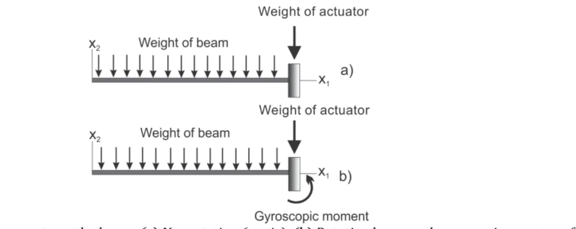
Figure 2: Loads and moments on the beam: (a) Nonrotating (static). (b) Rotating beam and gyroscopic actuator effect
The weight of the beam is represented as a uniformly distributed downward load. When the beam rotates around the vertical axis x2, tension is produced on the inside caused by centripetal forces (which in this work we now call inertial force) that keeps it attached to the axis of rotation (Simpkinson et al. 1948). As a result of this tension, the free end is raised a distance that is a function of the mass and length of the beam and its rotation speed or processional speed (𝛺). In addition to the weight and the forces caused by the rotation of the beam, a gyroscopic moment acts on the free end of the beam. This moment is produced by the actuator which is mounted over the beam and rotating with constant angular velocity(𝜔) around the longitudinal axis of the beam (Figure 2). The gy-roscopic moment is proportional to: i) the moment of inertia and the angular velocity of the actuator (𝜔), and ii) the angular speed of rotation of the beam around the vertical axis (𝛺). The directions of rotation of the beam and the actuator should be chosen so that the gyroscopic moment produces an elevation of the beam.
When the gyroscopic actuator and the beam are in motion, the forces and moments that act on the beam do not vary with time viewed from a fixed frame of reference. Thus, the relationship between the loads applied to the beam and the deformations that are produced can be studied by using static methods. There are three types of loads acting on the rotary beam: i) the weight of the beam and the gyroscopic actuator weight, ii) the inertial forces caused by the rotating beam and iii) the gyroscopic moment generated by the actuator.
The gyroelastic beam can be expressed through a simple two-degree-of-freedom model under the following assumptions: 1) the axes of the inertia of the beam coincide with the coordinate axes x1 and x2 (the angular mo-mentum vector provided by the gyroscopic actuator is always directed to the neutral axis of the beam); 2) the mass of the beam is much smaller compared with the tip mass, 3); and the axial displacement of the beam is neglected in comparison to the transverse ones (Sinha et al., 2013). This model enabled us to examine the terms of the equations of motion for their physical interpretation such as the following:
𝑚𝐿 𝑥 + 𝑐𝑥′ − ℎ𝑥 + 𝑥 = 0 (1)
𝑚𝐿 𝑥′′ + ℎ𝑥′ + 𝑐𝑥′ + 𝑥 = 𝑊𝐿 (2)
Where, 𝑚 is the beam mass, 𝐿 is the beam length 𝑊 is the weight of the gyro actuator, 𝑐 is the damping, 𝐸 is the Young's module, and 𝒉 is the angular momentum.
The above equations can be rewritten as:
𝑚𝐿 0
0 𝑚𝐿 𝑥′′𝑥′′ + ℎ𝑐 −ℎ𝑐 𝑥′𝑥′ +
0 0
𝑥
𝑥 = 𝑊𝐿 0 (3)
The matrices from (Eq.3) are given by:
𝑴= 𝑚𝐿0 𝑚𝐿0 , 𝑮 = 𝑐 −ℎℎ 𝑐 , 𝑲 = 0
0 , 𝑸 = 0𝑊𝐿 , 𝑿 = 𝑥′′
𝑥′′ , 𝑿 = 𝑥′𝑥′ , 𝑿 = 𝑥𝑥
represents the vector components of beam deflection (displacement). The 𝑮 matrix contains a discrete mechanical damper (of damping coefficient c) and h that is the angular moment of beam; this matrix is also called the gyroscopic matrix (G). Considering the gyroelastic beam system is not affected by external damping (𝑐 = 0) Equations 1 and 2 can be expressed as:
𝑚𝐿 𝑥 − ℎ𝑥 + 𝑥 = 0- (4)
𝑚𝐿 𝑥′′ + ℎ𝑥′ + 𝑥 = 𝑊𝐿 (5)
As shown above, elements −ℎ𝑥′ and ℎ𝑥′ couple the movement between both axes and therefore the equa-tions, as is characteristic of gyroscopic systems. It is observed that deflection of the free end of the beam with re-spect to its no-load position is given only in the x2 axle (see Figure 1); therefore, the axial displacement of the beam is neglected in comparison to the transverse ones. The main interest is to analyze the effects of the gyroscopic mo-mentum on the axis of greater deflection. From Equations 4 and 5 only the terminus on the x2-axis is taken. Then these equations can be rewritten as:
−ℎ𝑥 = 0 (6)
𝑚𝐿 𝑥 + 𝑥 = 𝑊𝐿 (7)
Equation 6 represents the gyroscopic moment (𝐼 𝜔𝛺). Similarly, first term in Equation 7 is the inertial o cen-trifugal moment (𝑚𝐿 𝛺), while the second and last terms denote the moment of flexion and the moment generated by the weight of the gyroscopic actuator, respectively.
3 PARAMETER SELECTION IN THE DESIGN PROCESS
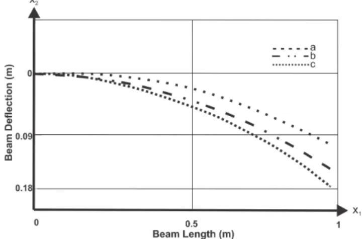
The magnitude of the gyroscopic moment generated by the gyroscopic actuator depends on the moment of inertia, the angular velocity of the actuator (ù) and the angular speed of the beam (precession speed) (Ω). The goal in the design of a gyroscopic actuator is to produce the maximum gyroscopic moment with the lowest weight. Some design parameters such as the geometric and elastic properties as well as the location of the actuator along the beam do not affect the magnitude of the gyroscopic moment generated by the actuator. However, these determine the levels of deformation and stresses that occur in the beam. Equations 6 and 7 have been solved analytically in different ranges of 𝐿, Ω, ù and 𝐼 . Using this information it is possible to determine the optimum values of these parameters. Such values were selected according to the desired beam length values as well as the elastic limit, an-gular velocity and weight of the actuator. The anan-gular velocity of the gyroscopic actuator is important because the magnitude of the gyroscopic moment has a directly proportional variation to it. Figure 3 shows the simulation of the vertical static deflection of the beam as a function of its length under load conditions considered in the model. Curve (c) shows the beam is state of rest (Ω=0) and the gyroscopic actuator is disabled (h=0); in Curve (b) the effects on the deflection of the beam caused by the inertial forces are shown (Ω≠0) and there are no gyroscopic moments (h=0) under these conditions; thus, the gyroscopic actuator behaves as a mass concentrated on the free end of the beam. The effects on the deflection of the beam caused by the inertial forces (Ω≠0) and the gyroscopic moment (h≠0) are shown in curve (a).
Figure 3: The elastic curves on the beam: rotation of the beam and gyroscopic moments
The experimental studies presented in Section 1 operate in the approximate range of 9000 - 20000 rpm. In this study the actuator angular velocities between 0 and 20000 rpm were considered in order to analyze the effects of the gyroscopic actuator on the deflection of the beam over a wide range. In all cases, the precession rate is as-sumed constant. From simulation results, the deflection on the free end of the beam as a rotational angular velocity function of the actuator is plotted in Figure 4. The rotation direction of the actuator was chosen in such a way that the moment generated by the gyroscopic actuator tended to bend the beam upward counteracting the effects of its weight. With the actuator deactivated at 0 rpm, the downward (negative) deflection is maximum when the speed of the actuator increases. The magnitude of gyroscopic moment counteracts this deflection, which is completely eliminated at close to 19000 rpm. The deflection is upward (positive) for velocities above this value.
Figure 4: Deflection vs. velocity actuator with constant angular speed of precession
Figure 5: Deflection on the free end of the beam as a function of its length.
Figure 6: Deflection on the free end of the beam as a function of its length.
Beam selection is important because a beam needs to have stiffness properties that enable observation of gy-roscopic moments. Thus, if the beam is very rigid, the gygy-roscopic moments will become internal stresses with minor displacements; deformation in these displacements is difficult to detect by a position measuring system. In this study, a beam with geometry and dimensions that allows for the generation of a significant displacement was se-lected. The beam used for experimentation was 1.5 m in length; however, its length can vary by sliding over its support. Mainly, we worked with a length of 1 m in order to avoid working in the plastic region of the beam (Ha and Jung, 2015; Hu and Zhang, 2015; Chee and Damaren, 2015). The values obtained for the experimental design are shown in Table 1.
Table 1: Physical properties of the system
Property Symbol Numerical Values
Young’s modulus 𝐸 205𝑥10 𝑚𝑁
Beam thickness 𝑎 3𝑥10 𝑚
Beam width 𝑏 25𝑥10 𝑚
Length of the beam 𝐿 1𝑚
Beam mass 𝑚 0.386𝑘𝑔
Moment of inertia of
Gy-rocopic actuator 𝐼 3.54𝑥10 𝑘𝑔. 𝑚
Geometrical moment of
inertia 𝐼 5.62𝑥10 𝑚
Area of cross section A 7.5𝑥10 𝑚
Disk mass of gyroscope m 0.350𝑘𝑔
Angular momentum h 0 − 7.42𝑘𝑔𝑚𝑠
Rotating speed of the beam (processional
speed) Ω 0 − 50 𝑟𝑝𝑚
Angular velocity of
3.1 Gyroscopic actuator design
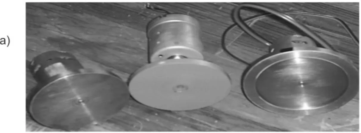
Based on the results obtained from the previous section, an initial gyroscopic actuator was constructed and coupled with a DC motor operating in an angular velocity ranging from 0 to 40,000 rpm. The actuator was used in the first experimental tests, where it was determined that the weight of the actuator causes excessive static defor-mation on the beam. In order to solve this problem, a second actuator was built with the purpose of reducing its weight and increasing its moment of inertia; however, it was only possible to increase the moment of inertia by keeping the same weight (Figure 7a). New alternatives to the gyroscopic actuator design were investigated in order to reduce their weight. The first point that was analyzed was the weight of the DC motor because a large part of it belonged to the gyroscopic actuator. Following this, the new gyroscopic actuator was designed and built (Figure 7b). This figure shows the final assembly of the gyroscopic actuator, which is composed of an inertial rotor, a pair of bearings and a link as a flexible shaft.
Figure 7: a) Explored design alternatives for the gyroscopic actuator, b)Final assembly of rigid beam actuator
3.2 Test Bench Construction
Figure 8: a) Rigid rotating platform and slip rings b) Eddy current transducer
Figure 9 shows the block diagram and the function performed by each component of the gyroelastic system. In the system, u represents the voltage input, ù as stated above represents the motor speed of the gyroscopic actu-ator depending on the input voltage (u), h represents the gyroscopic momentum, which affects the deflection of the beam represented by x2. This deflection represents the output of the system, which is the variable of interest in this work.
Figure 9: Block diagram for deflection control
The Figure 10 shows the schematic diagram of the measurement process where the input voltage defined by the operator (u) is used to regulate the speed of the gyroscopic actuator motor, thus allowing the control of the deflection of the beam (x2). Deflection is captured through the displacement sensor through an acquisition system and a computer that displays the results of the deflection at the beam (x2) and the speed of the gyro actuator (ù).
4 EXPERIMENTAL RESULTS
Tests were carried out using a flexible beam (see Figure 8) for two precession rates (Ω) (42 and 50 rpm) with five stages of gyroscopic actuator velocity ranging from 0 to 20000 rpm. Experimental values obtained for the de-flection of the beam are shown on Figure 11. This Figure shows the beam dede-flection for some stages of the gyro-scopic actuator velocity, with the following meanings:
Curve represents the static deflection of the beam without a rotation effect or gyroscopic moment. Curve represents the deflection of the beam when the beam is rotating; the beam is affected by the inertial force in its rotational speeds. The gyroscopic moment is not involved in this stage.
Curve represents the deflection affected by the inertial force and the gyroscopic moment at the free end of the beam.
Figure 11: Experimental beam deflections for 42 and 50 rpm angular speed
Table 2: Magnitude of the gyroscopic moments with respect to the angular speed of the beam and the angular velocity of the gyroscopic actuator
Angular
speed(rpm) Angular velocity (rpm)
Gyroscopic Moment
(N.m)
Angular
speed(rpm) Angular velocity (rpm)
Gyroscopic Moment
(N.m)
42 rpm
0 0
50 rpm
0 0
6000 0.3387 6000 0.8382
8000 0.8618 8000 1.2127
15000 1.3195 15000 1.5098
20000 2.2151 20000 2.3004
As shown in Table 2, the magnitude of the gyroscopic moments generated under experimental conditions is small. Its greatest magnitude occurs when the condition of angular speed of the beam is 50 rpm and the angular velocity of the gyroscopic actuator is 20000 rpm. The magnitude of the gyroscopic moment is equivalent to 2.30 N.m; such magnitude is small, though it helps to counteract the bending moments, which are caused by actuator weight and the beam’s weight distribution.
In addition to the gyroscopic moments, inertial moments are also generated due to the inertial force when the gyroscope-beam system is in rotation. In Table 3, the inertial moments and the gyroscopic moments are compared with the gyroscopic moments registered during the steps of the actuator velocity.
Table 3: Comparison: inertial moment – gyroscopic moment
Angular
speed(rpm) Angular velocity (rpm) Iner-tial mo-ment (N.m) Gyro-scopic Mo-ment (N.m) Angular
speed(rpm) Angu-lar veloc-ity (rpm) Iner-tial mo-ment (N.m) Gyro-scopic Mo-ment (N.m) 42 rpm 0 0.9649 0 50 rpm 0 1.7137 0
6000 0.3387 6000 0.8382
8000 0.8618 8000 1.2127
15000 1.3195 15000 1.5098
20000 2.2151 20000 2.3004
The moments caused by inertial forces are constant during the rotation of the beam. It is important to observe that in the first two stages the moment caused by inertial force is greater than the gyroscopic moment. On other hand, in the last two stages the gyroscopic moment is greater than the moment caused by the inertial force.
5 DISCUSSION
The experimental results showed that in some stages the moments produced by the forces of inertia are greater than the gyroscopic moments generated by the actuator. However, these results do not occur in the later stages because the gyroscopic moments have greater magnitudes than the others, which help to counteract the deflection of the beam to around 55 percent of the initial deflection. The experimental results vary in comparison to the ex-pected theoretical results (Figures 4, 5 and 6). Table 4 shows the variations in the results obtained.
Table 4: Variations in the results obtained
Angular
speed(rpm) velocity (rpm) Angular Theoretical deflection (m) Experimental deflection (m)
42 6000 0.05 0. 013
50 6000 0.027 0.098
This is because of considerations taken from the theoretical model shown in Section 2. The condition with the greatest effect on these results is the one that states that the axes of the inertia of the beam coincides with the coordinate axes x1 and x2 (the angular momentum vector provided by the gyroscopic actuator is always directed to the neutral axis of the beam). In the case of experimentation, the angular momentum vector moves approximately 2 cm parallel to the neutral axis of the beam and deviates 16° from the horizontal at maximum beam deflection. Therefore, a decomposition of the angular momentum vector into its vertical and horizontal components is pre-sumed; thus, for theoretical calculation, the horizontal component was taken parallel to the neutral axis of the beam. In reality, due to the decomposition of the vector, the horizontal field of the vector is much better than the one considered theoretically. The discrepancy between theoretical and experimental results is mainly attributed to de-composition of the angular momentum vector. Li et al. (2000) propose a mathematical model that considers changes in the orientation of angular momentum vector in a flexible link with a tip rotor resulting in a very complex solution of the model, which was not our purpose. With the simple model we presented, we were able to plan the experimental stage and measure the components such as the gyroscopic actuator and the beam. It would certainly be of great interest in the future to develop a mathematical model that considers the decomposition of the angular momentum vector, in addition to the varying forces in time such as inertial and gravitational forces during experi-mentation. Other possible causes of the difference between theoretical and experimental results may be noise in the measurement signals generated by the use of slip rings.
6 CONCLUSIONS
The experimental behavior of a gyroelastic beam was investigated and presented in this work. Tests carried out using a flexible beam and a gyroscopic actuator where two precession rates (42 and 50 rpm) and five stages of gyroscopic actuator velocity ranging from 0 to 20000 rpm were analyzed. The maximum values obtained from the results of the gyroscopic moments were 2.21N.m and 2.3 N.m for each of the precession speeds. These moments helped to counteract the deflection of the beam to around 55 percent of the initial deflection. These results confirm the benefits of the use of the gyroscope actuator on cantilever beam systems. A simple mathematical model of a gyroscope beam system was used to obtain the design and construction parameters of the beam and the gyroscopic actuator. However, as an open problem, it would certainly be of great interest in the future to develop a more com-plete mathematical model that accurately represents the conditions presented in a gyroelastic beam system. Finally, in contrast with other works published in the literature, this study presents experimental evidence on the benefits of the gyroscopic actuator (CMG) as a viable alternative to reduce and control the magnitude bending stress through the control of deflection on cantilever beam systems (i.e. turbine blades or helicopter blades).
References
Bai, S., Tzvi, P., Zhou, Q. and Huang, X. (2008). Dynamic Modeling of a Rotating Beam Having a Tip Mass. IEEE Inter-national Workshop on Robotic and Sensors Environments. pp. 52-57.doi: 10.1109/ROSE.2008.4669180.
Bitterly, J. (1997). Flywheel Technology Past Present and 21 Century Projections. IECEC-97 Proceedings of the Thirty-Second Intersociety Energy Conversion Engineering Conference (Cat. No.97CH6203). pp. 2312-2315 vol.4. doi: 10.1109/IECEC.1997.658228.
Bracco, G., Giorcelli, E., Mattiazzo, G., Pastorelli, M. and Raffero, M. (2012). Testing of a Gyroscopic Wave Energy System. Renewable Energy Research and Applications (ICRERA), International Conference on. doi: 10.1109/ICRERA.2012.6477443.
Brocato, M. and Capriz, G. (2009). Control of Beams and Chains Through Distributed Gyroscopes. AIAA Journal. Vol. 47, No. 2, pp. 294-302. http://dx.doi.org/10.2514/1.29250.
Chee, S. and Damaren, C. J. (2015). Optimal Gyricity Distribution for Space Structure Vibration Control. Journal of Guidance, Control, and Dynamics, Vol. 38, No. 7 (2015), pp. 1218-1228. https://doi.org/10.2514/1.G000293
D’Eleuterio, G. M. T. and Hughes, P. C. (1987). Dynamics of Gyroelastic Spacecraft. J. Guid. Control Dyn., 10(4), pp. 401–405.http://dx.doi.org/10.2514/3.20231.
D’Eleuterio, G. M. T. and Hughes, P. C. (1984). Dynamics of Gyroelastic Continua. J. Appl. Mech 51(2), 415-422. doi:10.1115/1.3167634.
Gagne, J., Laroche, E., Piccin, O. and Gangloff, J. (2009). An active cardiac stabilizer based on gyroscopic effect. Conf Proc IEEE Eng Med Biol Soc.6769-72. doi: 10.1109/IEMBS.2009.5332512.
Ha, M. and Jung, S. (2015). Balancing control application using gyroscopic effect to a hand-carried one-wheel cart. IEEE International Conference on Advanced Intelligent Mechatronics (AIM), pp.1778-1782. doi: 10.1109/AIM.2015.7222804.
Hamdi, H., Mrad, C., Hamdi, A. and Nasri, R. (2014). Dynamic response of a horizontal axis wind turbine blade under aerodynamic, gravity and gyroscopic effects. Applied Acoustics. Volume 86, Pages 154– 164.http://dx.doi.org/10.1016/j.apacoust.2014.04.017.
Hassanpour, S. and Heppler, G. (2014). Dynamics of micropolar gyroelastic materials. Proceedings of the 9th Inter-national Conference on Mechanics of Time-Dependent Materials. At Montreal, QC, Canada. doi: 10.13140/RG.2.1.1213.4169.
Hassanpour, S. and Heppler, G. R. (2016). Dynamics of 3D Timoshenko gyroelastic beams with large attitude changes for the gyros. Acta Astronautica, 118, pp.33-48. doi:10.1016/j.actaastro.2015.09.012
Hu, Q. and Zhang, J. (2015). Placement optimization of actuators and sensors for gyroelastic body. Adv.Mech.Eng.7(3). Pp 1–15. http://dx.doi.org/10.1177/1687814015573765.
Hu, Q., Jia, Y. and Xu, S. (2014). Dynamics and vibration suppression of space structures with control moment gyro-scopes. Acta Astronautica. Volume 96, March–April 2014, Pages 232–245. doi:10.1016/j.actaastro.2013.11.032.
Jin, H. Wang, T., Yu, F., Zhu, Y., Zhao, J. and Lee, J. (2016). Unicycle Robot Stabilized by the Effect of Gyroscopic Precession and Its Control Realization Based on Centrifugal Force Compensation. IEEE/ASME Transactions on Mechatronics, vol. 21, no. 6, pp. 2737-2745. doi: 10.1109/TMECH.2016.2590020.
Jones, L. and Peck, M. A. (2009). A generalized framework for linearly-constrained singularity-free control moment gyro steering laws. AIAA Guidance, Navigation, and Control Conference, 10–13. Aug 2009, Chicago, Illinois. http://dx.doi.org/10.2514/6.2009-5903.
Joubert, S., Fedotov, I., Pretorius, W. and Shatalov, M. (2007). On gyroscopic effects in vibrating and axially rotating solid and annular discs. International Conference - Days on Diffraction. St. Petersburg, pp. 89-94. 10.1109/DD.2007.4531995.
Kurosu, S. and Yamazaki, T. (2004). Gyroscopic Force Measuring System —Theory and Applications. SICE Annual Conference in Sapporo, August 4-6,2004. Hokkaido Institute of Tecnology, Japan.
Li, D. and Vallery, H. (2012). Gyroscopic assistance for human balance. 12th IEEE International Workshop on Ad-vanced Motion Control (AMC), pp. 1-6. doi: 10.1109/AMC.2012.6197144.
Ma, H., Lu, Y., Wu, Z., Tai, X., Li, H. and Wen, B. (2015). A new dynamic model of rotor–blade systems. Journal of Sound and Vibration, Volume 357, Pages 168–194.http://dx.doi.org/10.1016/j.jsv.2015.07.036.
Meirovitch, L. and Oz, H. (1980). Modal-Space Control of Distributed Gyroscopic Systems. Journal of Guidance, Con-trol, and Dynamics, Vol. 3, No. 2. pp. 140-150. http://dx.doi.org/10.2514/3.55961.
Meirovitch, L. and Baruh, H. (1981). Optimal control of damped flexible gyroscopic systems. Journal of Guidance and Control, 4(2):157-163.
Nguyen, T., Ranieri, M., DiGiovanna, J., Peter, O., Genovese, V., Pérez, A. and Micera S (2014). A real-time research platform to study vestibular implants with gyroscopic inputs in vestibular deficient subjects. IEEE Trans. Biomed. Circuits Syst., vol. 8, no. 4, pp. 474-484. doi: 10.1109/TBCAS.2013.2290089.
Peck, M. (2004). Practicable Gyroelastic Technology. 27th Annual AAS Guidance and Control Conference. Paper No. AAS 04-023. Breckenridge, CO.
Pullen, K. and Ellis, C. (2006). Kinetic Energy Storage for Vehicles. IET - The Institution of Engineering and Technol-ogy Hybrid Vehicle Conference. pp. 91-108. doi: 10.1049/cp:20060616.
Scheurich, B., Koch, T., Frey, M. and Gauterin, F. (2015). Damping A Passenger Car With A Gyroscopic Damper Sys-tem. SAE Int. J. Passeng. Cars - Mech. Syst. 8(2). Detroit, Michigan, USA. doi:10.4271/2015-01-1506 .
Shao, P., Dong, W., Sun, X., Ding, T. and Zou, Q. (2015). Dynamic Surface Control To Correct For Gyroscopic Effect Of Propellers On Quadrotor . Information and Automation, IEEE International Conference on. pp. 2971-2976. doi: 10.1109/ICInfA.2015.7279797.
Simpkinson, S. H., Eatherton, L. J. and Millenson, M. B. (1948). Effect of Centrifugal Force On The Elastic Curve Of A Vibrating Cantilever Beam. NACA Report 914. Cleveland, Ohio.
Sinha, A., Bose, S., Nandi, A., Neogy, S.(2013). A precessing and nutating beam with a tip mass. Mechanics Research Communications,Volume 53, Pages 75-84,ISSN 0093-6413, https://doi.org/10.1016/j.mechrescom.2013.08.006.
Telli, S. and Kopmaz, O. (2004). On the Mathematical Modelling of Beams Rotating About A fixed Axis. Mathematical and Computational Applications 9 (3), 333-348. doi:10.3390/mca9030333.
Townsend, N. (2016). Self-powered autonomous underwater vehicles: results from a gyroscopic energy scavenging prototype. IET Renewable Power Generation, Volume: 10, pp. 1078-1086. Issue: 8. doi: 10.1049/iet-rpg.2015.0210.
lÜnker, F. and Çuvalcý, O. (2015a). Vibration Control of a Column Using a Gyroscope. Procedia - Social and Behav-ioral Sciences. Volume 195, 3 July 2015, pages 2306-2315. https://doi.org/10.1016/j.sbspro.2015.06.182.
Ünker, F. and Çuvalcý, O. (2015b). Seismic Motion Control of a Column Using a Gyroscope. Procedia - Social and Behavioral Sciences 195:2316 – 2325.
Xiao, Y., Zhang, C., Zhu, K. and Ge, X. (2011). Suppression of gyroscopic rotation in flywheel energy storage systems. In Proc. Proceedings of the 2011 Chinese Control and Decision Conference. Pp. 3286-3289, Shenyang, China.
Yamanaka, K., Heppler, G. R., Huseyin, K. (1994). The Stability of a Flexible Link with a Tip Rotor and a Comprehen-sive Tip Load. IEEE Transactions on Robotics and Automation, Vol. ICRA 1994: 1798-1803.