UNIVERSIDADE DA BEIRA INTERIOR
ENGENHARIA
Development and Testing of a Variable-Spam
Morphing Wing
João Miguel Inácio Felício
Dissertação para obtenção do Grau de Mestre em
Engenharia Aeronáutica
(2º ciclo de estudos)
Orientador: Prof. Doutor Pedro Gamboa
i
Abstract
Motivation for the work.
The present work focuses on the development and validation of a variable-span morphing wing (VSW) to be fitted to a mini UAV. An electro-mechanical actuation mechanism is developed using a simple rack and pinion system. The wing model is designed with the help of graphical CAD/CAE tools and then a full scale model is built for bench testing the strength, power consumption, deployment time and efficiency. The concepts used on the morphing wing for both fixed and moving wing parts are considered simple and effective. Construction methods and materials were evaluated in order to obtain a system as reliable as possible. Still, in future work the VSW structure can be improved by changing some interface components to achieve a smoother deployment. Also, some work is planned on the design optimization code: implementation of a coupled aero-structural analysis model for simultaneous aerodynamic and structural design optimization problems.
ii
Resumo
O presente trabalho apresenta o desenvolvimento e ensaio de uma asa de envergadura variável actuada por um sistema electromecânico simples para aplicação no UAV “Olharapo”. Um mecanismo de accionamento electromecânico é desenvolvido com base num sistema de cremalheira e pinhão. O modelo da asa é projectado com a ajuda de ferramentas gráficas CAD / CAE e, em posteriormente, é construído um modelo em escala para ensaios quanto a resistência, consumo de energia, tempo de extensão/retracção e eficiência. Os conceitos utilizados na asa morphing para ambas as partes, fixas e móveis, da asa são consideradas simples e eficazes. Foram avaliados métodos e materiais de construção no intuito de obter um sistema mais fiável e eficaz. Ainda assim, em trabalhos futuros a estrutura VSW pode ser melhorada alterando alguns componentes de interface para conseguir uma actuação mais suave e eficaz. Além disso, é previsto no código de optimização de envergadura capaz de controlar esta em função da velocidade.
iii
Acknowledgments
I would like to thank Dr. Pedro Gamboa for his continuous support and motivation. Without his guidance this project would not have been possible.
Also, I want to thank my parents for their strength in believing me in this chapter of my life. Finally, I want to thank to Marta for her indispensable help, support and understanding.
iv
List of Figures
Figure 1.1 – Different flight configurations of a bird. ... 1
Figure 1.2 – B-1, F14 and F-111 aircrafts images. ... 2
Figure 1.3 – Akaflieg FS-29 blueprint. ... 3
Figure 1.4 –Drag comparison between original and VSW. ... 6
Figure 1.5 – Roll rate variation for flight speeds of 15, 20 and 25 m/s. ... 6
Figure 1.6 – VSW mounted on Olharapo’s fuselage. ... 7
Figure 1.7 – Deployment sequence. ... 8
Figure 1.8 - Wing configurations for high-lift, climb, cruise, loiter, and maneuver. ... 11
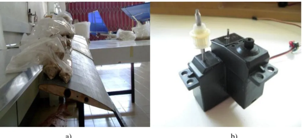
Figure 2.1 and 2.2 – VSW on bench test and servo mechanism respectively. ... 14
Figure 2.3 – Bubbles and wrinkles on IFW’s surface. ... 15
Figure 3.1 – Scheme of the various materials involved in the vacuum lamination. ... 20
Figure 3.2 – Construction detail of (a) the balsa web and (b) the carbon flange. ... 21
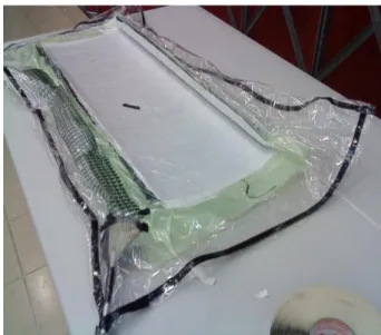
Figure 3.3 – Vacuum bagging final installation. ... 21
Figure 3.4 – External mold used to manufacture OMW’s shell. ... 22
Figure 3.5 – Ribs cutting mold. ... 22
Figure 3.6 – Demonstration of the results using technique (a) (right) and (b) (left). ... 23
v
Figure 3.8 – Detail view of the rack supported by OMW’s structure (CAD drawing). ... 24
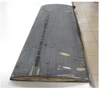
Figure 3.9 – First carbon layer after phase 1. ... 26
Figure 3.10 – Outcome after the use of epoxy resin in the interface carbon-PVC foam. ... 27
Figure 3.11 – Skin during the second phase 2. ... 27
Figure 3.12 – Parts of the PVC foam. ... 28
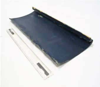
Figure 3.13 – Picture of the skin in the phase 3. ... 28
Figures 3.14 – Picture of the skin after phase 3. ... 29
Figure 3.15 – Corrections made on the previous IFW. ... 29
Figure 3.16 – Generic view of the rack. ... 30
Figure 3.17 – Original rack, rack with the desired length and rack with the desired cross section. ... 31
Figure 3.18 – Rack and pinion (left) and rack (right). ... 32
Figure 3.19 – Servo HS-805MG, views (left) and open servo (right). ... 32
Figure 3.20 – Original potentiometer to servo configuration. ... 33
Figure 3.21 – Servo’s shaft. ... 34
Figure 3.22 – Diagram of reduction stages. ... 34
Figure 3.23 – Detailed views of reduction stages. ... 35
Figure 3.24 – Central fuselage part. ... 35
Figure 3.25 – Rollers and rack detail (CAD drawing). ... 36
Figure 3.26 – Actuation bay. ... 36
Figure 4.1 – Assembly used for structural and system evaluation tests. ... 38
Figure 4.2 – Bending test. ... 39
Figure 4.3 – Gap between upper skins. ... 40
vi
Figure 4.5 – Installation used in maximum actuation force test. ...41
Figure 4.6 – IFW load, equivalent wing tip load and total load as function of load factor. ...42
Figure 4.7 – Retraction and extension times for load factors, with and without ball bearings. ...43
Figure 4.8 – example of the e-logger readings for the 4g case. ...44
Figure 4.9 – Power consumption test assembly. ...44
Figure 4.10 - Assembly to test the mean force. ...45
vii
List of Tables
Table 1.1 – FS-29 specifications. ... 3
Table 1.2 – Deployment test results. ... 8
Table 3.1 – Characteristics of HS-805MG servo. ... 33
Table 3.2 – Summary of the final component weights and original Olharapo’s Wing. ... 37
Table 4.3 – Consumption and efficiency test results. ... 47
viii
Nomenclature
b Wng Spam
Drag Coefficient Airfoil Coefficient IFW Inner Fixed Wing
Lift
Lift to Drag Ratio
UAV Unmanned Aerial Vehicle VSW Variable Spam Wing
ix
Index
Abstract ... i Resumo ... ii Acknowledgments ... iii List of Figures ... ivList of Tables ... vii
Nomenclature ... viii
Index ... ix
Chapter 1 ... 1
Introduction ... 1
1.1. State of the art ... 2
1.1.1. Akaflieg FS-29 ... 2
1.1.2. Telescopic spars ... 3
1.1.3. Recent design and development of telescopic wings ... 5
1.1.4. Inflatable wings ... 8
1.1.5. Next Generation Morphing Aircraft Structures ... 10
1.1.6. Fully Adaptive Model ... 12
1.2 Objectives ... 12
1.3 Dissertation layout ... 12
Chapter 2 ... 14
Existing VSW Prototype Evaluation ... 14
2.1. Issues of 2009’s prototype ... 14
2.2. Hypotheses and corrective measures ... 15
2.2.1. Excessive torsion of the wing ... 15
2.2.2. Actuation mechanism strength and speed ... 15
2.2.3. Rack instability ... 16
x
2.3. Improvements made in 2009’s prototype ... 16
2.4. Tests ... 17
2.5. Conclusions ... 18
Chapter3 ... 19
Design and Construction of a New VSW Prototype ... 19
3.1 Preliminary considerations of the manufacturing process ... 19
3.2 Outer Movable Wing (OMW) ... 20
3.3 Inner fixed wing (IFW)... 24
3.4 Actuation Mechanism ... 30
3.4.1 Set rack/pinion ... 30
3.4.2 Servo motor ... 32
3.5 Wing’s central structure... 35
3.6 System mass ... 37
Chapter 4 ... 38
VSW Evaluation and Results ... 38
4.1 Structural Tests ... 38
Bending Test: ... 38
4.2 Actuator system testing ... 41
4.2.1 Maximum actuation force test ... 41
4.2.2 Extension/Retraction time test ... 42
4.2.3 Power consumption and efficiency tests ... 43
Chapter 5 ... 48
Summary ... 48
5.1 – Conclusions ... 48
5.2 Future work ... 49
1
Chapter 1
Introduction
The yearning for a flight as efficient, noiseless and reliable as birds’ still is a major intent for manhood. Even a century over achieving his first flight, followed by the supersonic speeds and space exploration in flying devices, Man remains highly ambitious as far as trying to mimic Nature. The capability of birds, in altering its flight’s features according to velocity, and so increasing its flight envelope, became one of the most relevant differences comparing to aircraft.
Figure 1.1 – Different flight configurations of a bird. 1
Along the years, the need for energy efficiency played a significant role in the optimization of existing devices, aircraft included. That improvement was based on using lightweight materials, resourceful propulsive systems and also high-lift devices such as flaps and slats. Nowadays, the development of new materials and technologies allows engineers to overcome their own limits. Therefore, morphing wings became of higher interest over the past years requiring further studies and experimental projects.
1
2 Morphing is a relatively recent concept, although relevant technology has been used since the first Wright Brother’s flight, in which the wing’s torsion controlled the roll. Other classic examples are the F-111, F-14 and B-1 aircraft (figure 1.2) whose swept wings were adapted according to speed.
Figure 1.2 – B-1, F14 and F-111 aircrafts images. 2
As time goes by, a completely adaptable aircraft becomes more and more feasible. The benefits of this technology can be quite extensive. Suppose a multifunctional Unmanned Aerial Vehicle (UAV) flying in a long range configuration, when facing an obstacle, such as enemy aircraft or anti-aerial batteries, it alters its features improving maneuverability in order to escape.
In this work, a telescopic wing able to modify its wingspan during flight was built and tested. The advantages include reduction of drag and enhanced flight envelope: range, cruise speed, among others.
1.1. State of the art
1.1.1. Akaflieg FS-29
It was in June 15th of 1975 when the first and only manned sailplane (Fig. 1.4) fitted with a telescopic wing took its first flight. Akademische Fliegergruppe Stuttgart created this aircraft which is capable of flying slowly, being elevated in a thermal column and, when achieving its intended altitude, retracts its wings and travels large distances in a higher cruise speed.
The actuation mechanism is controlled manually by the pilot. Due to high construction costs as well as its complexity and necessity of pilot’s experience, this sailplane remained as a means of research. Currently, it can be found at the Deutsches Museum. The sailplane technical specifications are presented in Table 1.1.
2
3
Figure 1.4 – Akaflieg FS-29 blueprint. 3
Span 13.30 m to 19.00 (telescopic wing)
Area 8.56 m2 to 12.65 m2 Aspect ratio 20.7 to 28.5 Airfoil FX 73-170 Empty weight 365 kg Gross weight 450 kg Wing loading 52.6 kg/m2 L/D max. 44 at 98 Km/h
Minimum sink rate 0.56 m/s at 81 Km/h
Table 1.1 – FS-29 specifications. 3
1.1.2. Telescopic spars
Several studies in morphing wing concepts were developed by Blondeau et al. from the University of Maryland over the past years [1,2,3 and 4]The research was based on the use of pneumatic telescopic spars. The key element of the project was the fact that the pressurized telescopic spar could undergo large-scale spanwise changes using telescopic skins so that the spanwise airfoil geometry could be preserved as well as the compactation and deployment of the wing.
3
4 It is well known that range and endurance are strongly dependent on ⁄ and ⁄ ⁄ , respectively, which, in turn, depend on the wing aspect ratio. So, he concluded that, by tailoring the wing geometry it is possible to adapt the lift and drag to a diversity of operations.
The pneumatic system, compared to a lead-screw mechanism controlling the extension and retraction of the wings, appeared to be less expensive and more attractive presenting the following advantages: light weight, compactness, compliance tailoring and minimal moving parts. It was constituted by an aluminum telescopic inflatable spar with three elements and its extension/retraction control mechanism, length sensors, ribs fixed at the end of each section of the spar, fiberglass telescopic skins and a pressurized air source. The change of the pressure in the chambers was used to control the extension or retraction of the telescopic spar. In order to have a continuous sensing device to control deployment length, Blondeau used a system of rack and pinion mounted on a potentiometer to sense the displacement. Both structural and dynamic performances were taken into account, leading to the conclusion that the maximum tolerable wing loading was 1532 Pa, and that the spar could fully extend or retract in about 0,55 and 0,75 seconds, respectively, with a pressure input of 6x10⁵ Pa..
The theoretical aerodynamic performance was also estimated and compared with the final wind tunnel results coming from the tests of a smaller prototype of the spar, which was built to fit in the wind tunnel. Two tests were done: (a) with the wing fully retracted (wingspan of 7 in), and another (b) with the wing completely extended (wingspan of 15 in). Comparing to a fixed wing with the same dimensions, test (a) revealed that the telescopic wing presented a higher lift coefficient, a lower drag for all angles of attack and also a higher lift-to-drag ratio of approximately 15% except for near stall conditions. Such improvement can be explained by less friction drag and a more flexible wing tip. As for test (b), the results were quite unfavorable for the telescopic wing and the 25% lower lift-to-drag ratio remained partially unexplained. Significant wing twist at angles of attack greater than 5 degrees could be pointed as a cause to those results.
In a project developed in 2004, Blondeau [2], in order to solve the uncontrolled vibration and twisting exhibited of the earlier wing, used two pneumatic telescopic actuators positioned side by side. Keeping similarities with the previous design, the construction, the air pressurized system and valves suffered some minor alterations in the extension/retraction system scheme. Wind tunnel testing for three different Reynolds numbers, four different spans, and angle of attack ranging from 0 to 24 degrees showed that the fixed wing still exhibited higher lift and lower drag comparing to the telescopic wing. The flexibility of the wing was referred as the cause for that, since the increase of the angle of attack was accompanied by a lower airfoil surface susceptible to be deformed by pressure, although that situation was not consistently observed. The reduction in aerodynamic performance can also be attributed to the roughness of the skin and possibly the seams of the wing sections.
5 By their third project, in 2007, Blondeau and Pines [3] covered the seams with a thin aluminum foil tape to seal them in a static study. There was also added some friction tape in an area where the boundary layer should be and remained attached. Then, they evaluated its impact on the aerodynamic performance. The function of the friction tape was to ease the deployment/retraction on the telescopic wing. The same pattern of the friction tape was used in the solid wing so that results could be compared. These tests were also performed in its absence. The results were conclusive: the lift was enhanced consistently with covered seams, and was even higher when coming closer to stall speeds leading to an improved L/D at almost all speeds, comparing to the telescopic wing with uncovered seams. Nonetheless, as aerodynamic performance was concerned the friction tape showed no effect. A morphing wing concept for an experimental UAV was presented by Gamboa et al [10]. A set of optimal wing shapes for minimum drag for a range of flight speeds was intended to be obtained by using a multidisciplinary design optimization tool, so that the vehicle’s performance was improved. The aerodynamic shape optimization code used a 2-dimensional panel method formulation coupled with a non-linear lifting-line algorithm and a sequential quadratic programming optimization algorithm. The morphing concept included changes in the wing planform and wing section shape with an extending spar and telescopic ribs mechanism. To allow high strains, natural rubber was the choice for the skin material, though the reductions in wing drag were not achieved due to the skin’s flexibility. However, it was concluded that some improvements on the concept may lead to good results.
Some projects concerning telescopic wings using telescopic spars were also developed in the automotive field. In 1997, Czajkowski et al. [13] determined the viability of a composite telescopic wing for a roadable aircraft. A model was constructed consisting of three segments and represented one quarter of the wing. The composition of the main system included: two aluminum tubular telescopic spars, three skin/rib sections, a drive mechanism using a 12V motor for actuation, and a center box made of fiberglass and balsa wood sandwich plates. Based on results from a finite element model analysis made in NASTRAN and a functionality model it was concluded that telescopic principles can be successfully used from deployable highly loaded airfoil structures.
1.1.3. Recent design and development of telescopic wings
Mestrinho et al [12] developed and preliminary tested a variable span wing (VSW) actuated by a servo mechanism. Part of the study was focused in obtaining the optimal span values that minimize the drag to different operation speeds, achieving a reduction of 20% in the total drag in velocities close to 30m/s. Alongside this study, the rolling authority of the wing based on its asymmetrical deployment
6 compared to a conventional wing with ailerons was also determined. From this, a VSW wing prototype was designed and built for concept evaluation.
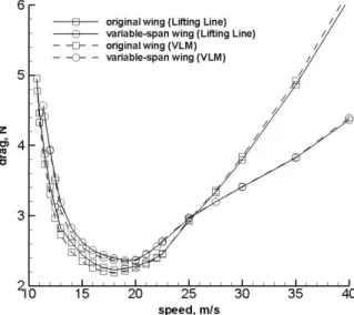
An aerodynamic shape configuration code developed by Gamboa [14] was used to determine a set of optimal wing shapes for reduced drag at a range of flight speeds. The results of this optimization demonstrated (in Fig. 1.5) that the VSW shows better performance (less drag) above 22.5 m/s than a rectangular wing designed with the same stall speed constraint. At 30 m/s, 40 m/s and 50 m/s a total wing drag reduction of 20%, 33% and 40%, respectively, was predicted. At low speeds, the VSW exhibits slightly more drag due to lower efficiency of the modified SG 6042 airfoil adopted.
Figure 1.5 –Drag comparison between original and VSW.
The variations in wing span is not compatible with the use of conventional ailerons, thus, rolling maneuvers must to be controlled by asymmetrical span deployment. It was concluded that the wing showed enough rolling authority, as can be observed in the Fig. 1.6. This system differs from the conventional aileron once it decreases the rolling rate as the velocity increases.
7 The prototype was sized based on the original wing used on the testbed UAV. Therefore, the maximum span was established at 2.5m and, from that, the fixed and movable wing parts were built with 0.625m permitting an overlap of 0.1m in its maximum extended position.
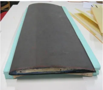
The outer movable wing (OMW) construction was based on a conventional method: balsawood ribs joined by a carbon tubular spar and covered by a carbon skin. As far as the fixed wing is concerned, it had to be hollow so that it could accommodate the movable wing. Consequently, it was made of carbon/epoxy and PVC foam sandwich reinforced with two carbon spar caps. The actuation mechanism was achieved through a modified servo system allowing a maximum deployment of 0.525m, although, it did not demonstrate enough torque to pull the movable wing. The final assembly mass was 1.54kg. Static loading tests carried out revealed an excessive torsion of the wing when loaded with a 9.8N load simulating 3.5g.
Figure 1.7 – VSW mounted on Olharapo’s fuselage [ref].
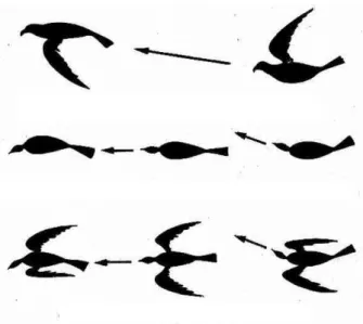
Vale et al [11] designed a telescopic wing that enabled a 15N extra payload and a drag reduction between 1.7 and 12 N in a 100N takeoff weight aircraft. A computational analysis was performed that, apart from altering continuously its wingspan deploying an inner wing through a 750mm distance, also demonstrates airfoil shape change capability, going from a low speed airfoil (Eppler 434) to a high speed airfoil (NACA 0012). Figure 1.8 shows the wing’s structure.
Carbon plates were used to guide the motion of the inner part of the wing which required that this moving part is an open section. The deployment sequence can be observed in Fig. 1.8.
8
Figure 1.8 – Deployment sequence [11, page 4].
A prototype of the wing was built without the airfoil change due to construction limitations at the time. Thus, the NACA 0012 airfoil was adopted with inner and outer wing part chords of 210mm and 280 mm, respectively. The mechanism is actuated by electric motors attached to the inner wing and forcing it to slide along the wing spar and the guide plates in the leading and trailing edges. This method has the disadvantage of presenting open leading and trailing edges.
Ground tests were done to determine the wing’s deployment times and the energy consumed by the actuation system. The results are shown in Table 1.2.
Table 1.2 – Deployment test results [11, page 15].
Taking the results in consideration, it is possible to come to the conclusion that the roll control will not be possible because deployment times are quite large. As far as the energy consumption is concerned, it indicates that a 2200 mAh battery pack could maintain continuous actuation for at least 1.7h.
1.1.4. Inflatable wings
In 2003, Cadogan et al [15] focused his studies in significant advancements concerning deployable inflatable and rigidizable wing structures for UAV and other airship applications. Further developments [16] were based on wing warping to allow roll on inflatable wings. In order to modify the camber section (whose features included high response frequency, low power consumption, high
9 life cycle, among others) the following actuation methods were taken into consideration: piezoelectric actuators, electro-active polymers, shape memory alloys, pneumatic chambers, nastic cells and distributed motor-actuator assemblies.
A system capable of compact packaging for easy transportation and large damage tolerance became the main goal of a later study [7]. The aspect ratio morphing in two different situations was taken into account: one for packed systems which can be dropped or gun launched and deployed wings in flight, and other for a different kind of vehicles requiring aspect ratio changes to improve endurance. Inflatable wing structures show as its major advantage the possibility of close approximation to any wing shape, even those with camber. For low Reynolds numbers (Re < 500,000) a bumpy surface increased aerodynamic performance.
As Shape Memory Alloys (SMA) were promptly accessible and had the required stress and strain response, they corresponded to the most accurate choice for actuation purposes. Flight tests were performed with SMA wires to which a servo mechanism was added. Fast response times with significant wing deflection were accomplished, closer to a wing flap arrangement at the trailing edge. The aeroelastic behavior of the inflatable wing, mainly twisting and bending, was evaluated through wing tunnel testing. The results were within the acceptable values. Through the comparison of a warping wing with traditional ailerons, roll moment coefficient and aileron control power were determined. The gradual deflection was partially responsible for the small over performance of the inflatable wing. Nevertheless, this increase is not observed when concerning the aileron control power. Control tests were executed in order to determine the survivability of a coated fabric wing. These included: rapid deployment, 23 kg sand bag in two different areas of the wing, rapid inflation and flight impact. The absence of any kind of leakage alteration was crucial and confirmed by all tests performed. Thus, inflatable wings showed a high impact survivability, reusability and packability. They also actuated as a kind of airbag, absorbing the impact to other components of the aircraft, ensuring a robust behavior permitting an expanded flight envelope and less proficient piloting.
Inflatable wings were also presented by Jacob et al. A high altitude test [17] exhibited the feasibility of rugged inflatable wings for planetary exploration. The capability of power generation in multifunctional inflatable structures was proved when flexible solar cells were mounted on the wing surface. Aiming at determining the effects of aerodynamic loading and design options for warping actuation, a detailed finite element model of warping Vectran inflatable wings was presented.More recently, discussions have been taking place about the advantages and disadvantages of using this type of wings on UAVs. [18]
In t 2008, Kheong and Jacob [19] approached differently the aspect ratio morphing in flight using inflate wings. The study consisted in an inflatable wing made out of polyurethane fabric with a
10 rectangular form, a 36-inch semi-span from tip to root and a 13.5 inch chord. To each end of a rigid wing, using an NACA 4318 airfoil, an inflatable wing was attached, providing a 150% increase in aspect ratio. In terms of the study itself, two inflatable wings were considered, with and without the folding mechanism. Nevertheless, giving its reduced cost and simpler structural design, the study was focused on the second inflatable wing mentioned. In this case, instead of control surfaces, wing warping was used for roll control.
A flight test was performed taking into account two configurations: a dash one, using the inflatable wings rolled-up to the tips of the rigid wing; and a loiter configuration with the inflatable wing extended. A reduced deployment rate was obtained from the light-weight inflation system which can be positive to decrease the overall aircraft structural weight and strength of the rigid wing due to reduction of dynamic loads (high dynamic loads were experienced on the fuselage skin or rigid wing at high speed deployment) as it unfolds.
Both configurations were submitted to aerodynamic analysis and lift coefficients were predicted. The latter presented a 58% increase after the inflatable wings were deployed. The thrust required calculation displayed a fluctuation of 25% between low and high aspect ratios. A high aspect ratio wing, on the stall speed was beneficial since a reduction from 8.1 m/s to 4.8 m/s was accomplished. Also, some advantages were relevant in the rate of climb, as it was 16% higher when tested at 15.24m/s when compared with the low aspect ratio configuration. Wind tunnel testing revealed the influence of dynamic pressure on the inflatable wing during the inflation process.
1.1.5. Next Generation Morphing Aircraft Structures
Bowman et al [20] presented an overview of the work performed under the program DARPA/AFRL/NextGen Morphing Aircraft Structures (N-MAS). Three important aspects were approached in this overview: motives to morph, technology and systems development to increase the level of technological readiness and future work addressed to the technology progress, challenges concerning technology transition and systems integration.
Regarding the reasons for morphing, some theoretical approaches based on text-book formulas were enough to demonstrate that one must continue to invest in developing morphing technologies. However, in this project, studies and comparisons were made in a wind tunnel with realistic loads to obtain more reliable results. This analysis was based on fuel consumption and not on variables such as turn rate, takeoff distance, etc. After estimating the cost of operating an aircraft equipped with this technology, and cross-referencing the data with the number of sorties, it was concluded that for "hunter-killer" missions morphing technology does makes sense, even with 10% weight untapped,
11 especially for aircraft below 9080N. Another advantage of this technology is to reduce the aircraft fleet.
The requirement to make major changes in geometry of the wing led to the consideration of more than 20 different models, including telescopic wings, joined wings and fan wings. Of all the concepts generated the term "batwing" was chosen based on the following criteria: overall performance, estimated actuation power requirement, perceived ease of construction, feasibility of design, fabrication and testing within the project budget. The design adopted offers large geometry changes, including alterations in aspect ratio of 200%, 40% in span and 70% in wing area. Figure 1.9 illustrates the NextGen concept in different wing settings for five specific flight conditions.
Figure 1.9 - Wing configurations for high-lift, climb, cruise, loiter, and maneuver [20, page 8].
This concept requires some revolutionary wing design tools and analyses as well as unconventional techniques and materials. An example is the skin of the wing that would be flexible enough to allow the change of geometry and which must be of sufficient strength to withstand the aerodynamic loads. Andersen et al [21] developed and tested in the wind tunnel the concept of in-plane moving geometry as well as flexible elastomeric skins. This study analyzed the kinematic-structure with a finite element model and also an aerodynamic consistent model with MSC/NASTRAN™ to assess its aeroelastic behavior.
A model of the batwing concept with the following characteristics: a total weight of 500 kg; wing variable sweep from 15 to 45 degrees, variable wing area from 1.4 m2 to 2.4 m2, and the half-variable span from 2.1 to 3 m, was tested in wind tunnel. These tests had three major objectives: establishing the overall structural integrity of the design by testing it at loads up 2.5g, demonstrating the capability to morph at 1g conditions, and correlating with predictions.
In addition, Flagan et al [22], as a proof-of-concept demonstration, developed and successfully flight tested a 45 kg jet-powered RC (named MFX-1) with the batwing concept. The model flew at altitudes between 122 and 183 m at speeds from 51 to 62 m/s. On this model, the wing area was altered 40 %, the wing span 30 % and the wing sweep varied from 15 to 35 degrees. During the flight, less than 15 seconds were needed in order to achieve a successful morphing cycle.
12
1.1.6. Fully Adaptive Model
The design and construction of a fully adaptive aircraft configuration was managed by Neal et al [23] as an experimenting testbed for aerodynamic modeling and flight control. The aim of the adaptive model design was to achieve several changes concerning shape, so that, morphing for multi-mission UAVs could be explored. These changes were expanded to five independent planform shapes along with the independent twist control for each wing.
The actuation system was composed by two rotational actuators for wing twist and five linear actuators to control wing shape (pneumatic actuators for tail and wing extensions, and a lead-screw mechanism for sweep actuation were used. The control and data acquisition circuit used PC/104 boards and a Matlab/Simulink environment.
The aerodynamic features were evaluated when the 7-DOF experimental model was tested in wind tunnel, with particular attention on the aerodynamic center location and the drag force. It was concluded that, for a span extension of 0%, 50% and 100% the aerodynamic center shifted 19.5%, 22.3% and 25.7%, respectively. The influence of the planform variation was estimated on aircraft stability. It was determined that the CG variation was 11% from an unswept condition to a fully swept one. This indicated that, by increasing the sweep, the aircraft became more stable.
1.2 Objectives
The objectives of this work consisted in the construction and testing an experimental telescopic span wing, actuated by a simple rack and pinion electro-mechanical system, for further application on the UAV Olharapo. Also, the improvement of the 2009’s prototype was taken into account.
The next topics had to be accomplished in order to achieve the goals described:
I. Figure out a solution which improved the sliding between the IFW and OMW. II. Development a system so that the VSW actuates quickly and reliably
III. Study the most applicable construction methods.
IV. Perform bench tests in order to assess the functioning mechanism
1.3 Dissertation layout
The thesis begins with an introduction on morphing concepts and with particular focus on large scale span change studies and experiments. A review on UAV’s equipped with morphing technology is also performed.
13 The dissertation is divided into four main parts: existing VSW prototype evaluation (Chapter 2); design and construction of a new prototype (Chapter 3); VSW evaluation and results (Chapter 4); and a summary (Chapter 5).
Chapter 2 presents the 2009’s prototype issues, as well as the hypotheses and corrective measures. Chapter 3 describes the detailed exposition of the new VSW’s overall construction, including some construction methods evaluation and experiments.
Chapter 4 reports the various tests performed, results and evaluation.
14
Chapter 2
Existing VSW Prototype Evaluation
The VSW prototype implemented by Mestrinho et al [Ref] exhibited some flaws at different levels. Therefore, the first approach to this work was to improve the initial prototype, evaluate its operation and then build the second wing by applying the knowledge gained in the process.
2.1. Issues of 2009’s prototype
At the beginning of this work, the existing prototype presented several problems that required attention:
i. When loaded, the wing showed an excessive torsion (see Fig. 2.1);
ii. The actuation mechanism was not strong enough to make the OMW displacement (Fig. 2.2); iii. The actuation rack was undersized for the actuation force necessary;
iv. The construction method induced some defects in the IFW’s carbon layers (see Fig. 2.3).
a) b)
15
Figure 2.3 – Bubbles and wrinkles on IFW’s surface
2.2.
Hypotheses and corrective measures
2.2.1. Excessive torsion of the wing
The excessive torsion of the wing was due to the lack of stiffness at the trailing edge where the upper and lower skins are joined together. This problem was solved by attaching a triangular profile of balsawood with two layers of carbon/epoxy composite, one on the top side and another on the bottom side, to reinforce the trailing edge thus making the structure into a fully closed section.
2.2.2. Actuation mechanism strength and speed
The actuation servo used in this prototype was a modified ordinary servo that, instead of spinning 2/3 of a turn, or more exactly 210º, would spin sufficient turns to push the OMW through its full extension in time for an effective rolling control. Thus, a compromise between speed and torque was necessary. The servo used was a Futaba S3001 with extra reduction stages added to alter the feedback relation in the potentiometer and the actuation axle repositioned to adjust the number ot turns. These changes have negatively affected the torque that the system could produce. In this specific situation, the torque obtained failed to overcome the friction between the IFW and OMW surfaces.
16 The solution to this problem would be to use more powerful servos and find another way to achieve the necessary displacement.
2.2.3. Rack instability
The new torque values were useful to understand that the rack in use presented excessive torsion when pushed, working in compression, leading to teeth sliding on the pinion.
Having said that, the rack material would have to be changed in a way that it resists buckling and torsion created during the OMW’s outward motion.
2.2.4. Construction defects
The method used to laminate the carbon skins around the PVC foam caused some imperfections which affected the proper sliding to the OMW. In addition, from a structural and aerodynamic point of view, these surface defects are not desirable.
A new construction approach would have to be considered so that all types of friction between the VSW’s moving parts were reduced and structural discontinuities were minimized.
2.3.
Improvements made in 2009’s prototype
The main problems of the 2009’s prototype were the excessive friction between the wing surfaces and exaggerated twist observed in the bending test. Therefore, the main concern was to reduce the sources of friction as much as possible and effectively close the trailing edge. This friction had as main causes the resistance generated between the outer surface of the OMW and the inner surface of the IFW and some imperfections of construction, including ribs with slight differences that altered the thickness of the profile in specific areas of the OMW. To correct the rib’s problem, the carbon skin in these areas was cut and removed. The ribs were trimmed, a small rectangle to cover the cut was laminated. Still, these patches did not comply with the desired perfection.
Some ideas were considered to place ball bearings in the system in order to improve the sliding. From the beginning there were several requirements for this system: it had to have an adjustable slack and easy access to facilitate assembly/disassembly of the wing.
17 A ball bearing rolling device, included in the OMW tubular spar, which slides in an L or T section track would be glued to the inner surface of the IFW, which would illustrate an elegant option. However this system raised several issues on this scale, the bearings could not have more than 3-4 mm in diameter and had to placed within the structure of OMW in an area of difficult access for relaying slacks. Another relevant problem was the fact that OMW needs an opening in the tubular spar to accommodate the track where the ball bearings slide thus converting the tubular spar to a C section beam.
A second option would be to use a system of linear bearings, this system would be mounted on the OMW tubular spar allowing the tube IFW slide within the bearing, permitting a relatively simple implementation. This method was not chosen since most of the IFW's efforts are supported by the shell and not the tube, which serves mostly as a guide. Therefore, the option to include any bearings would require them to pass through the shell of the IFW.
The third option reached the best compromise between simplicity, access, reduction of friction and load transmission. The main objective was to put the OMW sliding inside the IFW without the two surfaces come into contact, or reduce the contact area to a minimum. The system consists of a set of six bearings divided into two groups. A pair of bearings on the trailing edge, keeping a small slack to allow the trailing edge of OMW to slide without touching nothing more than the two bearings. The other two pairs were placed in the IFW’s shell over the center of pressure of OMW, though its position was slightly offset so as not to puncture the stringer of the IFW.
This system was implemented and tested in the original VSW prototype. For this analysis we made some changes, particularly in the structure of OMW and the shell of the IFW. Since loads are transmitted only through the areas of contact between the OMW and the bearing those areas had to be strengthened. In order for a smooth sliding motion to be obtained, the bearings cannot slide directly onto the carbon skin of OMW. Thus, it was necessary to reinforce the OMW carbon skin in the areas of contact with the ball bearings. This strengthening consisted of placing two rectangular tensors made of pultruded carbon on which the bearings slide to ensure sufficient rigidity of the skin of OMW in that particular area.
2.4. Tests
After mounting the bearing system, improvements were evident in the reduction of friction (about 40% improvement) even though, the actuation system developed was not able to perform the deployment on a test bench. The reasons for that were two: the low torque provided by the servo
18 actuator, mainly due to the reduction of gear stages used, and the imperfections on the surfaces in contact.
A second test was carried out where an original servo (without reduction gear) was mounted in the system to evaluate the interaction of all components. The result of this test was not as good as expected. The rack used had not sufficient strength to withstand the forces involved, a new solution remain to be found. Another test was also made to determine the force required for a complete deployment of the OMW. After this test, it was established that a 16. 7N force was needed for a complete deployment without any wing loading.
2.5. Conclusions
After the improvements and tests were performed some conclusions essential to the success of a new prototype were drawn. Starting with the actuation system, a more powerful servo was required to perform a successful deployment and a new system of rack and pinion had do be sized and built. The method of construction and the stiffness of the OMW in the area of contact with the bearings had also have to be improved.
19
Chapter3
Design and Construction of a New VSW Prototype
The concept of the VSW in this project is presented as a hollow fixed wing in which a movable inner wing slides. Dimensions such as wingspan and chord, airfoil, and major structures were maintained from the 2009’s prototype, since the first approach was to improve the original VSW and build the respective pair.
The evaluation of the first VSW’s functionality led to the conclusion that it was crucial to significantly improve the sliding motion between the IFW and OMW. The purpose was to reduce friction so that the actuation mechanism was able to make an effective deployment, even under wing loadings up to 4g. The primary ideas included the insertion of bearings in order to facilitate sliding and improve the method for lamination of fiber layers so that a uniform bonding was guaranteed.
The entire structural design accomplished in the previous work was adopted. In this work, the efforts were centered on validating methods of construction, creating a new actuation system, finishing the construction and testing a pair of the completed and functional wings.
3.1 Preliminary considerations of the manufacturing process
For a suitable lamination and good surface quality, had-layup and vacuum bagging lamination was chosen, since this technique allows a lightweight structure, low cost and reduced complexity. In fact, this procedure allowed drawing much of the resin in excess, prevented air bubbles in the carbon layer and a satisfactory finishing. Briefly, this method consisted in putting the carbon/epoxy in the mold previously protected with wax as releasing agent. Then, a layer of peel-ply was placed, whose function was to provide an ideal finishing for future bonding. Then, the release film was applied and finally a layer of breather. This set was then involved with a film, which after sealed with a vacuum joint, made it air tight. Then, it was just necessary to connect a vacuum pump to the sealed film in order to remove air from the interior.
20
Figure 3.1 – Scheme of the various materials involved in the vacuum lamination.[ http://www.fibertex.com/en-GB/business-areas/Composites/Compoflex/Products/Pages/Products.aspx]
The cure process was performed under controlled temperature conditions, consisting in cure and post-cure. The resin used was SR 1500, which can be used with various hardeners. However, the hardener available was SD 2503, considered a slow one. The manufacturer indicates that the hardener should be used for standard laminations and for all types of applications, having a working times of about 47 minutes at 25 °C. Thus, it appeared to be the suitable hardener for the desired application. Regarding the curing process, the procedure required by the manufacturer, 24 hours at 20 ° C, was performed. After this time, the composite entered in the process of post-cure. There are basically three procedures to perform the post-cure: 14 days at 20 °C, 24 hours at 40 °C or 16 hours at 60 °C. A post cure at 60 °C would be risky because it could damage the various molds used. So, the second procedure was chosen because it was one that combined the best compromise. This procedure was used for all composite fabrications that have been undertaken. In order for the mechanical properties of the composites were known and properly controlled, the performance of the curing process and proper post-curing was extremely important.
3.2 Outer Movable Wing (OMW)
The OMW’s dimensions were maintained so that its wingspan measured 525 mm and a 100 mm overlap when fully extended was obtained, achieving a total of 625 mm for its length.
The need for a smoother, but at the same time more rigid structure in the zone of contact with the bearings, led to some structural changes on the initial OMW. Two stringers of pultruded carbon fiber
21 in the mentioned zone of contact were placed, and later, a 1.5mm balsa web was attached to prevent surface’s deformation, resulting from the force transmitted by the bearings. The set including the stringers and the balsa formed an I-beam, where the stringers were the flanges and the balsa represented the web (see Fig. 3.2). This alteration would substantially increase the bending strength with minimal gain in weight (about 15 grams).
(a) (b)
Figure 3.2 – Construction detail of (a) the balsa web and (b) the carbon flange..
Several construction methods were taken into account, such as autoclave, vacuum bagging and the previous method referred in [14]. Aiming to maintain the reduced weight as well as good fitting between the OMW and the IFW, it was decided to use the vacuum bagging lamination.
Figure 3.3 – Vacuum bagging final installation.
The lamination vacuum was employed in the manufacture of the OMW's shell, and, for this, an external mold was used (Fig. 3.3), made from an internal mold, which would also serve to create the
22 IFW thus providing a fitting in the tolerances between OMW and IFW. In order to avoid extra weight, the stage of lamination of OMW’s skin included already with the upper skin stringer in position.
Figure 3.4 – External mold used to manufacture OMW’s shell.
The ribs were built in 2mm thick balsa wood. Since the OMW’s skin shape depended on the ribs, this step was crucial to obtain a regular surface, providing low resistance in the IFW’s entrance. Thus, a mold was made to allow the manufacture of all ribs at once and with imperceptible differences between them. As noted in the Fig. 3.5, the mould had two lumps in the area where the tubular spar would cross. This feature preserved the ribs integrity and shape during the construction process.
Figure 3.5 – Ribs cutting mold.
Later, the ribs were drilled to accommodate the spar and the rack’s guide tube. The spar consisted of a pultruded carbon tube. Pultruded carbon tubes combine the best compromise between availability,
23 price and specific strength. As for the guide tube, since it is not a structural element, it only had to maintain its integrity and guide the rack of the opposite OMW through the ribs. This tube was built in bidirectional carbon using a PVC pipe as a mold with an outer diameter of 12mm. In the construction process two techniques were tested: (a) the vacuum bagging and (b) by wrapping the carbon around the tube by pressing it with tape to secure the tubular shape. Of the two methods, the second was the one that produced better results since method (a) caused wrinkling in the layers of carbon. The results are shown in Fig. 3.6
Figure 3.6 – Demonstration of the results using technique (a) (right) and (b) (left).
The step of attaching the ribs to the skin was critical, since the slightest imperfection would deform the wing and hinder the entry of the same within the IFW. Therefore, a dock was built (see Fig. 3.7) to ensure the intended shape after collage. As a method of construction, it was chosen a manufacture in expanded polystyrene cut with hot wire. This option was based on the speed of construction combined with the quality of the final result.
(a) (b)
24 At this stage, the balsa plates were added and, in order to increase stiffness, they were placed with the fibers perpendicular to the spar. Later, the lower skin stringer was placed. This set was closed with a flat layer of carbon.
Figure 3.8 – Detail view of the rack supported by OMW’s structure (CAD drawing).
After assembling the final set there was a slight misalignment between racks and guide tubes, which blocked the complete retraction of OMW. In order to reverse the situation, an alignment cone was added in the guide tubes, allowing the rack to follow the desired path. This led to a good retraction.
3.3 Inner fixed wing (IFW)
In this wing, the necessity of obtaining a hollow structure required a structural approach different from the movable wing. So, the whole skin and webless spars of the IFW would not only maintain its shape and resist bending but would also receive the resulting forces transmitted from the OMW when extended.
Taking these restrictions into account, an unusual setting was adopted since the IFW's skin was composed by a sandwich of two layers of carbon with 195 g/m2 and expanded PVC foam in between with a density of 55 kg/m3.
As for the spar, it was composed by two rectangular beams made of pultruded carbon with a cross section of 1.8mm x1.8 mm. For greater rigidity of the set, it was decided to build the spar with the size needed, avoiding unnecessary stress concentrations. These beams had a length of 1600 mm. However, as the dimensions needed were not available, existing only in 1000 × 9 × 0.9 mm, a carbon beam was constructed based on these. Note that these tensors were made of pultruded carbon thus eight of these beams were attached, taking into account the mismatches of all joints in order to minimize the risk of failure. Chamfers were also used in all joints, following the proportion of 1/12.
25 As a support to the bearings, aluminum plates were embedded in the structure thereby effectively distributing the loads transmitted by the set of bearings.
The method of construction adopted was, once again, the vacuum bagging, and in order to build a single skin three phases were necessary. The other option would be to laminate the entire set (carbon/foam/carbon) at once. However, this option was not feasible, given the complexity of interaction between the various impregnated materials. Doing all the steps in one would not make it possible to control the process and ensure the perfection desired. Thus the three phases were (a) to laminate the first carbon layer around the mould, (b) to mark the carbon layer, fold and attach the PVC foam, spars and the aluminum plates to support the bearings in suitable areas, and finally (c) to adjust the discontinuities and laminate the last carbon layer.
a) Phase 1
In the first phase, it was desirable to obtain a surface as smooth as possible so that the OMW’s sliding was improved. Thus, all wrinkles and bubbles between the mold and carbon layer, as well as irregularities on the mold surface were inconvenient.
Since it was necessary to have a small slack between the outer surface of the OMW and the interior of the IFW, at a first approach a 0.1 mm thick plastic film was placed for this purpose. During the process, the loose plastic was not considered very practical, so, for future purposes, an adhesive film should be used in order to confer thickness to the mould, function as release agent. The final result, once only one layer of bidirectional carbon was used, presented gaps in the empty spaces between the fabric fibers. To overcome this problem it would have to be used a very thin layer of fiber (carbon or glass) to cover these gaps. This step was crucial to a successful phase two, because if the glue seeps through the holes in the skin, it would not join the PVC foam effectively.
26
Figure 3.9 – First carbon layer after phase 1.
b) Phase 2
To attach the PVC foam to the carbon layer, tests were performed using epoxy glues of different viscosities (SR 1500 SR 7300 Aerobound with a viscosity of 700 mPa.s and 40000-45000 mPa.s respectively) to obtain the best adhesion from the carbon to the foam. It was concluded after these tests that it would be better to spread the most viscous epoxy glue (aerobound SR 7300) in both the carbon surface and a small, but uniform, layer of glue on the PVC foam. Simultaneously, it presented less maximum resistance, 70 N/mm2 (SR 1500/SD 2503) against 25 N/mm2 (Aerobound SR 7300).
The final properties vary according to the cure process. Taking into account the glue’s features, the SR 1500/SD 2503 was expected to exhibit a more consistent bond though that was not the final result (Fig. 3.10). The reason for this poor outcome was the lower viscosity of the mentioned epoxy glue, allowing the PVC foam to absorb it and its leakage through the first carbon layer.
27
Figure 3.10 – Outcome after the use of epoxy resin SR1500 / SD2503 in the interface carbon-PVC foam.
Once an effective method for bonding was defined, the skin markings were made taking into account the size and positioning of the spars, aluminum plates to support the bearing and PVC foam (see Fig. 3.11).
(a) (b)
Figure 3.11 – Skin during the second phase (a) with marks and aluminum plates in position and (b) skin after conclusion of phase 2.
At this stage, a critical step, already mentioned in Chapter 2, was the of the PVC foam forming compliantly to leading edge. To that end, the foam had to be hot bent. At this point two methods were evaluated: (1) foam heated with hot air and (2) foam heated with hot water. Method (1) showed some imperfections in forming due to a large local heating. Method (2), thanks to the thermal stability of water, managed to maintain a uniform heat distribution across the length of the fold, resulting in a uniform and constant curvature. After folding, the foam was cut into three pieces as needed. The three pieces were attached together followed by the spars and the aluminum plates.
28
Figure 3.12 – Parts of the PVC foam.
c) Phase 3
After gluing the foam onto the first carbon fiber layer, it was necessary to eliminate the discontinuities between this and the spars since their thicknesses differed about 0.2 mm. Therefore, a filler material with a mass of 0.4 g/cm3 was used. To follow up these adjustments, one layer of carbon (240 2) a layer a fiber glass (90
) were laminated on top of the spar to ensure the absence of gaps and a good finish.
(a) (b)
Figure 3.13 – Picture of the skin (a) in the beginning of phase 3 and (b) after application of the filler material. Lower skin portion
Upper skin portion Leading edge portion
29
Figures 3.15 – Picture of the skin after phase 3.
All the results obtained, through the three phases described, showed improvements comparing with a previous experience in which it was possible to notice some problems relating the bonding between the PVC foam and the carbon fiber. This issue was due to excessive resin absorption by the PVC foam and drained glue through gaps in the carbon layer. Since the different layers were not attached properly, the outcome was not resistant enough. Some amends were tried so that the worst imperfections (figure X) would be repaired, though the result was not satisfactory.
30 This was solved by using glue with a higher viscosity and putting a very thin fiber glass in the interior surface of the carbon layer, from what resulted the following sandwich sequence: glass – carbon – PVC foam – carbon – glass.
3.4 Actuation Mechanism
Given that this system was also required to control aircraft rolling, the actuation should occur continuously rather than focusing on a one-time deployment. Thus, during the previous work several actuation options were evaluated, leading to the choice of using a servo motor. This option took into account several factors such as availability, price, weight, simplicity of construction, feasibility and control. In future work, a possible development of an automatic span extension controller should be facilitated by this choice. Another advantage of using the servo motor is the ease of being controlled through a common radio transmitter used in aero modeling. The mechanism consisted of a set rack/pinion actuated by a servo motor.
3.4.1 Set rack/pinion
As stated in Chapter 2, due to torque values needed for proper wing deployment, the material and sizing of the rack had to be revised. Several factors were evaluated, weight, availability, size and price. After searching the market the following options were available: a rack in reinforced plastic (standard), in aluminum (per order) or in steel (standard). As far as the price was concerned, the plastic rack would be the best option, though it does not exist in the market with the desired dimensions. The aluminum rack would have to be ordered, though all budgets asked were quite high.
Figure 3.17 – Generic view of the rack [http://www.chiaravalli.it/home/index_en.htm]
It was decided to purchase a standard rack in steel with the dimensions 15mm x 15mm x 2000mm (b x h0 x L), and a module of 1mm, later to be cut into desired dimensions (5mm x 5mm x 800mm). Since the steel had superior strength relative to aluminum, a section of smaller dimensions could be used, thus approaching the weight of both options (and avoiding a large increase in weight). In Fig. 3.18 the
31 original steel rack with small sections cut from it can be observed. These cuts were made in a cold milling machine.
Figure 3.18 – From right to left: original rack, rack with the desired length and rack with the desired cross section.
As shown in Fig. 3.18, after cutting, the rack suffered significant bending. The stresses produced during cooling of the steel during manufacturing is the possible reason for that behavior. Thus, when cut, the steel tended to bend toward the original exterior face. Noting this fact, the only possibility left was to purchase a rack of aluminum per order. The rack used a section of 9mm x 5mm and a length of 800mm. The main problems observed in the experiment with the prototype in 2009 were (a) buckling of the rack and (b) the pinion sliding through the teeth of the rack. Problem (a) was solved by replacing the balsa rack for an aluminum rack. However, and since this was a critical system for roll control, some buckling calculations were made. Calculations based on reference [27] revealed that a section of 3mm x 3mm was sufficient for an ideal static application. Nevertheless, given that the rack as well as being a critical point of control, acted asymmetrically, it was included in a dynamic system and submitted to vibrations. Adding to the construction issues, a section of 9mm x5mm was chosen. The pinion sliding on the rack (b) has occurred for two reasons. First, the material in which was made of (rubber) has low rigidity and therefore can easily deform allowing the pinion’s teeth to slip. Second, the teeth were too small for the force evolved in actuation. These problems were overcome by changing the material (from rubber to aluminum) and increasing the tooth module to 1 mm.
32
Figure 3.19 – Rack and pinion (left) and rack (right).
3.4.2 Servo motor
In the initial design Futaba S5301 servos were used since they were readily available and had the desired characteristics. In order to increase the servo travel, some modifications and tests were performed, leading to an useless servo. It was essential the equivalence between servos so another model had been considered. When choosing the new servos, several factors had to be considered such as availability, low price, high speed, high torque, low weight and metal gears, being the latter a prerequisite to carry out the necessary modifications. Combining the best compromise, a pair of Hitec HS-805MG servos was purchased.
33
Table 3.1 – Characteristics of HS-805MG servo.
The servo speed, being fast to common use ( ), was not enough for this application. The pinion perimeter was 113.1 mm and 4.6 turns were required (1672.6º), taking 4.2 seconds, to make a complete deployment with a force.
Taking into account the relationship between the 1st and 2nd stages of the servo gears (Fig. 3.21) (gear ratio of 0.385) gave a speed and torque and , respectively. This modification allowed an ideal complete deployment in 1.5 seconds with a force on the rack which was better suited for the application. However, it was necessary to work out a solution to transmit the servo force to the pinion effectively and with little damage to the servo.
Figure 3.21 – Original potentiometer to servo configuration. The red numbers indicate the number of gear’s teeth.
The solution to engage the pinion to the 2nd stage of transmission of the servo was a steel structure, lathe machined, that fit perfectly in the spur gear recess of the 2nd stage. The shaft, 4mm in diameter, is an integral part of the same piece, and is supported by two ball bearings, improving its alignment with the center. In Fig. 3.22 the cut piece as well as the final assembly can be seen.
Motor Type: 3 Pole Ferrite
Current 4,8V 6,0V
Speed (4.8V/6.0V): 316 deg/sec 429
Torque, kg.cm (4.8V/6.0V) 19.8 24.7
Size, mm 65.79 x 29.97 x 57.4
Weight, g 197.03
34
(a) (b) (c)
Figure 3.22 – Servo’s shaft cutting view (a), servo’s shaft (d) and real servo shaft mounted on the gear (c)
To ensure the pinion was well attached to the shaft a plane side was opened on the shaft where a M2 screw makes pressure. Also to resist the torsion moment between the servo and the shaft, two 1.7 mm holes were made inside of which two steel pins were placed to ensure that the shaft would not slip under the actuation forces.
Having done that, attention was turned to increase the servo travel, since the original servo turned only 110º in the 1st stage. A relationship had to be found that converted the 1672.6º in 110o of the potentiometer feedback. This effect required a total reduction ratio of 0.0658 and so, four gears drawn from a set of gears in a S3003 servo were used, with a reduction ratio of 0.45 each. This assembly allowed an overall reduction ratio of 0.0617, which was enough for this application.
35
Figure 3.24 – Detailed views of reduction stages.
3.5 Wing’s central structure
After the actuator system was developed, it was necessary to build a platform capable of supporting the servos and effectively transmitting the forces between them and the VSW, subject to geometric constraints dictated by the fuselage size of the UAV. Considering all this, the result was a plywood board 3 mm thick, supported by two brackets of the same material. These were glued to the wing tube and the spars, as seen in Fig. 3.25. Note that the alignment tube only extended up to the end of the plywood rib unlike the prototype initially proposed. This change was required due to excessive friction between the movable wing tube and the alignment tube.
Figure 3.25 – Central fuselage part: 1) support board, 2) board linkage, 3) wing-fuselage connection and 4) upper board (CAD drawing).
In Fig. 3.25, the upper board (4) supports the pinions’ shafts and the rack’s rollers. The rollers function is to keep the rack in contact with the pinion teeth and restrict their vertical movement. In order to
(1)
(4) (3)
36 reduce friction to an acceptable minimum, ball bearings were placed in all contact zones between shafts and supporting structure.
Figure 3.26 – Rollers and rack detail (CAD drawing).
In order to keep the weight low, these rollers were lathe machined based on a 10 mm aluminum circular rod. In Fig. 3.27, the final result of this structure can be seen.
37
3.6 System mass
After the construction work was complete, all components were weighed in order to evaluate the difference in mass between the conventional wing and telescopic wing. The resin used to impregnate the composite skins is included in several weighed sets. A summary table is presented below with the total mass of the main components. Note that all ball bearings were not considered for the final mass. The wing’s total mass, including the actuation mechanisms, is around 1.85 kg, as opposed to 1.3 kg of the originally wing developed for Olharapo UAV. This amounts to an increase of about 550 g which, is not too exaggerated given the difference in structural and actuation mechanism complexities that exist between the original wing and the telescopic wing.
Part Quantity component weight, g
OMW
20 Balsa ribs 20
2 Carbon tubular spar 108
2 Guide tube 29 2 Skin 142 2 Rack 171 Total OMW 471 IFW 2 Ribs 25 2 Tensors 115 2 Shells + foam 570 Total IFW 852 Actuation bay 1 board 84 2 Modified Servo 400 1 Fuselage linkages 5 4 Board support 8 1 Superior support 9 2 Pinion 90
Total Actuation bay 459
Total mass of VSW 1846
Original Olharapo’s wing mass 1295
38
Chapter 4
VSW Evaluation and Results
A battery of tests was performed in order to evaluate the proper functioning of the system and determine the actual performance of the actuation system developed. Thus, two separate groups of tests were conducted: structural and the system actuator testing.
4.1 Structural Tests
Bending Test:
This test, as the name implies, had as main objective of evaluating the strength and stiffness of the VSW. More specifically, the tip deflection of the wing was measured when it was subjected to different loads representing a range of flight load factors. The flight loads were simulated by placing sandbags on the telescopic wing’s upper skin. For simplicity, the wing load distribution was considered constant in the fixed wing and triangular in the movable wing. Load factors were considered between 0g and 4.5g. Also, all the sand bags were distributed along the main wing spar in order to avoid unnecessary torsion of the telescopic wing assembly. The tip deflection was determined by reading off a scale glued behind the wing tip. Figure 4.1 shows the assembly used to carry out the test.
39
(a) (b)
(c) (d)
Figure 4.2 – Bending test: – (a), – (b), – (c) and – (d).
As can be observed from Fig. 4.2, the increase in load factor led to considerable increase in the wing tip vertical deflection. Also, a slight slope discontinuity was observed at the position where the movable wing enters the fixed wing, particularly at higher load factors. However, the OMW showed to be quite stiff, as it remained completely straight under load. Thus, the overlap of 100 mm between both wing parts resisted the bending loads by deforming the airfoil contour shape: effectively increasing the airfoil thickness. This localized bending was visible from the gap between the IFW upper skin and the OMW upper skin (Fig. X below). This gap became more apparent with higher load factor, reaching a value of about 2 mm under a 4.5g load.
![Figure 1.7 – VSW mounted on Olharapo’s fuselage [ref].](https://thumb-eu.123doks.com/thumbv2/123dok_br/18178842.874297/18.892.276.617.444.746/figure-vsw-mounted-on-olharapo-s-fuselage-ref.webp)
![Figure 1.8 – Deployment sequence [11, page 4].](https://thumb-eu.123doks.com/thumbv2/123dok_br/18178842.874297/19.892.206.691.107.293/figure-deployment-sequence-page.webp)