ABSTRACT: Birds are known for their agility, manoeuvrability, and lexibility during light. These features allow their ability to ly under a large range of light conditions. Bio lyers and bio aerodynamic/luid surfaces have inspired many to perform experiments and simulations as well as to relate their results to engineering applications. Wings speciically have been the most inspirational element. Aerodynamic forces, structure, unsteady low, luid-structure interaction, low control, low adaptive elements and mechanisms, low vortices, lapping mechanisms, and hovering light of birds are examples of research interests. This paper presents an overview of prior analyses and experiments on the aerodynamic performance and mechanical properties of birds in steady non-lapping light.
KEYWORDS: Flexibility, Porosity, Aerodynamics, Birds, Feather.
A Review on Aerodynamics of
Non-Flapping Bird Wings
Mohammed Abdulmalek Aldheeb1, Waqar Asrar1, Erwin Sulaeman1, Ashraf Ali Omar2
INTRODUCTION
Recently, the need for micro air vehicles has resulted in an increase in the attention to bird light and in the study of their performance as they ly at low Reynolds numbers (Carruthers et al. 2010). It is very important to seek the viable aspects in studying natural lyers that can be implemented in practical applications such as wing aerodynamics, structure and control, as noted by Jacob (1998).
Aerodynamics of bird airfoils and wings is classiied into three categories. First, the analysis of airfoils/wings of birds as a ixed rigid body; second, birds airfoils/wings in lapping phase; and third, lexible airfoils/wings in non-lapping light. Bird wing structure is another focus found in some studies in which the feathers bend and twist under aerodynamic forces. herefore, establishing their mechanical properties leads to an understanding of their inluence on aerodynamic performance as studied by Bachmann (2010), Bonser and Purslow (1995), Jacob (1998), Macleod (1980), Purslow and Vincent (1978). Also, movement and vibration of feathers play a role in light control as mentioned by Brown and Fedde (1993) and Jacob (1998), inluencing aerodynamic performance. Adaptive wings improve eiciency, manoeuvrability, control, weight and cost (Jacob 1998).
Natural lyers are diicult to study experimentally due to the complexity in their structural surface, control and agility in manoeuvring (Shyy et al. 2008). he wing structure, surface lexibility, lexibility of feathers, vane and surface hair are a huge challenge to mimic. Another challenge is that the luid motion is unsteady and has many diferent phases as the birds’ lap bend and wings move based on the light conditions. A challenge is that the scaling of both luid dynamics and structural dynamics
1.International Islamic University Malaysia – Kulliyyah of Engineering – Department of Mechanical Engineering – Kuala Lumpur – Malaysia. 2.University of Tripoli – Faculty of Engineering – Department of Aeronautical Engineering – Tripoli – Libya.
Author for correspondence: Waqar Asrar | International Islamic University Malaysia – Kulliyyah of Engineering – Department of Mechanical Engineering | Jalan Gombak, 53100 | Kuala Lumpur – Malaysia | Email: [email protected]
between smaller natural lyer and practical lying hardware/lab experiment (larger dimension) is fundamentally diicult (Shyy et al. 2008). A study of wings with lexible and porous surfaces has not been performed yet. Figure 1 shows a dorsal view of a bird wing planform with its nomenclature that highlights the complex geometry of the multilayer planforms with diferent functionalities for each layer and sublayer components. Figure 2 describes the sublayer component structure that exposes the nature of the non-prismatic, lexible slender beam structure with lexible connections.
MECHANISM/MORPHOLOGY
A feather consists of a shat and vanes (Fig. 3). he inclination of the barbs makes the vane more resistant to aerodynamic forces from its lower side than upper side (Fig. 4). Vanes of a feather are not equally distributed on the shat. One vane is larger than the other side of the feather’s shat, which creates moment on a single feather about its shat. However, multiple feathers overlap resulting in zero moment (a small tilting moment occurs due to the lexibly of the feather) (Muller and Patone 1998).
Mechanical behaviour of wings is afected by diferences in morphology and function of feathers. he outer primaries
are more resistant to forces than inner primaries, especially at the tip, and the outermost primary acts as a reversible airfoil during take-of (Ennos et al. 1995). Tip feathers of a bird’s wing reduce the drag by allowing air to pass thorough and use tip reversal upstroke (Crandell and Tobalske 2011).
Mechanoreceptors — alula receptors, convert feather receptors and secondary feathers receptors — (Fig. 1), associated with feathers, function as low sensors. he discharge frequency of mechanoreceptors is produced by dorsal elevation of coverts, which is related to the elevation of the angle of attack. hey detect low separation point, predict the upcoming low stall point and measure the airspeed on surface using frequency vibration as noted by Brown and Fedde (1993).
Wing alula makes the underwing coverts deployment closed with wing sweep during pitch-up manoeuver and is protected by passive peeling coming off from its tip (Carruthers et al. 2007). he aeroelastic devices were also examined in the Eagle wing using a video camera at a high speed of 500 frames per second placed on the upper wing to analyse the delection of underwing coverts in outdoor and indoor perching sequences. Carruthers et al. (2007) concluded that underwing coverts operate as a high lit device and the alula functions, as strakes.
Figure 1. Topography of a Pigeon wing (dorsal view on a separated Pigeon wing; Bachmann, 2010). The numbers represent location of feathers in the wing.
Greater primary coverts Lesser secondary coverts
Median secondary
coverts Alula
Marginal coverts Alular coverts
Greater secondary
coverts
10th primary covert
10th primary remex
10
9 8 7 6 5
5 6 7 8 9 10
11 4
4
3
3
2 2 1 1
Primary reminges
Secondary reminges Dorsal view
Inner vane Outer vane
25% 50% 75%
Marginals
Dorsal coverts
Remex
Ventral coverts Propatagium
Shaft
Barbs
Barbules
Figure 2. Diagrammatic section of a bird wing at the lower arm level. The shaded area indicates the impervious parts of
the extremity (Muller and Patone 1998). Figure 4. Characteristic of bird feather (Chen et al. 2013).
hese aeroelastic devices seem to be used for low control to enhance unsteady manoeuvres. However, these suggestions are based on visualization of a lying bird and were not determined through experiments.
AERODYNAMICS OF BIO
WINGS/AIRFOILS
Extensive research on airfoil shape, unsteady low analysis, structure and control is required for adaptive wing development where such applications are feasible in practical applications such as micro air vehicles (MAVs) (Jacob 1998).
he drag on bird airfoils is almost constant over a range of lit coeicients, as found by Carruthers et al. (2010), where the aerodynamic performance of reshaped 2-D airfoil of Eagle wing was analysed at Reynolds number of 1 × 10⁵ < Re < 2 × 10⁵.
However, Withers (1981) found that bird wings have high drag coefficient (0.03 – 0.13), which results in low minimum lit-to-drag (L/D) ratio as experimented on a dried bird wing at Re = 1 × 10⁵ – 5 × 10⁵. Bird wings do not perform as good as
conventional airfoils and have low eiciency (Carruthers et al. 2010; Withers 1981). However, this comparison has been made between high Reynolds number airfoils and low Reynolds number bird wing airfoils, which makes this comparison questionable. On the other hand, bird wings have the advantage of performing at a wide range of angles of attack. (Carruthers et al. 2010) used a 2-D airfoil reconstructed from a 3-D scanned wing of a free lying Eagle. However, the 3-D scanning was performed at a single instant of pitching manoeuvre and it represents a single light phase of the bird. Birds have high lit devices that increase the lit at a high angle of attack (Usherwood 2009), and bird wings with low lit coeicients have low drag coeicient and vice versa (Withers 1981).
Barn Owls and Pigeon wings were experimentally studied by Bachmann (2010) who found that Owls have thicker airfoils than Pigeons, which allows Owls to ly at low speed. On the other hand, Pigeons need to beat their wings faster, which leads to a higher speed, but they are noisier compared to Owls (Bachmann 2010). Owl’s feathers absorb the sound that makes them less noisy compared to other birds and they ly almost silently (Chen et al. 2012; Geyer et al. 2014). Pressure distribution on bird’s wing shows that they can be treated using conventional airfoil theory at low Reynolds number as determined by Withers (1981). hin airfoils with Gottingen-like wing camber are more suitable for
MAVs compared to dragon ly wing camber as they produce high L/D ratio, and swept-back leading edge wing increases the performance of MAVs (Lin et al. 2007).
Usherwood (2009) estimated lit coeicients of dried and replica Pigeon wing using direct measurement of forces and mapped forces of pressure distribution. he lit coeicient was found to be 1.64 and 1.44 for dried and replica surfaces, respectively (these values do not represent the actual live bird’s wing as its shape changes based on aerodynamic forces).
Bechert et al. (2000) described techniques of reducing wall shear stress to control boundary layer separation using diferent surface riblets consisting of biological surfaces such as shark skin replica, plastic model scales, hairy surfaces and surfaces where no-slip condition can be controlled.
Chen et al. (2013, 2014) studied the efect of bird wing herringbone riblets on drag and compared them to conventional micro-grooves (riblets). he result shows a drag reduction 16 – 20% higher than in the traditional riblets; moreover, optimal angle between herringbone riblets is about 60°.
he drag on a bird’s body is proportional to its mass; as the mass increases, the drag increases as studied by Pennycuick et al. (1988) on frozen waterfowl bird. he body drag coeicients were estimated to be 0.25 to 0.39 at Re = 145,000 – 462,000. Lit and drag coeicients decrease with increase in light velocity in bound light as experimented by Tobalske et al. (2009) on Zebra Finch. he lit and drag coeicients decrease from 1.19 and 0.95 to 0.7 and 0.54 as the velocity increases from 6 to 10 m/s. he lit coeicient decreases signiicantly as the dihedral angle increases, drag and side forces change signiicantly by the large dihedral angle that leads to change in the rolling and yawing moments and results in unstable changes of aerodynamics parameters as studied by Sachs and Moelyadi (2010).
POROUS WINGS
Porosity is present in bird wings where the low can penetrate between/through feathers. Air transmissivity of feathers was studied by Muller and Patone (1998) from the ventral to dorsal direction and vice versa. It was found that both directions have a small diference in air transmissivity that is about 10%. However, signiicant diference occurs in air transmissivity between inner and outer feather vanes.
of the laps is a function of Reynolds number. However, the properties of lexibility and porosity was not speciied, and the study aimed to analyse drag reduction based on changing Reynolds number and the frequency produced by the flap lexibility regardless of its elasticity value. Yang and Spedding (2013) made 180 small cavities using holes of 0.5 mm diameter on the upper surface of an Eppler 387 wing to use acoustic resonance which changed the aerodynamic performance; the lit coeicients increased from 0.7 to 1, and the drag reduced by 10% at Re = 60,000. At a transitional phase, where Re = 40,000 and the angle of attack ranged from 0 to 9, the L/D ratio was higher compared to the same wing without holes. he improvement in lit coeicient occurs due to the low turbulence inside the hole cavities. However, the study was concerned about resonance efect and not the efect of porosity.
Iosilevskii (2011) analytically studied thin wing membranes segmented into forward solid and aft porous parts. The aerodynamic centre moves non-uniformly to the quarter chord position of the forward section with increase in permeability and leads to a decrease in lit slope. he permeability depends on wing construction and on the light conditions (it increases with velocity). his analytical model needs to be experimentally veriied: an experiment with diferent permeability values, from low to high, and also at diferent Reynolds numbers, would prove this analytical model. he seepage low through the wing reduces the lit slope and creates drag, which can be limited if the at part width is less than the chord length (Iosilevskii 2013). Bae et al. (2012) used CFD to study the efect of porosity on a trailing edge of a 2-D lat plate at Re = 1,000. hey applied numerical penalization method with diferent porosities and predicted the relationship between pressure drop and low velocity compared to numerical low simulation of a non-porous 2-D lat plate. he results showed a reduction in drag and lit due to passive low suction and blowing on the surface. Porosity has a signiicant impact on aerodynamic performance if the proper value of permeability is selected. Study on a 3-D model is yet to be performed, and the criteria for the correct selection of surface porosity are unknown.
FLUID-STRUCTURE INTERACTION
Any change in the structure, such as vibration, deformation or movement due to aerodynamic forces, falls under luid-structure interaction (FSI) analysis. here are two types of FSI: one-way FSI and two-way FSI. One-way FSI changes the luid’s behaviour due to change in structure by controlled
deformation, displacement or vibration. Two-way FSI is deined as changes in the structure because of aerodynamic forces and, then, a change in the aerodynamic behaviour due to the changes in the surface structure caused by the low itself.
Bird wings are lexible, and the airfoil proile changes with aerodynamic forces and light conditions. herefore, the study of FSI is signiicant to understand its impact on light performance (Gursul et al. 2014; Klän et al. 2009; Rojratsirikul et al. 2009).
PASSIVE CONTROL OF FLOW
Elasticity of feathers, wing coverts, surface velvets and feather mechanoreceptors are passive devices for low control and aerodynamic force adjustment to the light conditions as discussed by Brücker and Weidner (2014). he elasticity of the feather shat helps the low to stabilize and allows the bird to control the low during diferent phases of light (Bostandzhiyan et al. 2008).
Velvet-like surfaces on bird wing force the low to reattach and delay the stall for a longer period at high angle of attack (Brücker and Weidner 2014; Klän et al. 2009; Winzen et al. 2013). A signiicant diference is present in the shear-layer roll up process, where it remains almost normal and locked for a longer period in the case of airfoils with adaptive hairy laps while there is a rapid increase in the separation region in clean airfoil (Brücker and Weidner 2014).
compared a set of laps (1 to 4), at diferent positions along the chord and span. Authors claimed that a single lap performs best. Also, downwash force can be reduced by shortening the span of the lap. It was also determined that self-movable laps perform best when they cover 80% of the wing span with width of 0.3 of chord and are located at 0.7 of chord measured from the leading edge. More studies have to be undertaken to obtain an optimum solution.
Another device in bird wings is the leading edge slat (Alula) which acts as a spoiler; it increases lit and stall angle of attack as simulated by Ge et al. (2013) on a 2-D section of a bird wing. However, the leading edge slat in birds (Alula) does not cover all the leading edge but a portion of it. In the mentioned study, natural laps were replaced by artiicial laps to represent high lit systems, enhancing the maximum lit by 20%.
Unsteady flow structure and oscillating airfoil were simultaneously measured and compared to a fixed airfoil by Gursul et al. (2014) and Rojratsirikul et al. (2009). The luctuation of airfoil was investigated as a function of the angle of attack, and it was found that low generates rolling vortices on the top surface in case of a vibrating structure that delays the stall at a higher angle of attack (Rojratsirikul et al. 2009). he lit coeicients for a lexible wing were found to be higher than the coeicients for a rigid wing at sweep angle of 40 – 55°. If the sweep angle is more than 55°, the lit coeicient for a lexible wing becomes less than the coeicient for a rigid wing (Gursul et al. 2014).
he inluence of aerodynamic forces on the large lexibility of a wing was examined experimentally in a wind tunnel using an elasto-lexible wing of a pre-stressed membrane by Béguin and Breitsamter (2014), who found that the aerodynamic forces deform the wing surface and adjust camber based on the aerodynamic conditions when experimented in a large lexible wing. However, the question that remains unanswered is the modulus of elasticity selection criteria or the range/criteria of the aeroelastic non-dimensional parameter. Numerical simulations on segmented airfoil show an increase in the lit of up to 39% near the stall angle (Hefeng et al. 2015). hree-segmented lexible airfoils produce better results than other segmented conigurations. However, further studies on segmented airfoils are needed to ind out if equal segments on airfoil surface result in optimal performance or not. Furthermore, experimental data could lead to validated simulation results.
he ability of a low to vibrate lexible membranes was tested by Genç (2013) on 2-D and 3-D low aspect ratio wings;
2-D membrane wings vibrate more than 3-D wings because of the absence of tip vortex in 2-D wings that allows the shear layer to get closer to the surface. he largest deformation of the lexible membrane occurs near the tip due to the tip vortices. Flexible surfaces perform aerodynamically better than rigid surfaces; they delay the separation at a high angle of attack and can be used as passive control (Du and Sun 2010; Genç 2013; Gursul et al. 2014; Hefeng et al. 2015; Rojratsirikul et al. 2009).
BIRD WING TIP/WINGLET
Winglets are devices to reduce the induced drag, and, in birds, they are lexible. Wing tip feathers of birds are considered to be winglets and they are lexible with spiral multi-feather elements. Bird wings are considered as non-planar, and a basic theory of non-planar systems is given by Cone Jr (1962) to determine the minimum induced drag and lit that can be expressed regarding aspect ratio and vortices distribution. A spiroid winglet was introduced by Guerrero et al. (2012) and was found to increase the lit and its slope by 9% .he L/D ratio improved by approximately 7%. However, it increased the parasite drag due to increase in surface area as well as interference drag. On the other hand, the spiroid winglet used by Guerrero et al. (2012) does not represent the bird winglet in terms of shape and lexibility.
Eder et al. (2015) estimated the induced drag factor of free-lying White Storks by calculating bird speed versus wing loading and aspect ratio. he induced drag factor ranges from 0.7 to 0.96 at lit coeicients of 1.2 – 1.6.
Tucker (1993) compared three types of wingtips: feathers of Harris’ Hawk, slotted tip made of balsa wood and shaped as Clark Y airfoils and unslotted Clark Y wingtip mounted on a base wing. Feathers on the tip of bird wings reduce the drag ratio by 105% as the angle of attack increases from 4° to 14°. On the other hand, the L/D ratio of slotted balsa wing tips increased by 49% whereas the L/D ratio of unslotted Clark Y increased by 5% only. As the angle of attack increases from 0° to 15°, the drag increased by 25% in unslotted Clark Y and decreased by 6% in wing with feathers tip. he total drag of wing with feathers decreased by 12% compared to other wings. However, the bird feathers are lexible and bend at airspeed — these afect even the shape of the feather. Flexibility and shape of the wing tip feather under aerodynamic forces cause diference in L/D ratio and drag reduction.
them to the same wing tip but with clipping of the feather tip. he tests were performed in a wind tunnel for a free gliding Hawk at speeds from 7.3 to 15 m/s. he induced drag factor of unclipped feathers is about 0.56 and increased to 1.1 in clipped feathers. hus, it has been veriied that bird wing tip feathers cause a reduction in drag.
was done using active control, it shows the efect of surface shape on aerodynamic performance, which is similar to the case of
birds, since their wing surfaces are lexible and can be morphed
to accommodate the varying light conditions during diferent light phases, producing maximum aerodynamic performance.
AERODYNAMICS OF GLIDING FLIGHT
Gliding is lying without lapping the wings, and birds use gliding mode to save energy (Videler and Groenewold 1991). Birds adjust their wing span in gliding to have enough lit and ly at a certain glide angle to keep them alot (Tucker and Parrott 1970; Zahedi and Khan 2007). Gliding is described as the relationship between bird wing speed and airspeed. here are two types of gliding: static, in which birds depend on the upward wind velocity, and dynamic, where the birds use the changing axial airspeed to stay alot (Tucker and Parrott 1970). Zahedi and Khan (2007) studied theoretically the wing taper factors for birds. he model was developed from three birds (Jackdaw, Harris’ Hawk and Laggar Falcon) to estimate the taper factor of their wings which are 1.8, 1.5 and 1.8, respectively. Also, an equation was derived to estimate the minimum wing span ratio during glide light. Tucker (1987) analytically studied the efect of variable wing span on gliding and deined the gliding maximum performance curve as the minimum sinking speed at each air speed.
Experiments on bird glide show that L/D ratio of Pigeon in gliding is 10, and the maximum vertical diving speed of Laggar Falcon is 100 m/s. Tucker and Parrott (1970) used a trained Pigeon in a wind tunnel to glide at different speeds, investigating the gliding performance in a more accurate sense. However, the L/D ratio of Kestrel gliding is 10.9 at a speed of 14.9 m/s, and the angle of attack is 5.5° (Videler and Groenewold 1991). Extended wings are great for both gliding and turning. Swept wings are better for fast glide but less active in generating lift while turning at high speeds, sink speed and turning rate are hugely affected by selecting the right sweep (Lentink et al. 2007).
Field experiments by Videler and Groenewold (1991) suggest that birds use three methods to adjust lit and drag in gliding: wing span variation, pitching angle of bird’s longitudinal axis (which is independent from wind speed) and spreading the tail to adjust the lit and drag. Bird tail has efect on L/D ratio; if the tail is trimmed, it reduces the L/D ratio and, if extended, it increases the L/D ratio (Tobalske et al. 2009). However, in wind tunnel, the birds only use wing span to control lit and 10
10
9 9
5
5 6 6
7
78 8
Figure 5. Tip of Harris’ Hawk in light (Tucker 1995).
ACTIVE CONTROL
drag (Tucker 1987). Glide angle increases with the increase in dihedral angle of bird wing (Sachs and Moelyadi 2010).
STRUCTURE
An understanding of the mechanical properties of feathers is essential as they directly afect the aerodynamic properties due to their elasticity. A general review of feather on bird’s feather biomechanics and structure was done by Zahedi and Khan (2007). he structure and shape of rachis allow them to withstand high forces and prevent them from cracking. Studies on feather microstructure show that the iber matrix of keratin is arranged in such a way that it provides stifness and strength;
at the same time, it is lexible and elastic.
Bonser and Purslow (1995) examined the properties of feather keratin to ind the Young’s modulus (E) through tensile tests for eight diferent bird feathers. Modulus of elasticity for feathers was E = 2.5 GPa for all birds except for Grey Heron — E = 1.78 GPa. However, Purslow and Vincent (1978) found an E for the feather shat of Pigeon equal to 7.8 ± 2% GPa. Bachmann et al. (2012) found the Young’s modulus values of Pigeon and Barn Owl feathers between 4.14 and 6.93 GPa. On the other hand, Macleod (1980) examined the Young’s modulus of contour feather for Brown Chicken, Turkey, Pheasant and Herring Gull in tension and bending tests and for distal and proximal regions. he results from the tension tests show that E ranges from 0.045 to 0.181 GPa and from 0.21 to 0.682 GPa for proximal and distal regions, respectively. In bending tests, E ranges from 0.005 to 0.024 GPa and from 0.457 to 1.85 GPa for proximal and distal regions, respectively. here is a diference in range of magnitude for the stifness values due to diferent methods or tests used (Bonser and Purslow 1995). Rachis cross-section geometry controls the lexural stifness rather than keratin material properties according to Bachmann et al. (2012), Bonser and Purslow (1995) as well as Purslow and Vincent (1978). he geometry and the second moment of area of the feather shat increase as the body weight increases and vice versa. Second moment of area gradually decreases along the shat from feather base to its tip, which results in higher rigidity in feather shat at its root and greater elasticity at the tip (Bostandzhiyan et al. 2008; Macleod 1980; Purslow and Vincent 1978).
Bird wings can withstand higher forces than the forces they are normally exposed to. Normal stress applied on birds
feather is 8.3 up to 15.7 MPa while the ultimate stress point at the bending is 137 MPa, which gives a safety factor between 6 and 12 (Corning and Biewener 1998). his feature of safety allows them to ly under extreme conditions. Flexural stifness is more critical than strength in feather shat.
However, all the studies mentioned above focused on the feather structure properties, especially feather shat properties, which gives strength for the bird wing to withstand the forces. Investigation of the elasticity modulus of the coverts (hairs) is still required. he coverts pop-up when birds ly at a high angle of attack. To make a lexible surface similar to a bird’s surface or to study the efect of coverts on aerodynamic performance, the properties of the coverts need to be known.
EXPERIMENTS/SIMULATION METHODS
In Aerodynamics, there are three ways of predicting or calculating the aerodynamic performance of wings/airfoil, which are: analytical/mathematical model, numerical simulation and experimental test. Analytical/mathematical model is used to represent a speciic problem, but in general it is derived for simple geometries/airfoils. Numerical simulation is widely used to solve complicated problems as it reduces the cost of experiments, although it is costly in terms of time. Experimental test is considered the most robust method if done correctly, because it gives more realistic results. It is also used to verify the results of simulations.
One of the experimental methods is the particle image velocimetry (PIV), which has been used to measure the inluence of hairy surfaces on aerodynamic performance and separation control by Brücker and Weidner (2014), Klän et al. (2009) and Winzen et al. (2013). Pressure distribution measurements and oil pattern method were used by Klän et al. (2009) to verify the results obtained from PIV, and the results show agreement among the three methods. In their experiments, the airfoil proile used was obtained form an average reconstructed artiicial wing obtained by scanning an Owl’s wing. Rojratsirikul et al. (2009) used high speed PIV to study the luid structure interaction of a 2-D airfoil at a Reynolds number range of 53,100 – 106,000. he measurements were taken for the unsteady low and structural changes simultaneously, and the oscillation in structure behaviour was investigated as a function of angle of attack and velocity.
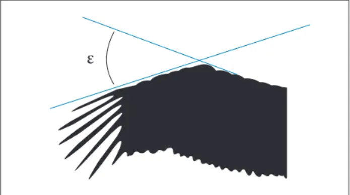
Figure 6. The wrist angle (ε) between the frontal edge of the
cascade and the propatagium sinew (Eder et al. 2015).
ε
he measurements were performed at diferent speeds from 2 to 12 m/s and diferent angles of attack ranging from −5° to 50°. A uniform structure of the wake was observed, and the forces derived from both measurements of PIV and force transducer have a close agreement.
he dual-plane PIV has been used by Waldman and Breuer (2012) to increase the dynamic range of PIV measurements on a ixed wing and has been compared to PIV. Both measurements indicate the same position of vortex downstream but dual-plane PIV covers a more dynamic range by an order of magnitude. Dual-plane PIV captures the velocity of outer flow more accurately, which leads to more accurate results. It is also able to capture the strength of the wake downstream qualitatively and quantitatively.
Another development of PIV, called digital PIV (DPIV),
has been used by Spedding et al. (2003) in low-turbulence wind
tunnel to study the free-lying bird wake. DPIV measurement
uses two cameras and allows a moving object to wake so that it can be measured more accurately and with more reliability. he shortcoming of the method is the diiculty in matching the optical axis of the two cameras. However, mismatches can be removed to quite high accuracy, by careful mapping of the apparent displacements of stationary control objects imaged by both cameras. It removes the disturbances of lens/camera and examines only the efect of moving object disturbances. Spedding et al. (2009) conirmed the ability of DPIV to measure the background structure of small turbulences in a low turbulence wind tunnel, which can be used to measure the aerodynamics of small lyers. Genç (2013) also used DPIV in a closed loop open-jet wind tunnel to calculate the average and instantaneous velocity ield on a membrane wing at Re = 48,700. hey also used digital image correlation system to measure membrane deformation and load cell, calculating forces on the wing. Waldman and Breuer (2012) used a ixed model with load cell direct measurement of aerodynamic forces to explore the challenges of selecting appropriate experimental parameters to have more accurate dynamic measurements. Isaac et al. (2006) used hydrogen bubbles and dyes as traces to visualize the low over a moving and pitching lat blade.
Visualization of low on lying birds is another method for examining the light mechanism or low separations. Carruthers et al. (2007) used a high-speed camera carried by an Eagle to examine the function of coverts in perching modes. Eder et al. (2015) performed ield measurements using infrared laser tracking to estimate the induced drag of souring and gliding
light of White Storks. he test was carried for 100 adult White Storks and it was found that the speed ranges of these birds at soaring, gliding and fast speed are 7.5 – 10, 10 – 14 and 14 – 19 m/s, respectively. he wrist angle (angle between the frontal edge of the cascade and the propatagium sinew — see Fig. 6) ranges of soaring, gliding and fast light are 15° – 19°, 20° – 24° and 25° – 50°, respectively.
Chen et al. (2013, 2014) used SEM and CFD to investigate the efects of herringbone-type riblets on drag reduction using a microstructure of secondary feathers of Pigeon and then used a 3-D plane with herringbone riblets to compare them to traditional riblets.
Sachs and Moelyadi (2010) used CFD to study the efect of large dihedral angle of Pigeon-like wings on aerodynamic performance. A CAD model for Pigeon wing at different dihedral angles was used. he airfoil section is the same for all dihedral angles. However, the shape of airfoil in real birds changes during each light phase; thus, this simulation is simpliied to a minimum complexity of bird wing geometry. On the other hand, analytical aerodynamic analysis of lexible and bird-like wing/airfoils was attempted by Iosilevskii (2013), who derived a closed-form mathematical model for the lit and pitching-moment coeicients of a thin wing membrane by sectioning the surface into two parts: a solid forward part that is impermeable and the at part, which is porous. Another closed-form solution is obtained to study the seepage drag for the same model using Darcy’s law. Venkataraman et al. (2014) developed a linear mathematical model by combining vortex-shedding minimal-order model with oscillator mode to study FSI and its efects on the low region. Both minimal model proelastic coating and FSI coupling are assumed to be linear.
shape and properties in mathematical, simulation or experimental
form. Mazellier et al. (2012) implemented a biomimetic approach
and used a squared cylinder geometry with free-rotating elastic self-deformable (made of a rigid material coated with plastic
skeleton) porous (fabric) laps to replicate the feather vane to
study its efects on aerodynamic performance. Lin et al. (2007) developed aluminum plates with Gottingen wing — a wing span of 15 cm, thickness to chord ratio of 1.3 and camber of 6% — and compared their aerodynamic performance to other airfoils that have a half-forward part similar to a dragonly wing. Corning and Biewener (1998) used a metal foil strain gauge to evaluate the safety factor in feather shat of a free-lying Pigeon. Strain was recorded at both compression (down stroke) and tension (up stroke). Photogrammetric reconstruction technique was used by Carruthers et al. (2010) to reconstruct the wing section of a free-lying Eagle. A mathematical model was used to reshape 2-D airfoil, analyzing the aerodynamic performance. Klän et al. (2009) also used Owl airfoil extracted from a 3-D scanned wing and experimented it in a wind tunnel at Re = 2,000 – 4,000 with and without velvet to study the efect of velvet on delaying stall angle. However, the 3-D shape was smoothed and the twist was removed. he efect of smoothing Owl wing and removing the twist might have signiicant impact on aerodynamic performances.
he aerodynamic performance of real birds was studied by Pennycuick et al. (1988), who used a frozen waterfowl in a wind tunnel to estimate the drag coefficient at Reynolds
number of 145,000 - 462,000, and Usherwood (2009), who used a dried Pigeon wing and a replica lat plate to measure and compare aerodynamic forces on both revolving surfaces at a Reynolds number of 108,000 using a propeller rig. he direct measurement of forces was taken, and the mapped forces of pressure distribution were calculated. Withers (1981) also used dried wings of diferent types of birds and experimented them at Re = 1 – 5 × 10⁵. Dried wings, however, difer from live
bird wings, which might afect the aerodynamic performance. MAVs, wind turbines, tidal wave turbines and other devices perform at low Reynolds numbers similar to birds. hus, lessons learnt from aerodynamics of bird wings in steady light could be implemented in such applications to enhance their performance.
CONCLUSION
his paper focuses on the past research carried out on ixed bird wings (non-lapping wing), in terms of analysis, simulation and experiments which have been performed by researches for a wide range of bird wing aerodynamics. However, some areas in bird aerodynamics can be studied more thoroughly as the bird wings consist of highly complex representation of lexible (not lapping) and porous surfaces. Many of these problems are mentioned throughout this article.
REFERENCES
Bachmann T (2010) Anatomical, morphometrical and biomechanical studies of barn owls’ and pigeons’ wings (Master’s thesis). Aachen: RWTH Aachen University.
Bachmann T, Emmerlich J, Baumgartner W, Schneider JM, Wagner H (2012) Flexural stiffness of feather shafts: geometry rules over material properties. J Exp Biol 215(Pt 3):405-415. doi: 10.1242/ jeb.059451
Bae Y, Jeong YE, Moon YJ (2012) Computation of low past a lat plate with porous trailing edge using a penalization method. Comput Fluid 66:39-51. doi: 10.1016/j.compluid.2012.06.002
Bechert D, Bruse M, Hage W, Meyer R (2000) Fluid mechanics of biological surfaces and their technological application. Naturwissenschaften 87(4):157-171.
Béguin B, Breitsamter C (2014) Effects of membrane pre-stress on the aerodynamic characteristics of an elasto-lexible morphing wing. Aero Sci Tech 37:138-150. doi: 10.1016/j.ast.2014.05.005
Bilgen O, Friswell MI, Kochersberger KB, Inman DJ (2011) Surface actuated variable-camber and variable-twist morphing wings using piezocomposites. Proceedings of the 52nd AIAA/ASME/ASCE/
AHS/ASC Structures, Structural Dynamics, and Materials 4(7):2011-2072. doi: 10.2514/6.2011-2072
Bilgen O, Kochersberger KB, Inman DJ, Ohanian OJ (2010) Novel, bidirectional, variable-camber airfoil via macro-iber composite actuators. J Aircraft 47(1):303-314.
Bonser R, Purslow P (1995) The Young’s modulus of feather keratin. J Exp Biol 198(4):1029-1033.
Bostandzhiyan S, Bokov A, Shteinberg A (2008) Flexural characteristics and aerodynamic aspects of the design of the bird feather shaft. Doklady Physics 53(9):476-479. doi: 10.1134/S1028335808090036
Brown RE, Fedde MR (1993) Airlow sensors in the avian wing. J Exp Biol 179(1):13-30.
Brücker C, Weidner C (2014) Inluence of self-adaptive hairy laps on the stall delay of an airfoil in ramp-up motion. J Fluid Struct 47:31-40. doi: 10.1016/j.jluidstructs.2014.02.014
Carruthers A, Walker S, Thomas A, Taylor G (2010) Aerodynamics of aerofoil sections measured on a free-lying bird. Proc IME G J Aero Eng 224(8):855-864. doi: 10.1243/09544100JAERO737
Chen H, Rao F, Shang X, Zhang D, Hagiwara I (2013) Biomimetic drag reduction study on herringbone riblets of bird feather. J Bionic Eng 10(3):341-349. doi: 10.1016/S1672-6529(13)60229-2
Chen H, Rao F, Shang X, Zhang D, Hagiwara I (2014) Flow over bio-inspired 3D herringbone wall riblets. Exp Fluids 55:1698. doi: 10.1007/s00348-014-1698-4
Chen K, Liu Q, Liao G, Yang Y, Ren L, Yang H, Chen X (2012) The sound suppression characteristics of wing feather of owl (Bubo bubo). J Bionic
Eng 9(2):192-199. doi: 10.1016/S1672-6529(11)60109-1
Cone Jr CD (1962) The theory of induced lift and minimum induced drag of nonplanar lifting systems. NASA TR R-139.
Corning WR, Biewener AA (1998) In vivo strains in Pigeon light feather
shafts: implications for structural design. J Exp Biol 201(Pt 22):3057-3065.
Crandell KE, Tobalske BW (2011) Aerodynamics of tip-reversal upstroke in a revolving Pigeon wing. J Exp Biol 214(11):1867-1873. doi: 10.1242/jeb.051342
Du G, Sun M (2010) Effects of wing deformation on aerodynamic forces in hovering hoverlies. J Exp Biol 213(Pt 13):2273-2283. doi: 10.1242/jeb.040295
Eder H, Fiedler W, Neuhäuser M (2015) Evaluation of aerodynamic parameters from infrared laser tracking of free-gliding white storks. Journal of Ornithology 156(3):1-11. doi: 10.1007/s10336-015-1176-7
Ennos A, Hickson J, Roberts A (1995) Functional morphology of the vanes of the light feathers of the Pigeon Columba livia. J Exp Biol 198(5):1219-1228.
Ge C, Ren L, Liang P, Zhang C, Zhang Z (2013) High-lift effect of bionic slat based on owl wing. J Bionic Eng 10(4):456-463. doi: 10.1016/ S1672-6529(13)60243-7
Genç MS (2013) Unsteady aerodynamics and low-induced vibrations of a low aspect ratio rectangular membrane wing with excess length. Exp Therm Fluid Sci 44:749-759. doi: 10.1016/ j.expthermlusci.2012.09.018
Geyer T, Sarradj E, Fritzsche C (2014) Measuring owl light noise. Proceedings of the Inter-Noise Congress and Conference; Melbourne, Australia.
Guerrero JE, Maestro D, Bottaro A (2012) Biomimetic spiroid winglets for lift and drag control. C R Mec 340(1-2):67-80. doi: 10.1016/ j.crme.2011.11.007
Gursul I, Cleaver D, Wang Z (2014) Control of low Reynolds number lows by means of luid-structure interactions. Progr Aero Sci 64:17-55. doi: 10.1016/j.paerosci.2013.07.004
Hefeng D, Chenxi W, Shaobin L, Zhen SX (2015) Numerical research on segmented lexible airfoils considering luid-structure interaction. Procedia Eng 99:57-66. doi: 10.1016/j.proeng.2014.12.508
Iosilevskii G (2011) Aerodynamics of permeable membrane wings. Eur J Mech B Fluids 30(5):534-542. doi: 10.1016/ j.euromechlu.2011.05.003
Iosilevskii G (2013) Aerodynamics of permeable membrane wings. Part 2: Seepage drag. Eur J Mech B Fluids 39:32-41. doi: 10.1016/ j.euromechlu.2012.11.004
Isaac KM, Rolwes J, Colozza A (2006) Unsteady low features of a lapping and pitching wing at low Reynolds number. AIAA Paper3145.
Jacob J (1998) On the luid dynamics of adaptive airfoils. American Society of Mechanical Engineers, Aerospace Division 57:167-176.
Klän S, Bachmann T, Klaas M, Wagner H, Schröder W (2009) Experimental analysis of the low ield over a novel owl based airfoil. Exp Fluids 46(5):975-989. doi: 10.1007/s00348-008-0600-7
Lentink D, Müller U, Stamhuis E, De Kat R, Van Gestel W, Veldhuis L, Henningsson P, Hedenström A, Videler JJ, Van Leeuwen JL (2007) How swifts control their glide performance with morphing wings. Nature 446(7139):1082-1085. doi: 10.1038/nature05733
Lin J, Wei C, Lin C (2007) Aerodynamic performance of thin wings at low Reynolds numbers. Aircr Eng Aerosp Tech 79(3):245-253. doi: 10.1108/00022660710743840
Macleod GD (1980) Mechanical properties of contour feathers. J Exp Biol 87(1):65-71.
Mazellier N, Feuvrier A, Kourta A (2012) Biomimetic bluff body drag reduction by self-adaptive porous laps. C R Mec 340(1-2):81-94. doi: 10.1016/j.crme.2011.11.006
Muller W, Patone G (1998) Air transmissivity of feathers. J Exp Biol 201(Pt 18):2591-2599.
Pennycuick C, Obrecht HH, Fuller MR (1988) Empirical estimates of body drag of large waterfowl and raptors. J Exp Biol 135(1):253-264.
Pinkerton JL, Moses RW (1997) A feasibility study to control airfoil shape using THUNDER. NASA technical memorandum; 4767. Washington: National Aeronautics and Space Administration.
Purslow P, Vincent J (1978) Mechanical properties of primary feathers from the Pigeon. J Exp Biol 72(1):251-260.
Rojratsirikul P, Wang Z, Gursul I (2009) Unsteady luid-structure interactions of membrane airfoils at low Reynolds numbers. Exp Fluids 46:859. doi: 10.1007/s00348-009-0623-8
Sachs G, Moelyadi MA (2010) CFD based determination of aerodynamic effects on birds with extremely large dihedral. J Bionic Eng 7(1):95-101. doi: 10.1016/S1672-6529(09)60191-8
Schatz M, Bunge U, Lübcke H, Thiele F (2001) Numerical study of separation control by movable laps. In: Thiede P, editor. Aerodynamic Drag Reduction Technologies. Berlin: Springer. p. 385-390.
Schluter JU (2010) Lift enhancement at low Reynolds numbers using self-activated movable laps. J Aircraft 47(1):348-351. doi: 10.2514/1.46425
Shyy W, Lian Y, Tang J, Liu H, Trizila P, Stanford B, Bernal L, Cesnik C, Friedmann P, Ifju P (2008) Computational aerodynamics of low Reynolds number plunging, pitching and lexible wings for MAV applications. Acta Mechanica Sinica 24(4):351-373. doi: 10.1007/s10409-008-0164-z
Spedding G, Hedenström A, Johansson L (2009) A note on wind-tunnel turbulence measurements with DPIV. Exp Fluids 46(3):527-537. doi: 10.1007/s00348-008-0578-1
Spedding G, Hedenström A, Rosén M (2003) Quantitative studies of the wakes of freely lying birds in a low-turbulence wind tunnel. Exp Fluids 34(2):291-303. doi: 10.1007/s00348-002-0559-8
Tucker VA (1987) Gliding birds: the effect of variable wing span. J Exp Biol 133(1):33-58.
Tucker VA (1993) Gliding birds: reduction of induced drag by wing tip slots between the primary feathers. J Exp Biol 180(1):285-310.
Tucker VA (1995) Drag reduction by wing tip slots in a gliding Harris’ Hawk, Parabuteo unicinctus. J Exp Biol 198(Pt 3):775-781.
Tucker VA, Parrott GC (1970) Aerodynamics of gliding light in a Falcon and other birds.J Exp Biol 52(2):345-367.
Usherwood JR (2009) The aerodynamic forces and pressure distribution of a revolving Pigeon wing. Exp Fluids 46(5):991-1003. doi: 10.1007/s00348-008-0596-z
Venkataraman D, Bottaro A, Govindarajan R (2014) A minimal model for low control on an aerofoil using a poro-elastic coating. J Fluid Struct 47:150-164. doi: 10.1016/j.jluidstructs.2014.02.012
Videler J, Groenewold A (1991) Field measurements of hanging light aerodynamics in the kestrel Falco tinnunculus. J Exp Biol 155(1):519-530.
Waldman RM, Breuer KS (2012) Accurate measurement of streamwise vortices using dual-plane PIV. Exp Fluids 53(5):1487-1500. doi: 10.1007/s00348-012-1368-3
Wang CJ, Schlüter J (2012) Stall control with feathers: Self-activated laps on inite wings at low Reynolds numbers. C R Mec 340(1-2):57-66. doi: 10.1016/j.crme.2011.11.001
Winzen A, Klaas M, Schröder W (2013) High-speed PIV measurements of the near-wall low ield over hairy surfaces. Exp Fluids 54:1472. doi: 10.1007/s00348-013-1472-z
Withers PC (1981) An aerodynamic analysis of bird wings as ixed aerofoils. J Exp Biol 90(1):143-162.
Yang S, Spedding G (2013) Passive separation control by acoustic resonance. Exp Fluids 54:1603. doi: 10.1007/s00348-013-1603-6