HESSD
9, 1515–1546, 2012Simulation of saturated and unsaturated flow in
karst systems
J. Kordilla et al.
Title Page
Abstract Introduction
Conclusions References
Tables Figures
◭ ◮
◭ ◮
Back Close
Full Screen / Esc
Printer-friendly Version Interactive Discussion
Discussion
P
a
per
|
Dis
cussion
P
a
per
|
Discussion
P
a
per
|
Discussio
n
P
a
per
|
Hydrol. Earth Syst. Sci. Discuss., 9, 1515–1546, 2012 www.hydrol-earth-syst-sci-discuss.net/9/1515/2012/ doi:10.5194/hessd-9-1515-2012
© Author(s) 2012. CC Attribution 3.0 License.
Hydrology and Earth System Sciences Discussions
This discussion paper is/has been under review for the journal Hydrology and Earth System Sciences (HESS). Please refer to the corresponding final paper in HESS if available.
Simulation of saturated and unsaturated
flow in karst systems at catchment scale
using a double continuum approach
J. Kordilla1, M. Sauter1, T. Reimann2, and T. Geyer1
1
Geoscientific Centre, University of G ¨ottingen, G ¨ottingen, Germany
2
Institute for Groundwater Management, TU Dresden, Dresden, Germany
Received: 16 January 2012 – Accepted: 23 January 2012 – Published: 1 February 2012
Correspondence to: J. Kordilla ([email protected])
HESSD
9, 1515–1546, 2012Simulation of saturated and unsaturated flow in
karst systems
J. Kordilla et al.
Title Page
Abstract Introduction
Conclusions References
Tables Figures
◭ ◮
◭ ◮
Back Close
Full Screen / Esc
Printer-friendly Version Interactive Discussion
Discussion
P
a
per
|
Dis
cussion
P
a
per
|
Discussion
P
a
per
|
Discussio
n
P
a
per
|
Abstract
The objective of this work is the simulation of saturated and unsaturated flow in a karsti-fied aquifer using a double continuum approach. The HydroGeoSphere code (Therrien et al., 2006) is employed to simulate spring discharge with the Richards equations and van Genuchten parameters to represent flow in the (1) fractured matrix and (2) conduit
5
continuum coupled by a linear exchange term. Rapid vertical small-scale flow pro-cesses in the unsaturated conduit continuum are accounted for by applying recharge boundary conditions at the bottom of the saturated model domain. An extensive sen-sitivity analysis is performed on single parameters as well as parameter combinations. The transient hydraulic response of the karst spring is strongly controlled by the matrix
10
porosity as well as the van Genuchten parameters of the unsaturated matrix, which determine the head dependent inter-continuum water transfer when the conduits are draining the matrix. Sensitivities of parameter combinations partially reveal a non-linear dependence over the parameter space. This can be observed for parameters not be-longing to the same continuum as well as combinations, which involve the exchange
15
parameter, showing that results of the double continuum model may depict a certain degree of ambiguity.
1 Introduction
Discharge dynamics in karst aquifers are determined by superposition of several ef-fects: (1) water infiltration into soil, (2) water percolation through the unsaturated zone,
20
(3) groundwater flow in highly conductive karst conduits and interaction with (4) ground-water flow in the low-conductive fissured and fractured rock matrix. These different effects, without even having considered the variability of precipitation and evapotran-spiration, are a result of the particular properties of the individual compartments: soil-epikarstic zone, vadose zone, and phreatic zone. Each of these compartments is, in
25
HESSD
9, 1515–1546, 2012Simulation of saturated and unsaturated flow in
karst systems
J. Kordilla et al.
Title Page
Abstract Introduction
Conclusions References
Tables Figures
◭ ◮
◭ ◮
Back Close
Full Screen / Esc
Printer-friendly Version Interactive Discussion
Discussion
P
a
per
|
Dis
cussion
P
a
per
|
Discussion
P
a
per
|
Discussio
n
P
a
per
|
storage and a less permeable one with high storage. Therefore, different individual (rapid, slow) flow components with characteristic temporal distributions are induced. Accordingly, the final spring discharge is then a function of the individual flow contri-butions of each of these compartments (Smart and Hobbs, 1986), which makes the inverse analysis of spring discharge a major challenge, requiring elaborate modeling
5
tools and a large spectrum of data to constrain the model. The simulation of coupled saturated and unsaturated flow is still a challenge in hydrogeology in particular in frac-tured (Therrien and Sudicky, 1996) and karstified systems (Reimann et al., 2011a). This is predominantly a result of the data scarcity respecting the hydraulic parameter field of real karst systems. Therefore, flow in karst systems is often simulated with
10
lumped parameter modeling approaches, which translate precipitation signals to dis-charge hydrographs by applying simple transfer functions (Dreiss, 1989). Generally, this type of approach is appropriate for situations in which predicted system states are expected to range between already observed events. The simulation of natural karst systems with distributed parameter models is reported only in a few studies (e.g.
15
Jeannin, 2001; Birk et al., 2005; Hill and Polyak, 2010). However, distributive mod-eling approaches incorporate flow laws and, therefore, are adequate for the process based simulation of karst hydraulics (e.g. Birk et al., 2006; Reimann et al., 2011b). Teutsch and Sauter (1991) demonstrate in how far the different mathematical model approaches are suitable for different types of problems (flow, transport, regional, local).
20
An approach that takes into account the limited information about aquifer geometry and still allows the simulation of the dynamics of the karst system at an event basis, i.e. considers the dual flow behavior of karst systems is the double continuum approach (e.g. Teutsch and Sauter, 1991; Sauter et al., 2006). The approach was introduced by Barenblatt et al. (1960) and applied for simulation of karst hydraulics on catchment
25
HESSD
9, 1515–1546, 2012Simulation of saturated and unsaturated flow in
karst systems
J. Kordilla et al.
Title Page
Abstract Introduction
Conclusions References
Tables Figures
◭ ◮
◭ ◮
Back Close
Full Screen / Esc
Printer-friendly Version Interactive Discussion
Discussion
P
a
per
|
Dis
cussion
P
a
per
|
Discussion
P
a
per
|
Discussio
n
P
a
per
|
spring without detailed knowledge about the hydraulic parameter field of an aquifer sys-tem. This type of information is of major importance to focus characterization efforts in catchment based karst studies. Furthermore, the importance of infiltration dynamics, i.e. the temporal distribution of the rapid and the slow flow component on the discharge dynamics is to be determined. Therefore, an integrated saturated-unsaturated
double-5
continuum approach was selected for the study. A comprehensive parameter study was conducted in order to elucidate sensitive and important model parameters as well as parameter dependencies, and to reduce the model ambiguity to assist in focused karst characterization.
2 Methods
10
2.1 Modeling approach
The application of the double-continuum approach requires two sets of flow equations, one for the matrix (primary) and one for the conduit (secondary) continuum, solved consecutively at the same node and coupled with an exchange term that defines the hydraulic interface and controls the inter-continuum exchange flow. The governing
15
equation in the applied model HydroGeoSphere (Therrien et al., 2006) is the Richards equation (Richards, 1931), which is slightly modified to account for inter-continuum water exchange:
−∇wm(qm)+ Γex±Rm=wm
δ
δt(θsmSwm) (1)
−∇wc(qc)+ Γex±Rc =wc
δ
δt(θscSwc), (2)
20
wherewm and wc are the volumetric fractions of each continuum of the total
poros-ity, such thatwm=1.0−wc. Swm and Swc are the water saturations of the respective
HESSD
9, 1515–1546, 2012Simulation of saturated and unsaturated flow in
karst systems
J. Kordilla et al.
Title Page
Abstract Introduction
Conclusions References
Tables Figures
◭ ◮
◭ ◮
Back Close
Full Screen / Esc
Printer-friendly Version Interactive Discussion
Discussion
P
a
per
|
Dis
cussion
P
a
per
|
Discussion
P
a
per
|
Discussio
n
P
a
per
|
term) for each continuum. The effective matrix porosityθsm and conduit porosity θsc
are related to the water content of the matrixθmand of the conduitθc according to
θm=Swmθsm (3)
θc =Swcθsc (4)
and the total porosity is given as
5
θtotal=wmθm+wcθc. (5)
The fluxesqmandqc are obtained from
qm=−Kmkrm∇(ψm+z) (6)
qc =−Kckrc∇(ψc+z), (7)
whereKm andKc denote hydraulic conductivity,ψm andψc are the pressure heads in
10
each continuum andz is the elevation head.
In the unsaturated zone, the relative permeabilities krm, krm and kri (interface)
de-pend on the water saturation which in turn is related to the pressure head according to van Genuchten (1980):
Swm=Swrm+(1−Swrm)
h
1+|αm+ψm|βm
i−νm
(8)
15
Swc =Swrc+(1−Swrc)
h
1+|αc+ψc|βc
i−νc
(9)
Swi =Swri+(1−Swri)
h
1+|αi+ψi|βi
i−νi
(10)
forψ <0, whereSwrm,SwrcandSwri are the residual saturations,αm,αc andαidenote
the inverse air-entry pressure head,βm,βcandβiare the pore-size distribution indices
of each continuum and the interface. Note that the evaluation of the interface relative
20
HESSD
9, 1515–1546, 2012Simulation of saturated and unsaturated flow in
karst systems
J. Kordilla et al.
Title Page
Abstract Introduction
Conclusions References
Tables Figures
◭ ◮
◭ ◮
Back Close
Full Screen / Esc
Printer-friendly Version Interactive Discussion
Discussion
P
a
per
|
Dis
cussion
P
a
per
|
Discussion
P
a
per
|
Discussio
n
P
a
per
|
ψ≥0 the residual saturations are Swm=Swc=Swi=1. The relative permeability is
given by:
krm(Swm)=S
(lp) em
1−1−Sem1/ν
νm2
(11)
krc(Swc) =S(lp)
ec
1−1−Sec1/ννc
2
(12)
kri(Swi) =S
(lp) ei
1−1−Sei1/ννi
2
(13)
5
withlp being the pore connectivity parameter (equals 0.5 after Mualem, 1976),Se the
effective saturation
Sem=
Swm−Swrm
1−Swrm
(14)
Sec =
Swc−Swrc
1−Swrc
(15)
Sei =
Swi−Swri
1−Swri
(16)
10
andνis defined as:
νm=1−
1
βm
(17)
νc =1−
1
βc
(18)
νi =1−
1 βi
HESSD
9, 1515–1546, 2012Simulation of saturated and unsaturated flow in
karst systems
J. Kordilla et al.
Title Page
Abstract Introduction
Conclusions References
Tables Figures
◭ ◮
◭ ◮
Back Close
Full Screen / Esc
Printer-friendly Version Interactive Discussion
Discussion
P
a
per
|
Dis
cussion
P
a
per
|
Discussion
P
a
per
|
Discussio
n
P
a
per
|
forβ >1. In the saturated zone the storage terms on the right-hand side of Eqs. (1)
and (2) are replaced by:
SwmSsm
δψm
δt +θsm
δSwm
δt (20)
SwcSsc
δψc
δt +θsc
δSwc
δt , (21)
whereSsm andSsc are the specific storage coefficients. Water release by compaction
5
of the porous medium is neglected in the unsaturated zone. The termΓexin Eq. (1) and
Eq. (2) describes the volumetric fluid exchange rate per unit volume between primary and secondary continuum and is given as:
Γex=αexKikri(ψc−ψm), (22)
whereKi is the hydraulic conductivity of the interface (e.g. sediments) andkri the
rel-10
ative interface permeability (Barenblatt et al., 1960). The exchange parameterαex is
determined by calibration and defined as (Gerke and Van Genuchten, 1993):
αex=
β
a2γw, (23)
whereβis a geometry factor (3 for rectangular matrix blocks, 15 for spheres),ais the distance between the center of a matrix block and the adjacent fracture or conduit and
15
γw is an empirical coefficient usually set to 0.4. Strictly speaking, the van Genuchten approach, adopted in HydroGeoSphere does not apply to fractured and karstified rock materials. The highly heterogeneous flow field and preferential flow paths associated with such media and the consequently greater size of an REV compared to porous media are rendering the parameter determination by laboratory experiments
impracti-20
HESSD
9, 1515–1546, 2012Simulation of saturated and unsaturated flow in
karst systems
J. Kordilla et al.
Title Page
Abstract Introduction
Conclusions References
Tables Figures
◭ ◮
◭ ◮
Back Close
Full Screen / Esc
Printer-friendly Version Interactive Discussion
Discussion
P
a
per
|
Dis
cussion
P
a
per
|
Discussion
P
a
per
|
Discussio
n
P
a
per
|
2.2 Sensitivity analysis
An extensive sensitivity analysis is performed to determine the influence of the cali-brated parameters on the computed flow. The root-mean-square error (RMSE) is cho-sen to rate the accuracy of fit and calculate deviations from the calibrated model. The RMSE is defined as (Bamberg et al., 2007):
5
RMSE=
v u u t
1 n
n
X
i=1
(mi−fi)2, (24)
wherenis the total number of data points,mi denotes the spring discharge derived by
the model andfi is the calibrated model value. For sensitivity analyses, documented parameter ranges were employed. However, for some variables, in particular the van Genuchten parameters for the unsaturated zone of hard rocks, only few data and
es-10
timates can be found in the literature (e.g. Weiss, 1987; Sauter, 1992; Contractor and Jenson, 2000; Roulier et al., 2006). Consequently, the sensitivity of these parameters was determined systematically to evaluate the degree of ambiguity of the model. Due to the complex flow model it is likely that some parameters do not show a linear cor-relation and sometimes the simulated discharge curve is only influenced by specific
15
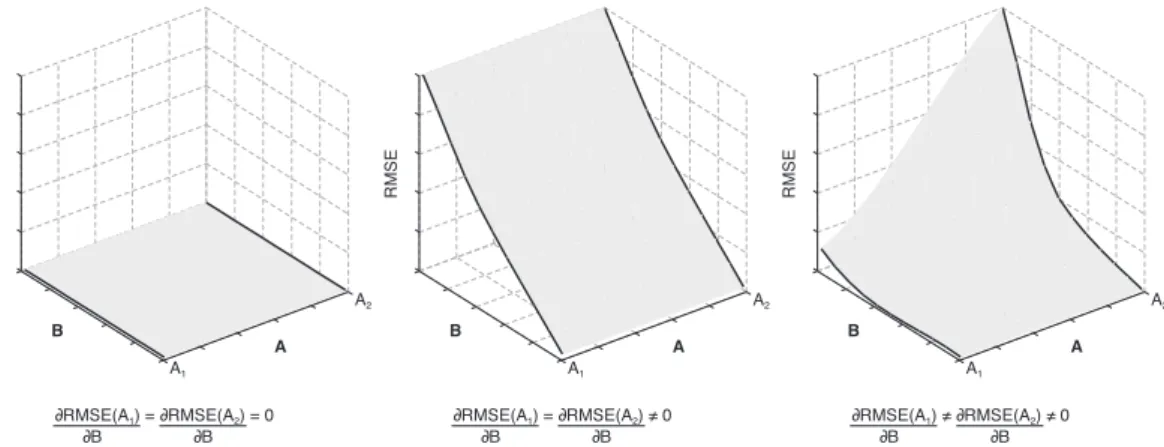
parameter combinations. The final analysis of parameter sensitivity on an idealized example is subdivided into: (1) insensitive parameters, (2) one sensitive parameter and (3) both parameters are sensitive (see Fig. 1 from left to right). In the latter case parameter A may be more sensitive for a certain range of parameter B, i.e.
δRMSE(A1)
δB 6=
δRMSE(A2)
δB 6=0. (25)
20
This case is particularly important if a properly calibrated model can be achieved for two different parameter combinations where at least one parameter is a pure calibration parameter, i.e. its range is difficult to estimate by field observations. Therefore, more than 1000 model runs were performed and the influence of parameter combinations on the simulated discharge curve analyzed.
HESSD
9, 1515–1546, 2012Simulation of saturated and unsaturated flow in
karst systems
J. Kordilla et al.
Title Page
Abstract Introduction
Conclusions References
Tables Figures
◭ ◮
◭ ◮
Back Close
Full Screen / Esc
Printer-friendly Version Interactive Discussion
Discussion
P
a
per
|
Dis
cussion
P
a
per
|
Discussion
P
a
per
|
Discussio
n
P
a
per
|
3 Case study
3.1 Description of the field site
The HydroGeoSphere model is employed to simulate flow in the catchment area of the Gallusquelle spring from February 1988 to January 1990. The Gallusquelle spring is situated in Southwest Germany on the Swabian Alb, a northeast-southwest
strik-5
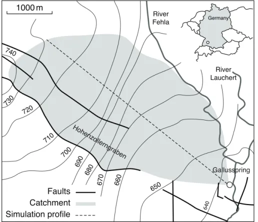
ing Jurassic carbonate plateau. The catchment area has been studied extensively by several authors including aquifer characterization (Birk et al., 2005; Sauter, 1992), speleology (Abel et al., 2002; Gwinner, 1976), and flow processes (Geyer et al., 2008). The size of the catchment is about 45 km2. It is delineated by a water divide in the northwest and the River Fehla in the northeast (see Fig. 2). In the south the catchment
10
is bounded by the northeastern fault zone of the Hohenzollerngraben, which was found to be impermeable by tunneling works in the 1960’s. After Sauter (1992) the base of the aquifer is formed by Kimmeridge marls (ki1). With a 70 m to 90 m thickness, this unit is rather consistent in the northwestern parts of the project area and consists of calcareous marls and occasional limestone intercalations. In the southeastern area no
15
borehole information about the lower boundary of the unit are available. The uppermost catchment is made up of a sequence of Kimmeridgian limestones (ki2–5) from which the majority is developed as algal-sponge facies and, therefore, belongs to the Un-terer Massenkalk or Oberer Massenkalk. The largest part of the catchment comprises limestones belonging to the Unterer Massenkalk (ki2 and ki3). The whole Jurassic
20
sequence dips southeast at an angle of 1.2◦.
3.2 Geometry of the flow model
Based on the geological model, a vertical two-dimensional model domain of the catch-ment area was set up (Fig. 3). The length of the domain is 10 km with a vertical thick-ness of 225 m. It reflects a cross section parallel to the direction of flow in the
Gal-25
HESSD
9, 1515–1546, 2012Simulation of saturated and unsaturated flow in
karst systems
J. Kordilla et al.
Title Page
Abstract Introduction
Conclusions References
Tables Figures
◭ ◮
◭ ◮
Back Close
Full Screen / Esc
Printer-friendly Version Interactive Discussion
Discussion
P
a
per
|
Dis
cussion
P
a
per
|
Discussion
P
a
per
|
Discussio
n
P
a
per
|
in the low permeability fissured matrix (matrix continuum) and the highly permeable
conduits (conduit continuum). The top of the model domain is set to 775 m a.s.l., which
is an average elevation between ca. 910 m a.s.l. in the north-western part of the catch-ment and ca. 640 m a.s.l. in the south-eastern catchcatch-ment and higher than the maximum groundwater head in the catchment. Every continuum is spatially discretized into 50
5
columns with a length of 200 m and a width of 1 m and 44 layers with a thickness of 5 m (Fig. 3).
3.3 Boundary conditions
The lateral sides of the matrix continuum and of the conduit continuum, as well as the top of the conduit continuum are defined as no flow boundaries (see Fig. 4). A constant
10
head boundary is applied to the right side of the conduit continuum at 634 m a.s.l. to represent the spring and allow discharge. A specified flux boundary is set at the top of the matrix continuum to account for diffuse recharge. Daily data of total recharge was estimated by Geyer (2008) for the simulation period on the Gallusquelle catch-ment. The applied water balance approach accounts for canopy storage, snow storage
15
and soil-moisture storage before water entering the bedrock. A second specified flux boundary is set on the bottom of the whole conduit continuum to add rapid recharge in the aquifer. The location of the boundary condition considers that the transit time of the rapid recharge component through the unsaturated zone is below one day (Geyer et al., 2008) and, therefore, negligible with regard to the daily time steps. The
simula-20
tion of rapid water percolation from the top of the conduit continuum to the groundwater surface is physically not possible with the van Genuchten approach, because it does not consider gravity driven flow processes like film and droplet flow. The initial head distribution for transient discharge simulations is computed with a steady state simu-lation. The applied total recharge for the simulation is 1.5 mm d−1, which corresponds
25
HESSD
9, 1515–1546, 2012Simulation of saturated and unsaturated flow in
karst systems
J. Kordilla et al.
Title Page
Abstract Introduction
Conclusions References
Tables Figures
◭ ◮
◭ ◮
Back Close
Full Screen / Esc
Printer-friendly Version Interactive Discussion
Discussion
P
a
per
|
Dis
cussion
P
a
per
|
Discussion
P
a
per
|
Discussio
n
P
a
per
|
estimated by Sauter (1997) from event analysis using oxygen isotopes in precipitation and Gallusquelle spring water to differentiate between different flow components.
3.4 Parameterization
For the model calibration, known parameters are only varied within reasonable ranges that agree with actual field observations (Table 1). Unknown model parameters are
in-5
vestigated by an extensive sensitivity analysis. The specific storage coefficients for ma-trix and conduits are negligible since the aquifer is unconfined; hence, water released due to compaction in the saturated zone is irrelevant. As there are no documented values for the hydraulic properties of the interface available, the van Genuchten pa-rametersαi,βi,Swriand the interface hydraulic conductivityKiwere set to values equal
10
to the surrounding fissured matrix. Accordingly, inter-continuum water exchange is solely controlled by adjusting the exchange parameterαex. Model calibration is
accom-plished by fitting the observed and simulated discharge curves. Finally, the flow model contains 21 adjustable parameters for the fissured matrix and the conduit continuum.
4 Results and discussion
15
Model calibration
The calibrated model shows a good fit with most of the specific characteristics of the discharge hydrograph during the period between 16 February 1988 and 20 January 1990 (see Fig. 5). Calibrated values for all varied parameters are comparable to values documented in the literature (Table 1). The observed discharge curve shows less sharp
20
peaks and is smoother than the simulated curve.
HESSD
9, 1515–1546, 2012Simulation of saturated and unsaturated flow in
karst systems
J. Kordilla et al.
Title Page
Abstract Introduction
Conclusions References
Tables Figures
◭ ◮
◭ ◮
Back Close
Full Screen / Esc
Printer-friendly Version Interactive Discussion
Discussion
P
a
per
|
Dis
cussion
P
a
per
|
Discussion
P
a
per
|
Discussio
n
P
a
per
|
data during the time period of the first peak. During the second discharge event (sec-ondary peak) the simulated peak height is overestimated. It is not possible to change the relative peak height difference between the primary and secondary peak with the available calibration parameters. The recession curve slopes after discharge events show a good fit, except during low flow conditions between July and October 1989.
5
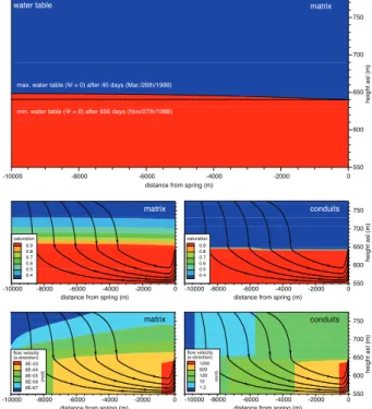
This behavior could be attributed to the simplified geometry of the numerical model, which does not include the documented slightly inclined aquifer base and the geome-try of different karstified zones in the karst system. The hydraulic heads in the matrix continuum and the conduit continuum are nearly identical during the simulation period (see Fig. 6) with a difference of a few centimeters. Above the water table the matrix
10
saturation drops to 0.35 near the surface. Flow paths in the unsaturated matrix contin-uum and conduit contincontin-uum are nearly vertical towards the groundwater table, whereas flow in the saturated zone is laterally oriented towards the outlet, i.e. the karst spring. The saturation in the conduit continuum is close to zero and has a very sharp transition along the water table. In this model, unsaturated flow in the conduits is also calibrated
15
by the krminc parameter (minimum relative permeability of the conduits). Without this
parameter, the relative permeability of the conduit continuum is a function of the resid-ual saturation, i.e. setting ofkrminc simply overrides Eq. (12). This is the case for most
of the unsaturated conduit continuum, where saturation declines very quickly (below 0.05) above the water table for the given van Genuchten parameters. Therefore, with
20
the applied van Genuchten parameters only, water flow in the unsaturated conduit con-tinuum is extremely small such that exchange from the matrix into the conduit system is nearly completely prevented and a proper model calibration is impossible. However, Tokunaga and Wan (1997) showed that gravity driven film flow processes occur on un-saturated fracture walls, which contribute to water percolation along surfaces and may
25
act as an interface from the conduit system to the matrix system, thus giving a physical meaning to thekrmincparameter. As the original van Genuchten model relies on a
HESSD
9, 1515–1546, 2012Simulation of saturated and unsaturated flow in
karst systems
J. Kordilla et al.
Title Page
Abstract Introduction
Conclusions References
Tables Figures
◭ ◮
◭ ◮
Back Close
Full Screen / Esc
Printer-friendly Version Interactive Discussion
Discussion
P
a
per
|
Dis
cussion
P
a
per
|
Discussion
P
a
per
|
Discussio
n
P
a
per
|
van Genuchten approach and include hydraulic features of fractures into a continuum model have been made for example by Ross and Smettem (1993), Durner (1994) and Brouy `ere (2006) by constructing a continuous bi-modal retention curve.
An important role for the water exchange in the double continuum approach plays the exchange parameter αex. It determines the ability of water to move in and out of the
5
conduit continuum and lumps geometrical and hydraulic properties of the karst matrix system. The surface-volume ratio, for example, is higher for a dendritic system than for a single conduit with the same conduit volume. The exchange parameter in the calibrated model is set to a high value such that it does not act as an additional barrier for water transfer between both continua and water transfer is mainly controlled by the
10
hydraulic properties of the two continua.
5 Sensitivity analysis
5.1 Single variation of hydraulic parameters for saturated flow conditions
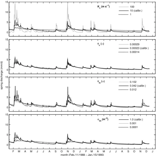
Figure 7 shows the computed spring discharge for several model runs with varying hydraulic conductivityKc and porosity θc in the conduit continuum. These parameters
15
strongly influence the simulated spring discharge. An increased conduit conductivityKc
results in sharp discharge peaks, very steep recession curves and low base flow levels because the water is quickly released from the conduit continuum. Decreased conduit conductivity Kc favors a slow recession and flattens the discharge curve. Discharge
peaks are broadened and base flow is higher. In case the conduit drains the matrix
20
system an increase of Kc enhances the exchange process between matrix and con-duits by decreasing the hydraulic gradient in the conduit continuum and consequently increasing the hydraulic gradient between matrix and conduits. Similar effects are ob-served for a variation of the conduit porosityθc. A contrasting behavior is observed by a variation in matrix porosity θm. With an increase in the parameter the water
trans-25
HESSD
9, 1515–1546, 2012Simulation of saturated and unsaturated flow in
karst systems
J. Kordilla et al.
Title Page
Abstract Introduction
Conclusions References
Tables Figures
◭ ◮
◭ ◮
Back Close
Full Screen / Esc
Printer-friendly Version Interactive Discussion
Discussion
P
a
per
|
Dis
cussion
P
a
per
|
Discussion
P
a
per
|
Discussio
n
P
a
per
|
difference between conduit and matrix and the discharge curve is smoothened ac-cordingly (see Fig. 7). Km displays a low sensitivity within the given parameter range
(see Table 2) which can be attributed to the high exchange parameter of the calibrated model ofαex=1.0. The high value leads to an immediate equalization of heads
be-tween conduit and matrix such that water will not be restrained within the matrix system
5
where total heads are slightly higher than within the conduit system. The matrix system always depends on the hydraulic state of the conduit continuum, which discharges wa-ter rapidly to the spring. However, in a three-dimensional karst system, flow velocities within the matrix will be little influenced by the conduit system with increasing distance to the conduit. The exchange parameterαex is sensitive only for strong reductions on
10
the order of three to four magnitudes. A reduction to 0.001 lowers the peak height of both main peaks while decreasing recession curve slopes and slightly increasing base levels. Further reduction to 0.0001 drastically decreases peak heights and increases the base levels. The resulting slopes of recession curves are very gentle and recharge events show no more pronounced peaks. An exchange reduction to 0.1 or 0.01 has
15
no significant influence on the discharge curves which indicates a sensitive interval between 0.001 and 0.0001.
5.2 Single variation of unsaturated zone parameters
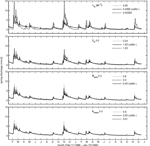
Variations of the sensitive van Genuchten parameters for the vadose zone are shown in Fig. 8. The decrease ofαmandβmresults in a strong rise of peak heights and increase
20
of recession slopes. The residual water saturation of the matrix system (Swrm) is less
sensitive with respect to the modeled hydrograph. The influence of the van Genuchten αm parameter on the discharge curve is connected to the inter-continuum water
ex-change process. Lowering the parameter increases the capillary rise, i.e. the matrix has higher saturation (and relative permeability) above the water table. Consequently
25
HESSD
9, 1515–1546, 2012Simulation of saturated and unsaturated flow in
karst systems
J. Kordilla et al.
Title Page
Abstract Introduction
Conclusions References
Tables Figures
◭ ◮
◭ ◮
Back Close
Full Screen / Esc
Printer-friendly Version Interactive Discussion
Discussion
P
a
per
|
Dis
cussion
P
a
per
|
Discussion
P
a
per
|
Discussio
n
P
a
per
|
3.65 where the saturation fringe declines very quickly with lower saturations above the water table. This reduces the main exchange interface to a smaller area above the water table. Thus during high recharge events, peak heights are reduced since wa-ter will remain longer in the matrix continuum. The van Genuchten paramewa-terβm can
be considered insensitive compared to αm. The conduit van Genuchten parameters
5
αc and βc are insensitive for the shown simulations. In the range of chosen values,
the conduits do not produce a strong capillary rise, i.e. the unsaturated zone above the conduit water table always displays a sharp transition from saturated to strongly unsaturated. As mentioned earlier the application of the van Genuchten parameters to a highly conductive and discrete flow system such as a conduit implies a general
10
abstraction of the physically based van Genuchten parameter set in order to create an upscaled continuum system with a characteristic infiltration behavior and travel time distribution as well as an exchange interface in the unsaturated zone. In this work the exchange process in the unsaturated zone can be controlled by theαcparameter in
or-der to increase the capillary rise in the conduit continuum and enhance inter-continuum
15
water transfer. However, such an approach also introduces a spatial information (i.e. the thickness of the conduit capillary fringe in vertical direction) which is not known in real karst systems. As described before thekrmincparameter is used instead to
main-tain a constant water exchange in the unsaturated zone independent of the hydraulic state of the conduit system if saturations are too low. The residual water saturation of
20
the matrixSwrmand the minimum relative permeability of the conduitskrmincboth show
a similar behavior regarding parameter variations. Increasing the parameters yields an enhanced exchange from the matrix to the conduit continuum due to a higher relative conductivity. Consequently recharge events are transmitted faster to the model outlet, i.e. the spring.
25
5.3 Combined parameter variations
HESSD
9, 1515–1546, 2012Simulation of saturated and unsaturated flow in
karst systems
J. Kordilla et al.
Title Page
Abstract Introduction
Conclusions References
Tables Figures
◭ ◮
◭ ◮
Back Close
Full Screen / Esc
Printer-friendly Version Interactive Discussion
Discussion
P
a
per
|
Dis
cussion
P
a
per
|
Discussion
P
a
per
|
Discussio
n
P
a
per
|
combinations may show non-linear behavior with respect to their sensitivity, i.e. the influence of one parameter on the RMSE is not linear over the whole range of a sec-ond parameter. For example, the simultaneous variation of the matrix van Genuchten parameter αm and the conduit conductivity Kc displays a pronounced sensitivity for
low αm values (Fig. 9). While for the calibrated αm value of 0.0365 m
−1
the conduit
5
conductivity Kc is almost insensitive in the range of 1–10 m s
−1
a lower αm value of
0.00365 m−1 yields a high RMSE of 1.6 mm d−1 already at a Kc value of 10 m s− 1
, i.e.δRMSE(αm=0.00365)/δKc is much higher. A similar behavior can be shown for a combination of matrix porosityθm and the conduit conductivity where lower
porosi-ties yield higher RMSE values with an increase in conduit conductivity to 100 m s−1
10
whereas for rather high matrix porosities of 0.102 the increase in RMSE is less pro-nounced. The conduit conductivityKcexhibits a higher sensitivity for the calibrated
ex-change parameterαex=1.0 (see Fig. 9) such that a high conductivity value (100 m s− 1
) results in RMSE values of ca. 1.4 mm d−1 while for a lower exchange parameter the same conductivity yields a deviation of only 0.4 mm d−1. The exchange parameter has
15
a higher sensitivity for high conductivity values of the conduit system while it is nearly insensitive for low values (1 m s−1). In sum, the variation of the exchange parameter influences the discharge curve depending on the combination with other parameters. This behavior can also be observed for the combination of matrix porosity θm and
exchange parameter αex. Here the exchange parameter has a higher sensitivity for
20
matrix porosities between 0.032 and 0.102 while at the lower limit (0.012–0.022) this sensitivity vanishes.
6 Conclusions
The applied double continuum model lumps the dual flow behavior of a karst aquifer, where conduits represent local features of the aquifer system. The advantage of the
25
HESSD
9, 1515–1546, 2012Simulation of saturated and unsaturated flow in
karst systems
J. Kordilla et al.
Title Page
Abstract Introduction
Conclusions References
Tables Figures
◭ ◮
◭ ◮
Back Close
Full Screen / Esc
Printer-friendly Version Interactive Discussion
Discussion
P
a
per
|
Dis
cussion
P
a
per
|
Discussion
P
a
per
|
Discussio
n
P
a
per
|
necessary. Due to their large volume, vertical conduits in a karst unsaturated system would act as flow barriers if simulated by the Richard’s equation. However, flow in vertical shafts is not controlled by matrix potential and capillary forces but rather flow processes dominated by gravitational forces such as film flow (Tokunaga and Wan, 1997; Tokunaga et al., 2000), turbulent film flow (Ghezzehei, 2004), droplet flow (Doe,
5
2001; Dragila and Weisbrod, 2004) and rivulet flow (Su et al., 2001, 2004; Dragila et al., 2004). In order to be able to use a consistent modeling approach, boundary con-ditions were modified and conduit recharge was directly injected at the bottom of the saturated conduit system. This procedure allows the simulation of rapid recharge with the given modeling code. The approach is successfully employed to simulate the
dis-10
charge curve of the karst system Gallusquelle for a period of two years. Because of the high amount of calibration parameters of the saturated-unsaturated flow model, a com-prehensive sensitivity analysis was performed. The analysis shows that the simulated discharge curve displays high sensitivity to a variation of a number of model parame-ters. The sensitivity study demonstrates that the simulation of karst hydraulics requires
15
a-priori knowledge about parameter ranges of model variables to reduce ambiguity of the model. However, especially for unsaturated zone parameters in double contin-uum karst systems, only little information about the parameter ranges is documented and further research is needed. Furthermore, the analysis shows that the sensitivity of a parameter depends to a large degree on the other calibrated model parameters.
20
Therefore, sensitivity analyses should simultaneously take into account parameters of both continua in order to detect deviations from a linear behavior if both parameters are sensitive. It also means that conclusions about parameter sensitivity change from model to model and are not simply transferable. The fissured matrix porosity as well as van Genuchten parameters of the matrix continuum are the most important parameters
25
HESSD
9, 1515–1546, 2012Simulation of saturated and unsaturated flow in
karst systems
J. Kordilla et al.
Title Page
Abstract Introduction
Conclusions References
Tables Figures
◭ ◮
◭ ◮
Back Close
Full Screen / Esc
Printer-friendly Version Interactive Discussion
Discussion
P
a
per
|
Dis
cussion
P
a
per
|
Discussion
P
a
per
|
Discussio
n
P
a
per
|
high flow velocities in the conduits it is apparent that strictly Darcian flow will underes-timate the heads (no energy loss due to friction) and consequently the exchange from matrix to conduits when the conduit continuum is draining the matrix system. More re-alistic results may be obtained by evaluating these influences for example by applying turbulent flow in the conduit continuum (Shoemaker, 2008; Reimann et al., 2011b). The
5
van Genuchten parameters of the matrix are the most crucial property in terms of sen-sitivity, uncertainty and model limitations. The exchange process between matrix and conduit continuum is mainly controlled by differences in hydraulic properties. Theαex
parameter was set to a rather high value during the calibration, i.e. exchange is not lim-ited by a too low exchange coefficient. According to Gerke and Van Genuchten (1993)
10
the parameter is defined to express the interface connectivity on a rather small scale, e.g. between a porous medium and macropores. On catchment scale it might implicitly correspond to the type of conduit system (i.e. dendritic vs. large single conduits). If the parameter is used to calibrate the model by limiting water transfer between continua, attention should be paid to the non-linear behavior of certain parameter combinations
15
and their resulting sensitivities. The application of van Genuchten parameters to frac-tured aquifer systems treats them as upscaled calibration parameters. Local scale flow processes, e.g. film and droplet flow along fracture surfaces, are not physically repre-sented. Additionally, the dual-continuum approach lumps the geometrical features of the conduit system and the fissured matrix blocks, respectively, in the saturated and
20
unsaturated zone.
References
Abel, T., Sauter, M., and Hinderer, M.: Karst genesis of the Swabian Alb, South Germany, since the Pliocene, Acta Geol. Pol., 52, 43–54, 2002. 1523
Bamberg, G., Baur, F., and Krapp, M.: Statistik, Oldenbourg, M ¨unchen, 2007. 1522 25
HESSD
9, 1515–1546, 2012Simulation of saturated and unsaturated flow in
karst systems
J. Kordilla et al.
Title Page
Abstract Introduction
Conclusions References
Tables Figures
◭ ◮
◭ ◮
Back Close
Full Screen / Esc
Printer-friendly Version Interactive Discussion
Discussion
P
a
per
|
Dis
cussion
P
a
per
|
Discussion
P
a
per
|
Discussio
n
P
a
per
|
Birk, S., Geyer, T., Liedl, R., and Sauter, M.: Process-based interpretation of tracer tests in carbonate aquifers, Ground Water, 43, 381–388, 2005. 1517, 1523
Birk, S., Liedl, R., and Sauter, M.: Karst spring responses examined by process-based model-ing, Ground Water, 44, 832–836, doi:10.1111/j.1745-6584.2006.00175.x, 2006. 1517
Brouy `ere, S.: Modelling the migration of contaminants through variably
satu-5
rated dual-porosity, dual-permeability chalk, J. Contam. Hydrol., 82, 195–219,
doi:10.1016/j.jconhyd.2005.10.004, 2006. 1527
Contractor, D. N. and Jenson, J. W.: Simulated effect of vadose in ltration on water levels in the Northern Guam Lens Aquifer, J. Hydrol., 229, 232–254, 2000. 1522, 1536
Doe, T.: What do drops do? Surface wetting and network geometry effects on vadose-zone
10
fracture flow, in: Conceptual Models of Flow and Transport in the Fractured Vadose Zone, chap. 8, National Academy Press, Washington, D.C., 243–270, 2001. 1531
Dragila, M. I. and Weisbrod, N.: Flow in menisci corners of capillary rivulets, Vadose Zone J., 3, 1439–1442, 2004. 1531
Dragila, M. I., Weisbrod, N., and Council, N. R.: Fluid motion through an unsaturated fracture 15
junction, Water Resour. Res., 40, 1–11, doi:10.1029/2003WR002588, 2004. 1531
Dreiss, S. J.: Regional scale transport in a karst aquifer: 1. Component separation of spring flow hydrographs, Water Resour. Res., 25, 117–125, 1989. 1517
Durner, W.: Hydraulic conductivity estimation for soils with heterogeneous pore structure, Water Resour. Res., 30, 211–223, doi:10.1029/93WR02676, 1994. 1527
20
Gerke, H. and Van Genuchten, M.: Evaluation of a first-order water transfer term for variably saturated dual-porosity flow models, Water Resour. Res., 29, 1225–1238, 1993. 1521, 1532 Geyer, T.: Process-based characterisation of flow and transport in karst aquifers at catchment
scale, Ph.D. thesis, University of G ¨ottingen, 2008. 1524
Geyer, T., Birk, S., Liedl, R., and Sauter, M.: Quantification of temporal distribution
25
of recharge in karst systems from spring hydrographs, J. Hydrol., 348, 452–463, doi:10.1016/j.jhydrol.2007.10.015, 2008. 1523, 1524
Ghezzehei, T. A.: Constraints for flow regimes on smooth fracture surfaces, Water Resour. Res., 40, 1–14, doi:10.1029/2004WR003164, 2004. 1531
Gwinner, M. P.: Origin of the Upper Jurassic limestones of the Swabian Alb (Southwest Ger-30
many), E. Schweizerbart, 1976. 1523
HESSD
9, 1515–1546, 2012Simulation of saturated and unsaturated flow in
karst systems
J. Kordilla et al.
Title Page
Abstract Introduction
Conclusions References
Tables Figures
◭ ◮
◭ ◮
Back Close
Full Screen / Esc
Printer-friendly Version Interactive Discussion
Discussion
P
a
per
|
Dis
cussion
P
a
per
|
Discussion
P
a
per
|
Discussio
n
P
a
per
|
Jeannin, P. Y.: Modeling flow in phreatic and epiphreatic karst conduits, Water Resour. Res., 37, 191–200, 2001. 1517
Mualem, Y.: A new model for predicting the hydraulic conductivity of unsaturated porous media, Water Resour. Res., 12, 513–522, 1976. 1520
Reimann, T., Geyer, T., Shoemaker, W. B., Liedl, R., and Sauter, M.: Effects of dynamically
5
variable saturation and matrix-conduit coupling of flow in karst aquifers, Water Resour. Res., 47, 1–19, doi:10.1029/2011WR010446, 2011a. 1517
Reimann, T., Rehrl, C., Shoemaker, W. B., Geyer, T., and Birk, S.: The significance of tur-bulent flow representation in single-continuum models, Water Resour. Res., 47, 1–15, doi:10.1029/2010WR010133, 2011b. 1517, 1532
10
Richards, L. A.: Capillary conduction of liquids through porous mediums, Physics, 1, 318–333, doi:10.1063/1.1745010, 1931. 1518
Ross, P. J. and Smettem, K. R. J.: Describing soil hydraulic properties with sums of simple functions, Soil Sci. Soc. Am. J., 57, 26–26, 1993. 1527
Roulier, S., Baran, N., Mouvet, C., Stenemo, F., Morvan, X., Albrechtsen, H.-J.,
15
Clausen, L., and Jarvis, N.: Controls on atrazine leaching through a soil-unsaturated fractured limestone sequence at Br ´evilles, France, J. Contam. Hydrol., 84, 81–105, doi:10.1016/j.jconhyd.2005.12.004, 2006. 1522, 1536
Sauter, M.: Quantification and Forecasting of Regional Groundwater Flow and Transport in a Karst Aquifer (Gallusquelle, Malm, SW Germany), T ¨ubinger Geowissenschaftliche Ar-20
beiten, 1992. 1517, 1522, 1523, 1536
Sauter, M.: Differentiation of flow components in a karst aquifer using theδ18O signature, in: Tracer Hydrology, edited by: Kranjc, A., Balkema, 435–441, 1997. 1525
Sauter, M., Geyer, T., Kovacs, A., and Teutsch, G.: Modellierung der Hydraulik von
Karstgrund-wasserleitern – Eine ¨Ubersicht, Grundwasser, 3, 143–156, doi:10.1007/s00767-006-0140-0,
25
2006. 1517
Shoemaker, W. B.: Documentation of a conduit flow process (CFP) for MODFLOW-2005, US Dept. of the Interior, US Geological Survey, 2008. 1532
Smart, P. L. and Hobbs, S. L.: Characterisation of carbonate aquifers: a conceptual base, in: Proceedings of the Environmental Problems in Karst Terranes and Their Solutions Confer-30
ence, Bowling Green, KY, NWWA, 17–31, 1986. 1517
HESSD
9, 1515–1546, 2012Simulation of saturated and unsaturated flow in
karst systems
J. Kordilla et al.
Title Page
Abstract Introduction
Conclusions References
Tables Figures
◭ ◮
◭ ◮
Back Close
Full Screen / Esc
Printer-friendly Version Interactive Discussion
Discussion
P
a
per
|
Dis
cussion
P
a
per
|
Discussion
P
a
per
|
Discussio
n
P
a
per
|
Su, G. W., Geller, J. T., Hunt, J. R., and Pruess, K.: Small-scale features of gravity-driven flow in unsaturated fractures, Vadose Zone J., 3, 592–601, 2004. 1531
Teutsch, G.: Grundwassermodelle im Karst: Praktische Ans ¨atze am Beispiel zweier Einzugs-gebiete im Tiefen und Seichten Malmkarst der Schw ¨abischen Alb, Ph.D. thesis, Universit ¨at T ¨ubingen, 1988. 1517
5
Teutsch, G. and Sauter, M.: Groundwater modeling in karst terranes: scale effects, data
ac-quisition and field validation, in: Proc. third Conf. Hydrogeology, Ecology, Monitoring, and Management of Ground Water in Karst Terranes, Nashville, TN, 17–35, 1991. 1517
Therrien, R. and Sudicky, E. A.: Three-dimensional analysis of variably-saturated flow and solute transport in discretely-fractured porous media, J. Contam. Hydrol., 3542, 1–44, 1996. 10
1517
Therrien, R., McLaren, R., Sudicky, E., and Panday, S.: HydroGeoSphere: a three-dimensional numerical model describing fully-integrated subsurface and surface flow and solute transport, Manual (Draft), HydroGeoLogic Inc., Herndon, VA, 2006. 1516, 1518
Tokunaga, T. K. and Wan, J.: Water film flow along fracture surfaces of porous rock, Water 15
Resour. Res., 33, 1287, doi:10.1029/97WR00473, 1997. 1526, 1531
Tokunaga, T. K., Wan, J., and Sutton, S. R.: Transient film flow on rough fracture surfaces, Water Resour. Res., 36, 1737–1746, 2000. 1531
van Genuchten, M. T.: A closed-form equation for predicting the hydraulic
conductivity of unsaturated soils, Soil Sci. Soc. Am. J., 44, 892–898,
20
doi:10.2136/sssaj1980.03615995004400050002x, 1980. 1519
HESSD
9, 1515–1546, 2012Simulation of saturated and unsaturated flow in
karst systems
J. Kordilla et al.
Title Page
Abstract Introduction
Conclusions References
Tables Figures
◭ ◮
◭ ◮
Back Close
Full Screen / Esc
Printer-friendly Version Interactive Discussion
Discussion
P
a
per
|
Dis
cussion
P
a
per
|
Discussion
P
a
per
|
Discussio
n
P
a
per
|
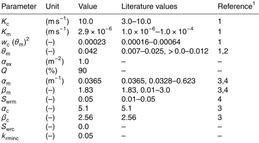
Table 1. Estimated values for the flow model derived from the model calibration and value ranges reported in the literature. Subscript m and c denote the matrix resp. the conduit contin-uum.
Parameter Unit Value Literature values Reference1
Kc (m s−
1
) 10.0 3.0–10.0 1
Km (m s−1) 2.9×10⁻⁶ 1.0×10⁻⁶–1.0×10⁻⁴ 1
wc(θm)2 (–) 0.00023 0.00016–0.00064 1
θm (–) 0.042 0.007–0.025,>0.0–0.012 1,2
αex (m−2) 1.0 – –
Q (%) 90 – –
αm (m−1) 0.0365 0.0365, 0.0328–0.623 3,4
βm (–) 1.83 1.83, 0.01–3.0 3,4
Swrm (–) 0.05 0.01–0.05 4
αc (–) 5.1 5.1 3
βc (–) 2.56 2.56 3
Swrc (–) 0.0 – –
krminc (–) 0.05 – –
1Conduit continuum porosity is 1.0 i.e.w
cθc=θtotal−wmθmimplicitly gives the conduit porosity.
HESSD
9, 1515–1546, 2012Simulation of saturated and unsaturated flow in
karst systems
J. Kordilla et al.
Title Page
Abstract Introduction
Conclusions References
Tables Figures
◭ ◮
◭ ◮
Back Close
Full Screen / Esc
Printer-friendly Version Interactive Discussion
Discussion
P
a
per
|
Dis
cussion
P
a
per
|
Discussion
P
a
per
|
Discussio
n
P
a
per
|
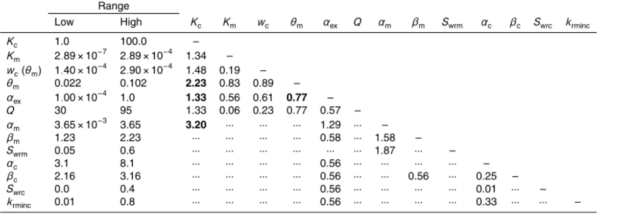
Table 2.Parameter combinations used for the sensitivity analyses and highest RMSE (mm d−1) observed. Bold RMSE values denote a non-linear inter-parameter dependence.
Range
Low High Kc Km wc θm αex Q αm βm Swrm αc βc Swrc krminc
Kc 1.0 100.0 –
Km 2.89×10
−7
2.89×10⁻⁴ 1.34 –
wc(θm) 1.40×10− 4
2.90×10⁻⁴ 1.48 0.19 –
θm 0.022 0.102 2.23 0.83 0.89 –
αex 1.00×10−
4
1.0 1.33 0.56 0.61 0.77 –
Q 30 95 1.33 0.06 0.23 0.77 0.57 –
αm 3.65×10−
3
3.65 3.20 ··· ··· ··· 1.29 ··· –
βm 1.23 2.23 ··· ··· ··· ··· 0.58 ··· 1.58 –
Swrm 0.05 0.6 ··· ··· ··· ··· ··· ··· 1.87 ··· –
αc 3.1 8.1 ··· ··· ··· ··· 0.56 ··· ··· ··· ··· –
βc 2.16 3.16 ··· ··· ··· ··· 0.56 ··· ··· 0.56 ··· 0.25 –
Swrc 0.0 0.4 ··· ··· ··· ··· 0.56 ··· ··· ··· ··· 0.01 ··· –
HESSD
9, 1515–1546, 2012Simulation of saturated and unsaturated flow in
karst systems
J. Kordilla et al.
Title Page
Abstract Introduction
Conclusions References
Tables Figures
◭ ◮
◭ ◮
Back Close
Full Screen / Esc
Printer-friendly Version Interactive Discussion
Discussion
P
a
per
|
Dis
cussion
P
a
per
|
Discussion
P
a
per
|
Discussio
n
P
a
per
|
RMSE
A B
A B
RMSE
A B
RMSE
A1
A2
A1
A2
A1
A2
∂RMSE(A1) = ∂RMSE(A2) ≠ 0
∂B ∂B
∂RMSE(A1) = ∂RMSE(A2) = 0
∂B ∂B
∂RMSE(A1) ≠ ∂RMSE(A2) ≠ 0
∂B ∂B
HESSD
9, 1515–1546, 2012Simulation of saturated and unsaturated flow in
karst systems
J. Kordilla et al.
Title Page
Abstract Introduction
Conclusions References
Tables Figures
◭ ◮
◭ ◮
Back Close
Full Screen / Esc
Printer-friendly Version Interactive Discussion
Discussion
P
a
per
|
Dis
cussion
P
a
per
|
Discussion
P
a
per
|
Discussio
n
P
a
per
|
Hohenzollerngraben
River Lauchert River
Fehla
670 660
650
640 680
690
720
730
740
700 710
Gallusspring
Germany
Faults Catchment Simulation profile
1000 m
HESSD
9, 1515–1546, 2012Simulation of saturated and unsaturated flow in
karst systems
J. Kordilla et al.
Title Page
Abstract Introduction
Conclusions References
Tables Figures
◭ ◮
◭ ◮
Back Close
Full Screen / Esc
Printer-friendly Version Interactive Discussion
Discussion
P
a
per
|
Dis
cussion
P
a
per
|
Discussion
P
a
per
|
Discussio
n
P
a
per
|
3.508E+06
3.51E+06
3.512E+06
3.514E+06
3.516E+06 5.34E+06 5.342E+06
5.344E+06 5.346E+06
5.348E+06 3.508E+06
3.51E+06
3.512E+06
3.514E+06
3.516E+06 5.34E+06 5.342E+06
5.344E+06 5.346E+06 400
500 600 700 800 900 1000
500 600 700 800 900 1000
height asl (m)
northing (m) easting (m)
Hohenz
ollern Gr
aben
Fault
Hohenz
ollern Gr
aben
easting (m) northing (m)
height asl (m)
Gallusspring
Kimmeridgian 2-5
Kimmeridgian 1
Oxfordian 2
Main Aquifer
High Transmissive Zone
400 m 500 m 700 m
HESSD
9, 1515–1546, 2012Simulation of saturated and unsaturated flow in
karst systems
J. Kordilla et al.
Title Page
Abstract Introduction
Conclusions References
Tables Figures
◭ ◮
◭ ◮
Back Close
Full Screen / Esc
Printer-friendly Version Interactive Discussion
Discussion
P
a
per
|
Dis
cussion
P
a
per
|
Discussion
P
a
per
|
Discussio
n
P
a
per
|
550 600 650 700 750
-10000
-8000
-6000
-4000
-2000
0 Y
X Z
constant head (Dirichlet) 640 m asl (Ψ=0)
speciied lux (Neumann) top boundary of matrix
distance fro m spring (m)
height (m)
impermeable boundaries
Element Size:
1m
200 m
5m
dual-node approach: 2 nodes at same physical location
fractured ma trix (p
rimary c ontinuum) conduits (s
econda ry continuum
)
specified flux (Neumann) bottom boundary of bonduits
HESSD
9, 1515–1546, 2012Simulation of saturated and unsaturated flow in
karst systems
J. Kordilla et al.
Title Page
Abstract Introduction
Conclusions References
Tables Figures
◭ ◮
◭ ◮
Back Close
Full Screen / Esc
Printer-friendly Version Interactive Discussion
Discussion
P
a
per
|
Dis
cussion
P
a
per
|
Discussion
P
a
per
|
Discussio
n
P
a
per
|
F M A M J J A S O N D J F M A M J J A S O N D J
0 5 10 15
month (Feb./11/1988 − Jan./15/1990)
spring discharge (mm/d)
0
10
20
30
40
50
60
70
80
recharge (mm/d)
simulated observed recharge
HESSD
9, 1515–1546, 2012Simulation of saturated and unsaturated flow in
karst systems
J. Kordilla et al.
Title Page Abstract Introduction Conclusions References Tables Figures ◭ ◮ ◭ ◮ Back Close
Full Screen / Esc
Printer-friendly Version Interactive Discussion Discussion P a per | Dis cussion P a per | Discussion P a per | Discussio n P a per |
max. water table (Ψ = 0) after 45 days (Mar./26th/1988)
min. water table (Ψ = 0) after 656 days (Nov/27th/1988)
-10000 -8000 -6000 -4000 -2000 0 distance from spring (m)
-10000 -8000 -6000 -4000 -2000 0 distance from spring (m)
550 600 650 700 750
height asl (m)
550 600 650 700 750
height asl (m)
-10000 -8000 -6000 -4000 -2000 0
distance from spring (m)
550 600 650 700 750
height asl (m)
water table matrix
-10000 -8000 -6000 -4000 -2000 0 distance from spring (m)
Conduits flow velocity (x-direction) 8E-03 8E-04 8E-05 8E-06 8E-07 (m/d)
-10000 -8000 -6000 -4000 -2000 0 distance from spring (m)
Matrix flow velocity (x-direction) 1200 600 120 12 1.2 (m/d) saturation 0.9 0.8 0.7 0.6 0.5 0.4 conduits conduits matrix matrix saturation 0.9 0.8 0.7 0.6 0.5 0.4
Fig. 6. Results of the transient flow model (26 March 1988, lower four pictures). The water table height is nearly equal in both continuas during the whole simulation and differs 1 mm at
most. The van Genuchten parameterαm leads to a strong difference between the continuas.
HESSD
9, 1515–1546, 2012Simulation of saturated and unsaturated flow in
karst systems
J. Kordilla et al.
Title Page
Abstract Introduction
Conclusions References
Tables Figures
◭ ◮
◭ ◮
Back Close
Full Screen / Esc
Printer-friendly Version Interactive Discussion
Discussion
P
a
per
|
Dis
cussion
P
a
per
|
Discussion
P
a
per
|
Discussio
n
P
a
per
|
0 5 10 15
100 10 (calibr.) 1 K
c (m s −1)
0 5 10 15
0.00029 0.00023 (calibr.) 0.00014 θ
c (−)
0 5 10 15
0.102 0.042 (calibr.) 0.012 θ
m (−)
F M A M J J A S O N D J F M A M J J A S O N D J
0 5 10 15
month (Feb./11/1988 − Jan./15/1990)
spring discharge (mm/d)
1.0 (calibr.) 0.001 0.0001 α
ex (m
−2 )
HESSD
9, 1515–1546, 2012Simulation of saturated and unsaturated flow in
karst systems
J. Kordilla et al.
Title Page
Abstract Introduction
Conclusions References
Tables Figures
◭ ◮
◭ ◮
Back Close
Full Screen / Esc
Printer-friendly Version Interactive Discussion
Discussion
P
a
per
|
Dis
cussion
P
a
per
|
Discussion
P
a
per
|
Discussio
n
P
a
per
|
0 5 10 15
3.65 0.0365 (calibr.) 0.00365 α
m (m −1)
0 5 10 15
2.23 1.83 (calibr.) 1.23 β
m (−)
0 5 10 15
0.6 0.3 0.05 (calibr.) Swrm (−)
F M A M J J A S O N D J F M A M J J A S O N D J 0
5 10 15
month (Feb./11/1988 − Jan./15/1990)
spring discharge (mm/d)
0.8 0.05 (calibr.) 0.01 krminc (−)
HESSD
9, 1515–1546, 2012Simulation of saturated and unsaturated flow in
karst systems
J. Kordilla et al.
Title Page Abstract Introduction Conclusions References Tables Figures ◭ ◮ ◭ ◮ Back Close
Full Screen / Esc
Printer-friendly Version Interactive Discussion Discussion P a per | Dis cussion P a per | Discussion P a per | Discussio n P a per | 1 10 100 0.00365 0.0365 0.365 3.65 0 0.5 1 1.5 2 2.5 3 3.5
Kc (m/s)
α m (m
−1) RMSE (mm/d) 1 10 100 0.022 0.032 0.042 0.052 0.062 0.082 0.102 0 0.5 1 1.5 2 2.5 3 3.5
Kc (m/s)
θ m (−)
RMSE (mm/d) 1 10 100 0.0001 0.001 0.01 0.1 1 0 0.5 1 1.5 2 2.5 3 3.5
Kc (m/s)
α ex (m
−2 ) RMSE (mm/d) 0.0001 0.001 0.01 0.1 1 0.022 0.032 0.042 0.052 0.062 0.082 0.102 0 0.5 1 1.5 2 2.5 3 3.5 α ex (m
−2) θ
m(−)
RMSE (mm/d)