ISSN 1 5 1 7 - 7 0 7 6
Revista Matéria, v. 15, n. 2, pp. 233–239, 2010. http://www.materia.coppe.ufrj.br/sarra/artigos/artigo11221
Young’s modulus of Al/SiC
P/MgAl
2O
4composites with different particle
size distribution of reinforcements
M. Montoya-DávilaI; M.I. Pech-CanulII; R. Escalera-LozanoIII; M.A. Pech-CanulIV
I
Universidad Autónoma de Zacatecas, Carretera a la Bufa km 1, Zacatecas, Zac. México 98064. e-mail: [email protected]
II
Cinvestav Saltillo. Carr. Saltillo-Mty Km 13, Saltillo Coah. México 25900. e-mail: [email protected]
III
Universidad del ISTMO, Campus Tehuantepec. Ciudad Universitaria S/N, Barrio Santa Cruz, 4a. Sección Sto. Domingo Tehuantepec, Oax., México C.P. 70760.
e-mail: [email protected]
IV
Cinvestav Mérida. Km. 6 Antigua Carr. a Progreso Apdo. Postal 73, Cordemex. Mérida, Yuc., México 97310, Phone: +52 (844) 438-9600 Ext. 9678. Fax: + 52 (844) 438-9610
E-mail: [email protected]
ABSTRACT
The effect of particle size distribution of SiC particulate reinforcements coated with colloidal SiO2
on Young´s modulus of Al/SiCp/MgAl2O4 composites fabricated by reactive infiltration was investigated.
Composites were prepared from porous preforms of silica-coated α- SiC powders of 10, 54, 86, and 146 μm, 0.6 volume fraction of reinforcements and particle size distribution from monomodal to cuatrimodal. Infiltration tests with the alloy Al-13.3Mg-1.8Si (wt. %) were carried out in Ar→N2 atmosphere at 1100ºC for 60 min. The composites were characterized by X-ray diffraction (XRD) and scanning electron microscopy (SEM). In addition to density and residual porosity measurements, Young´s modulus was evaluated by ultrasonic techniques. Results show that with increase in particles size distribution, residual porosity decreases and density and Young´s modulus of the composites are improved, the latter from 185.39 ±3.6 to 201.93 ±2.3 GPa. This is attributed to the increased metal-ceramic interfaces and to an enhanced matrix-reinforcement load transmission.
Keywords: Al/SiCp/MgAl2O4 composites, multimodal distribution, Young’s modulus.
1 INTRODUCTION
Aluminum-matrix-composites (AMCs) reinforced with SiC particles have received considerable attention over the last three decades due to the attractive properties resulting from the combination of their constituents, such as high thermal conductivity, specific strength, tailorable coefficient of thermal expansion, improved modulus of rupture, Young´s modulus and low density. For this reason, they have been considered for applications in the aerospace, military, automotive, and electronic industries [1, 2, 3]. As for the latter, Al/SiC composites have been proposed for electronic packaging as heat sink parts in microwave housing and chip carriers. For these types of applications it is essential to increase the volume fraction of the ceramic reinforcement in excess of 50 vol. % [2]. When the Al/SiC composites are fabricated by the liquid metal infiltration route, this requirement can be met by accommodating reinforcements of different sizes into the porous ceramic preform. But for a fixed volume fraction of the reinforcements, the composites exhibit different characteristics when the particle size distribution is changed.
The aim of this work was study the effect of particles size distribution of SiC reinforcements on Young´s modulus of Al/SiC/MgAl2O4 composites fabricated by the pressureless infiltration method. In order
to evaluate the elastic modulus, non-destructive tests were conducted, using ultrasonic techniques, where the longitudinal velocity of ultrasonic wave (VL) is measured and using a relation between Poison´s ratio ( ),
( ) ( )(
)
[
1/2]
2
1
1
/
1
−
υ
ρ
+
υ
−
υ
=
E
V
L (1)In equation (1), VL corresponds to the longitudinal velocity of ultrasonic wave, is Poisson´s ratio,
E is Young´s modulus and ρ the density.
2 EXPERIMENTAL PROCEDURES
Ceramic preforms with 0.60 volume fraction of ceramic material (0.5 vol. fraction α-SiC + 0.1 vol. fraction of SiO2 in the form of coatings on the SiC particles) were prepared by properly mixing four distinct
particle sizes of the SiC reinforcement (10, 54, 86 and 146 μm), in such a way that the combinations yielded porous bodies with monomodal, bimodal, trimodal, and cuatrimodal size distribution, with 1, 1:5, 1:1:4 and 1:1:1:3 particle size ratios, respectively. In this context, particles of 10, 54, 86 and 146 μm are referred to as small, medium-1, medium-2, and large, correspondingly. Particle-size-ratio designation involves both, the preform type (monomodal, bimodal, trimodal, cuatrimodal) and the proportion of each particle size. Systematically, bimodal, trimodal, and cuatrimodal preforms consist of small/large, small/medium-1/large and small/medium-1/medium-2/large particles, respectively. For instance, 1:5 represents a bimodal preform prepared with one part of small particles and five parts of large ones; 1:1:1:3 stands for a cuatrimodal preform made up of one part of small particles, one part of medium-1 particles, one part of medium-2 particles, and three parts of large ones. Monomodal preforms are just designated with the corresponding particle size; for this particular case, the particle size was 146 μm.
In order to prevent attack of the SiC reinforcements by the liquid aluminum alloy during infiltration, the powders were previously coated with a colloidal suspension of SiO2 (0.02-0.06 µm particle size,
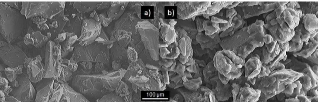
according to the supplier). The silica suspension was placed in a beaker and stirred at constant rate using a Barnant electromechanical mixer. In order to obtain a homogeneous mixture, the SiC powders were added gradually to the suspension during the stirring, while the system was heated at 50 °C in a Cimarec hot-plate-stirring system for 30 min. Figure 1 shows representative photomicrographs of uncoated and coated SiC particles. Finally, after drying the mixture in an air forced drier at ~ 200 oC for 2 hours, the powders were placed into a steel mould and compacted uniaxially (~ 3.5 MPa) using a hydraulic press to produce plate-shaped preforms of 3 cm x 4 cm x 0.5 cm.
Figure 1: Representative photomicrographs of uncoated and coated SiC particles.
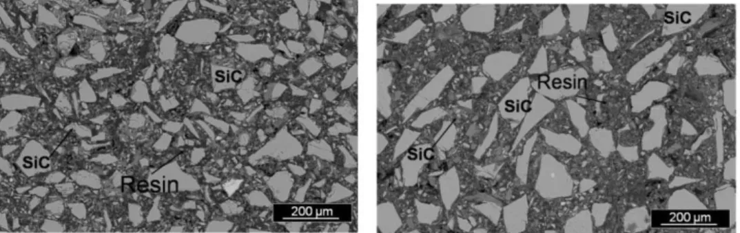
Figure 2: Representative photomicrographs of mounted specimens for pore size measurements.
Composites were fabricated by infiltrating the aluminum alloy Al-13.3Mg-1.8Si (wt. %) –purposely designed for the current investigation – into the ceramic preforms in a horizontal tube furnace with a 6.5 cm diameter alumina tube closed at both ends with end-cap fittings to control the process atmosphere. The aluminum alloy was fabricated from Al of commercial purity with additions of Mg and Si, in an induction furnace with capacity of 10 Kg. Previous to casting in a metallic mold, the alloy was degassed using argon gas at 680 °C for 10 min. The chemical composition of the aluminum alloy is given in Table 1.
Table 1: Chemical composition (wt %) and molar ratio Si/Mg of the aluminum alloy used.
Al Mg Si Fe Mn Cu Si/Mg
A1 Balance 13.29 1.78 0.626 0.118 0.055 0.116
The preform and approximately 32 g of the alloy were placed in a ceramic container and the whole assembly was positioned in the tube center. The system was heated at a rate of 15 °C/min up to 1100 °C, held at that temperature for 60 min and then cooled down with the same rate to room temperature. During the heating period and up to 1000 °C, the specimens were treated in ultra high purity (UHP) argon. Then, in order to enhance the wetting of the preform by the liquid alloy, a change in the atmosphere from Ar to UHP N2 was conducted at 1000 °C. Once the system was cooled down to room temperature, the composite
specimens were prepared for microstructure characterization using X-ray diffraction (XRD), scanning electron microscopy (SEM)) and energy dispersive X-ray spectroscopy (EDS). SEM analysis was conducted in a JEOL JSM 6300 scanning electron microscope in the backscattered electron mode at a working distance between 10-15 mm, and acceleration voltage of 20 KV. The composite specimens were prepared using metallographic procedures. The density was evaluated by means of Archimedes’ principle; and Young´s modulus was evaluated by means of non-destructive tests (ultrasonic techniques) using an Epoch 4 Panametrics ultrasonic equipment, and using equation (1) [4].
3 RESULTS AND DISCUSSION
3.1 Microstructure Characterization
Results from the characterization by X-ray diffraction showed the presence of the Mg2Si, MgAl2O4,
MgO and AlN phases in addition to Al, Si and SiC from the starting material. Figure 3 shows typical diffractograms corresponding to composites with monomodal, bimodal, trimodal, and cuatrimodal distributions. As expected, the SiO2 coatings helped protecting the SiC particles from being attacked by the
aluminum alloy and, in consequence, successfully avoided formation of the undesirable Al4C3 phase in the
composites.
The spinel, magnesium oxide, magnesium silicide, and aluminum nitride phases are formed in situ during processing according to
2 Al(l) + Mg(l) + 2 SiO2(s) = MgAl2O4(s) + 2 Si(s) (2)
ΔG1100ºC = - 484 kJ/mol
2 Mg + SiO2 = 2MgO + Si (3)
ΔG1100ºC = -253.04 kJ/mol
ΔH1100ºC = -295.7 kJ/mol
The presence of the AlN in the microstructure is explained through the reaction of molten aluminum and nitrogen gas according to [5]
Al(l) + [N] = AlN(S) (4)
ΔG1100°C =-325 kJ/mol
10 20 30 40 50 60 70 80
2
θ
(degrees)
Intensity (u.a)
Monomodal Trimodal Cuatrimodal Bimodal L T L T T z T T D L LD
L D D D D L z D Al AlN Si DSiC
LMgAl2O4 z MgO
T Mg2Si
L
D
D
Figure 3: Typical diffractograms of composites with monomodal, bimodal, trimodal and cuatrimodal
distributions.
Moreover, due to its lower vaporization temperature as compared with that for aluminum at normal pressure, magnesium escapes from the melt during processing. Previous reports indicate that Mg in vapor phase reacts with nitrogen and returns to the alloy according to the following reactions [6]
( )g
N
( )gMg
N
( )sMg
2
3 23
+
→
(5)ΔG1100°C= -90.70 kJ/mol
ΔH1100ºC = -183.03 kJ/mol
( )l
Mg
N
( )sAlN
( )sMg
( )gAl
2
3
2
+
3 2→
+
(6)ΔG1100ºC = -167.82 kJ/mol
ΔH1100ºC = -218.22 kJ/mol
The net effect of the recycling process –represented by Equations (5-6) – is to enhance the wettability of silicon carbide by the Al-Mg-Si alloy. The wetting enhancement mechanism has been extensively reported in the previous literature [6-8]. The analysis by XRD also showed that the type of phases formed in situ is not influenced by particle size distribution, because the same phases were formed in all the four kinds of composites. This in turn, is due to the protection provided by the silica coating.
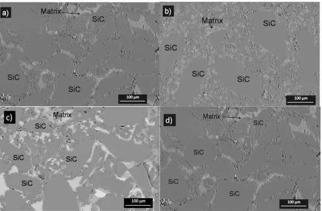
observed that the SiC particles do not seem to be attacked by the aluminum alloy and that they are surrounded by the spinel phase. This fairly explains the soundness of the reinforcements and the absence of the unwanted aluminum carbide phase.
Figure 4: Typical microstructures of the composites with monomodal, bimodal, trimodal, and cuatrimodal
distribution.
3.2 Mechanical Characterization
The density of the composites is augmented with increase in particle size distribution from monomodal to cuatrimodal, this is attributed to the better filling of porous preforms by aluminum alloy due to decrease in pores sizes. Table 2 shows the density values of Al/SiC/MgAl2O4 composites. These values are in
the range from 2.84 ±0.015 to 2.96 ±0.016, which are similar to those reported by C. Y. Chen et al. [9] in composited fabricated by pressure infiltration.
Table 2: Density and residual porosity of the Al/SiC/MgAl2O4 composites.
Composites Density (g/cm3) % Porosity
Monomodal 2.84 ±0.015 4.42 ±0.022
Bimodal 2.92 ±0.010 1.48 ±0.012
Trimodal 2.93 ±0.013 1.40 ±0.018
Cuatrimodal 2.96 ±0.016 0.49 ±0.010
According to the characterization of the preforms, the average pore sizes for monomodal, bimodal, trimodal and cuatrimodal distributions are 22.53 ± 2.65, 7.74 ± 1.3, 6.99 ± 1.24, and 6.55 ± 1.24 μm, respectively. It is clear that pore size drops by about 65 % from monomodal to bimodal; then, from bimodal to trimodal and cuatrimodal, the decrease is less significant. This outcome is explained by the accommodation of the small and medium particles in the space left by the large particles. It should be recalled that the pores in the ceramic preforms are filled out by the aluminum alloy during the infiltration process.
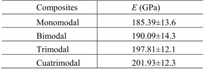
reported by Chang You Chen [9] in composites fabricated by pressure infiltration. Table 3 shows the values of the Young´s modulus of the Al/SiC/MgAl2O4 composites.
Table 2: Young´s modulus of the Al/SiC/MgAl2O4 composites.
Composites E (GPa)
Monomodal 185.39±13.6 Bimodal 190.09±14.3 Trimodal 197.81±12.1 Cuatrimodal 201.93±12.3
The values of Young’s modulus are augmented with increase in the particle size distribution. It's well kwon [10] that the reinforcement endures and transmits load through the metallic matrix. Accordingly, the increase in the values of Young´s modulus can be explained in two possible ways: 1) as a function of the test, which determines the velocity of the ultrasonic wave in the material; thus, increasing the particle size distribution the lesser the area of the matrix is, and the wave travels through the material with a minor velocity. 2) As a function of the mechanical behavior, when the particle distribution is high, the metal/ceramic interfases are increased, and in this way the percentage of borne stress is augmented.
4 SUMMARY AND CONCLUSIONS
The results of the study of the effect of particle size distribution on Young´s modulus of Al/SiC/MgAl2O4 composites prepared by the pressureless infiltration method can be summarized as follows:
Increasing the particle size distribution in the composites, the density is increased with values from 2.84 ±0.015 to 2.96 ±0.016. The values of Young´s modulus are augmented with increase in particle size distribution, in the range from 185.39 to 201.93 GPa for monomodal to cuatrimodal, respectively. These results are similar to those reported by C. Y. Chen [9] in composites prepared by pressure infiltration. Two possible explanations account for the observed behavior: 1) as a function of the test, which determines the velocity of ultrasonic wave in the material; thus, increasing the particle size distribution, the lesser the matrix area is, and the wave travels through the material with a lower velocity; 2) As a function of the mechanical behavior, when the distribution is high, the metal/ceramic interfases are increased, and in this way the level of borne stresses is augmented.
5 ACKNOWLEDGEMENTS
M. Montoya-Dávila gratefully acknowledges Conacyt for providing a doctoral scholarship; authors also thank Mrs. M. Rivas Aguilar for assistance during the characterization by SEM.
6 REFERENCES
[1] CUI, Y., “High volume fraction SiC/Al composites prepared by pressureless melt infiltration: processing, properties and applications”, Key Engineering Materials, v. 249, pp. 45-48, 2003.
[2] LEE, H.S., LEE, C.S., LEE, J.R., “Pressure infiltration casting process and thermal properties of high volume fraction SiCp/Al composites for electronic packaging”, Aluminum Transactions, v. 3, n. 1, pp. 1-6, 2000.
[3] PARDO, A., MERINO, M.C., MERINO, S., VIEJO, F., CARBONERAS, M., ARRABAL, R., “Influence of reinforcement proportion and matrix composition on pitting corrosion behaviour of cast aluminium matrix composites (A3xx.x/SiCp)”, Corrosion Science, v. 47, pp. 1750-1764, 2005. [4].GUR, C.H, OGEL, B., “Non-destructive microstructural characterization of aluminum matrix composites
by ultrasonic techniques”, Materials Characterization, v. 47, pp. 227-233, 2001.
[6] PECH-CANUL, M.I., KATZ, R.N., MAKHLOF, M.M., “The combined role of Nitrogen and magnesium in wetting SiC by aluminum alloys”, In: XXII International Congress of Metallurgy and Materials, Held in Saltillo Coahuila, México, pp. 232-241, November 8-10, 2000.
[7] REYES, M.R., PECH-CANUL, M.I., ANGELES, J.C.R., CUEVAS, J.L., “Limiting the development of Al4C3 to prevent degradation of Al/SiCp composites processed by pressureless infiltration”, Composites Science and Technology, v. 66, n. 8, pp. 1056-1062, 2006.
[8] HOU, Q., MUTHARASAN, R., KOCZAK, M., “Feasibility of aluminum nitride formation in aluminum alloys”, Materials Science and Engineering, v. 195A, pp. 121-129, 1995.
[9] CHEN, C.Y., CHAO, C.G., “Effect of particle-size distribution on the properties of high volume fraction SiC-Al-Based composites”, Metallurgical and Materials Transactions A, v. 31A, pp 2351-2359, 2000.