Short-term Creep Properties and Fracture Surface of 18 Ni (300) Maraging Steel Plasma
Nitrided
Adriano Gonçalves dos Reisa,b*, Danieli Aparecida Pereira Reisc,d, Antônio Jorge Abdallad,e, Antônio Augusto Coutob,f, Jorge Otuboc,d
Received: September 30, 2016; Revised: February 6, 2017; Accepted: February 18, 2017
Plasma nitriding of a solution annealed and aged 300 grade maraging steel was studied aiming to
increase the creep resistance. The surface microhardness reached 1,140 HV, producing 50 μm layer composed of ε-Fe3N and γ’-Fe4N nitrides at the uppermost sample layer. The inner core remained
unaltered presenting typical plate-like martensite microstructure of maraging steels with average
microhardness of 604 HV. Surface RMS roughness in the nanometric scale increase from 52 nm to 71 nm. The continuous layer of iron nitrides seems to behave as a barrier for oxidation and for inward
oxygen difusion improving the creep resistance by reducing the steady-state creep rate (εs) in 52-65%
when compared with the literature results. Dominant creep mechanism is controlled by dislocations
climb. Fracture surfaces of specimens presented ductile failure consisting of equiaxed and bi-modal dimples in the ibrous zone surrounded by 45º shear lip. Nitrided sample presented a reduced ductility,
associated to the hard surface layer.
Keywords: maraging, creep, plasma nitriding, fracture
* e-mail: [email protected]
1. Introduction
The 18-percent nickel 300 grade maraging steels belong
to a family of iron based alloys that are strengthened by a combination of martensite formation during a solution annealing followed by an aging treatment. Since 1959 when
their development was announced, maraging steels evoked
tremendous interest, especially in the aerospace world, due to the combination of structural strength and fracture toughness in a material that was, at the same time, readily weldable and
easy to heat-treat. The large rocket-motor program sparked
the considerable research and development of maraging
steels, and it is the key application until now. Otherwise,
currently maraging steels are applied not only for aerospace, military and nuclear industries, but also for transportation,
manufacturing, tooling, die making and electromechanical components. 300 grade maraging steel is a member of iron-nickel based alloy family with yield strength of 300 ksi1-4.
One of the major factors limiting the life of maraging steels
in service is their degradation due to gaseous environments, in particular, to environments containing oxygen at elevated
temperatures during long-term use. When maraging steels
are exposed in air, obey a limited oxide layer thickness growth law up to 480 ºC and a parabolic law above this temperature. At 500°C and up to 600°C, the growth rate is
faster and increases sharply with increase in temperature. The interaction of maraging steels with oxygen not only causes losses in the material during the formation of oxides but also
causes embrittlement in the subsurface zone of the component
due to oxygen enrichment, and the creep resistance is often
the limiting parameter in design under diferent
temperature-stress domains5-6. Therefore, for high temperature service in
oxidizing atmospheres, satisfactory creep resistance must
be combined with adequate resistance to environmental
degradation. Increasing eforts are being directed to the study of supericial thermochemical treatments to improve
oxidation and creep resistance of metals and alloys7-10. Plasma nitriding is a technique used to introduce elemental nitrogen
to the surface of a metal part for subsequent difusion into the
material by ion glow discharge. Plasma nitriding is specially designed for low temperature nitriding, and it is adequate for maraging steels avoiding the overaging11-13. Plasma nitriding of maraging steels has been extensively investigated with
the aim of improving the alloy’s tribological and mechanical
properties13-14. Otherwise, data available on the mechanical
a Universidade Estadual Paulista (Unesp), Instituto de Ciência e Tecnologia,
São José dos Campos, SP, Brazil
b Instituto de Pesquisas Energéticas e Nucleares – IPEN, São Paulo, SP, Brazil
c Instituto de Ciência e Tecnologia, Universidade Federal de São Paulo – UNIFESP, São José dos
Campos, SP, Brazil
d Instituto Tecnologico de Aeronautica – ITA, São José dos Campos, SP, Brazil e Instituto de Estudos Avançados – IEAv, São José dos Campos, SP, Brazil
followed by aging at 480 ºC – 3 h and then air cooled in a Brasimet Koe 40/25/65 furnace, hereafter called MAR-SA. Plasma nitriding was performed using a 30 kW DC-pulsed source at 480 ºC for 3 h in an environment atmosphere of 75% N2 – 25% H2, hereafter called MAR-SAP. The
microstructural characterization was carried out on Carl Zeiss model Axio Imager 2 optical microscopy - OM. XRD was carried out at room temperature with a CuKα radiation source on Panalytical model X´ Pert Powder difractometer. Data for each phase were analyzed with X’Pert HighScore using the ICDD database. Hardness was measured using Vickers microhardness Tester (FutureTech model FM-700) with load of 100 g for 9 s. Surface morphology was analyzed using Nanosurf Flex atomic force microscope - AFM (tapping
mode, SiN3 tip model NCHR, Nanoworld). Samples of 18.5 mm gauge length by 3.0 mm in diameter were submitted to
constant load creep tests at 650 ºC (200, 300 and 500 MPa),
600 ºC (500 MPa) and 550 ºC (500 MPa) in a standard Mayes creep machine, according to ASTM E139 standard19. Disks
for transmission electron microscopy (TEM) were sliced from the crept samples and pre-thinned by dimple grinder SBT
Model 515. Thin foils were then prepared by ion polishing
in a GATAN Model 691. Observations of the center of the foils were carried out in a FEI TECNAI model G2F20 TEM.
Fractographic analysis were carried out by scanning electron
microscopy - SEM (TESCAN model VEGA 3).
3. Results and Discussion
3.1. Microstructural characterization
Figure 1 is the cross-sectional image of MAR-SAP
showing an uniform and continuous hardened nitrided
layer of 50 μm thick and the typical martensite plate-like microstructure of maraging steels in the un-nitrided core.
The X-ray difraction (XRD) pattern in the 2θ ranging from 35–90º of MAR-SA and MAR-SAP samples are shown in Figure 2. MAR-SA exhibit difraction peaks only due to the martensitic phase α’-Fe, Figure 2a. After plasma nitriding
in Figure 3 reveals that the etched-out depth (50 μm) is the
depth of the layer where the nitride phase is predominant,
as proved in X-ray difraction in the Figure 2. Higher values
of microhardness are expected in this region. The band from
50 to 100 μm is the transition region where the hardness values decrease inward in a diferent rate, approaching the
hardness of the matrix. This is probably the region of solid solution hardening by nitrogen atoms. It should be noted
that the core hardness of MAR-SAP remains the same as that of MAR-SA. This conirms that the core does not soften
by overaging due to ion nitriding temperature and time. Plasma nitriding changed the topography on the surface
of MAR-SAP sample, according to the three-dimensional AFM images (Figure 4). The layer of iron nitrides being
formed led to an increase of surface RMS roughness in
the nanometric scale from 52 nm (MAR-SA), Figure 4a, to 71 nm (MAR-SAP), Figure 4b, as measured by AFM microscope. The nitrided surface presented a typical lake-like peaks morphology.
3.2. Creep behavior
MAR-SAP samples exhibit typical creep curves consisting of well-deined primary (I), secondary (II) and tertiary (III)
stages. Figure 5 displays representative creep curves of strain
(ε) versus time (t) at 650 °C and 200 MPa. The results from
creep tests are summarized in Table 2, which shows the values of the steady-state creep rate (ε̇s), the time to rupture (tr) and the percent of elongation (EL). For comparison, the creep data of
MAR-SA18 is also available in Figure 5 and Table 2. The ε̇
s values of MAR-SAP are 52-65% lower and the tr are 20-33% higher,
when compared to MAR-SA. The reduction of ε̇s and increase
of tr indicate that a higher creep resistance of MAR-SAP plasma nitrided samples. This fact is related to surface microstructure
formed in the plasma nitriding. The continuous layer of ε-Fe3N
and γ’-Fe4N nitrides behave as a difusion barrier for inward
oxygen difusion (into the alloy), reducing the oxidation rate
and improving the creep resistance of the steel.
Table 1. Chemical composition (wt. %) of the maraging 30018.
Ti Co Mo Ni Al C S P Si Mn Fe
Figure 1: Optical micrograph of the MAR-SAP showing the nitrided layer and typical plate-like martensite microstructure of maraging steels in the un-nitrided core.
Figure 2: X-ray difraction pattern of (a) MAR-SA and (b) MAR-SAP.
Figure 3: Microhardness proile of MAR-SAP.
Figure 4: Three-dimensional AFM images (10.0 μm x 10.0 μm) of
surface topography of (a) MAR-SA and (b) MAR-SAP.
Figure 5: Creep curves of MAR-SA18 and MAR-SAP at 650 ºC
and 200 MPa.
Table 2: Creep data of MAR-SA18 and MAR-SAP at 650 ºC.
Treatment σ (ε̇s) tr EL
[MPa] [1/s] [s] [%]
MAR-SA18
200 5.75x10⁻⁶ 105,660 28.4
300 7.97x10⁻⁶ 7,200 36.7
500 3.72x10⁻⁴ 181 25.0
MAR-SAP
200 2.63x10⁻⁷ 132,948 21.7
300 3.83x10⁻⁶ 8,640 22.1
500 1.31x10⁻⁴ 240 20.8
The creep results of maraging 300 steel (nitrided an un-nitrided) at the temperature range of 550 °C to 650 °C is also afected by martensite reversion to austenite, that deteriorates
mechanical properties. The literature reports an As (Austenite
formation start) of 623 ºC and Af (Austenite formation
inish) of 801 ºC, but exposure at temperatures even below
As can produces diferent amount of reverted austenite. The reason is that the martensite that is formed during solution
treatment is metastable and the system decomposes to the
equilibrium austenite and ferrite structures via
difusion-controlled reactions18,20-22. Specialized applications of the
steel occasionally demand short-time exposures to high
temperatures and it is desirable to have data on the creep behavior of the material during such service conditions.
For most metal and alloys, the relationship between the
steady-state creep rate (ε̇s), stress (σ) and temperature (T)
can be expressed by the power-law creep equation:
/
( )
exp
A
Q
RT
1
S n
C
results reported in the literature to materials hardened by a
dispersion of a second-phase particles that are considerably
higher than the values expected for the appropriate base
materials (iron: n = 5 and Qc = 284 kJ/mol). The expected stress exponent values for these materials are in the range of 5 to 1523,24. Furthermore, Viswanathan et al.15 who used indentation technique for evaluating high temperature creep of 350 grade maraging steel, obtained Qc values between 405 kJ/mol and 467 kJ/mol.
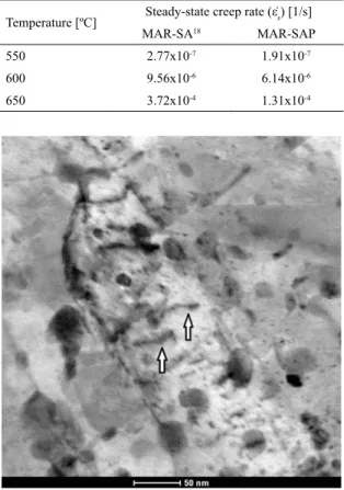
The analysis of the values of the activation energy and stress exponent suggests that the creep mechanism is associated with dislocation climbing process23,24. Figure 8 shows TEM image of the crept samples at 650 ºC and 500 MPa. The micrograph depicts dislocation cell structures.
Figure 6: Dependence of steady-state rate on applied stress at 650 ºC for MAR-SA18 and MAR-SAP (the slope is n).
Figure 7: Dependence of steady-state rate on temperature at 500
MPa for MAR-SA18 and MAR-SAP (the slope is –Q
c/R).
Figure 8: TEM bright ield micrograph of MAR-SAP crept at 650
ºC and 500 MPa showing dislocations.
3.3. Characteristics of fracture surfaces
Both the MAR-SA18 and the MAR-SAP samples
showed a cup-and-cone fracture morphology after creep
tests, characteristic of a ductile type of failure. Figure 9a is a representative SEM micrograph showing the general view
of the fracture surface of the MAR-SA sample crept at 650 ºC and 300 MPa, consisting of dimpled rupture surrounded by shear lips. Figure 9b is a higher magniication image of
the equiaxed dimples at the location enclosed in Figure 9a.
Otherwise, from Table 2 it can be noticed that the ductility (elongation, %) decreased after plasma nitriding,
considering all stress conditions of creep tests. The ductility
of the SAP are 17 to 40% lower than that of
MAR-SA samples. Ductility reduction of nitrided sample is also observed by fractographic analysis.
The fracture surface of MAR-SAP crept at 650 ºC and
300 MPa is illustrated in Figure 10a, showing a dimpled rupture region at the center surrounded by shear lips and encircled by a narrow rim. Equiaxed dimples were observed in the dimpled region in the center part of fracture surface,
Figure 9: Secondary electron SEM images showing the fracture morphology of the MAR-SA crept at 650 ºC and 300 MPa. (a) The dimpled rupture surrounded by shear lips (characteristic of ductile fracture). (b) Equiaxed
dimples at the location enclosed in Fig. 9a.
Figure 10: Secondary electron SEM images showing the fracture surface of the MAR-SAP crept at
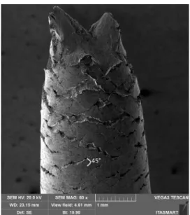
Figure 11: Secondary electron SEM image showing the circumferential
cracks on the surface of plasma nitrided alloy crept at 650 ºC and 300 MPa with cracks perpendicular and cross-linked at a 45º angle
relative to the tensile loading direction.
proile (Figure 3). It can be associated to the iron nitrides
formed and nitrogen solution hardening regions after plasma
nitriding. Microcracks initiating from the surface were
observed near the surface as shown in Figure 10d. The higher
ductility of MAR-SA compared to MAR-SAP could also
be inferred from top view of Fig 9a and 10a respectively.
The ibrous fracture area of MAR-SA is 35% smaller than that of MAR-SAP indicating higher ductility for the irst.
Figure 11 is a side view SEM image of MAR-SAP
sample after rupture showing the formation of circumferential
(transverse) microcracks on the nitrided surface perpendicular and cross-linked at 45º angle relative to the tensile loading
direction.
Creep fracture has been described by the phenomenological Monkman-Grant relationship25, which states that the fracture
of creep-deforming material is controlled by the steady-state
creep rate according Equation 2:
( )
t
r SC
2
M
f
o
=
Q V
Where M is a constant typically about 1.0 (when following
the Monkman-Grant relationship) and C is referred to as
Monkman-Grant constant. However the value of C is material dependent, the values normally observed is in the range of 0.001 to 0.1. As a general rule, larger C values tend to be recorded for materials displaying higher creep ductility23.
Figure 12 shows the Monkman-Grant correlation of MAR-SA and MAR-SAP. For both cases, M is around 1.0 (MAR-SAM
= 1.017 and MAR-SAPM = 0.968), independent of creep
testing temperature and stress regime. This indicates that the creep rupture of the 300 grade maraging steel nitrided
and un-nitrided follow the Monkman-Grant relationship for
Figure 12: Correlation between steady-state creep rate (ε̇s) and time
to fracture (tr) for MAR-SA
18 and MAR-SAP from 550 to 650 ºC.
the stress and temperature studied. Monkman-Grant constant C is smaller in the MAR-SAP (C = 0.0270) compared with MAR-SA18 (C = 0.0683), which result from the reduction of creep ductility after plasma nitriding.
Therefore, ductility measurement, fractography and
Monkman-Grant relationship show a reduction of ductility and cracks propagation in the surface in the MAR-SAP when compared to MAR-SA18. During the plasma nitriding, nitrogen
atoms are difused into the surface and near-surface regions.
Because the atoms occupy space in the lattice, they tend to produce compressive residual stress parallel to the surface that
can be used to neutralize, or counteract, potentially damage
tensile applied stress26. Therefore, the compressive residual
stress on the nitrided layer of MAR-SAP sample act as a barrier
to the elongation reducing the ductility when compared to
un-nitrided samples. Once the tensile stress during the creep test overcomes the compressive residual stress, the cracks
in the surface start to propagate, and the plastic deformation will concentrate in this region. The higher RMS roughness
showed in Figure 4 by MAR-SAP sample indicates the
higher roughness of the nitrided layer and may contribute to
the presence of stress concentrators on the layer’s surface to initiate the crack. Although this characteristic is negative to the creep resistance, the positive efect of oxidation barrier
from the nitrided layer compensates the ductility loss, and the overall creep resistance is improved at the end.
4. Conclusions
The following concluding remarks could be drawn based on plasma nitrided and un-nitrided 300 grade maraging steel:
• An uniform 50 μm thick surface layer of ε-Fe3N
and γ’-Fe4N was formed, increasing the surface microhardness from 604 ± 18 HV to 1,140 ± 15 HV and RMS roughness in the nanometric scale from
52 nm to 71 nm, respectively for un-nitreded an
presence of two regions: one where the nitride phases are predominant and other with solution hardening
by nitrogen atoms. The un-nitrided core remained un-altered, showing the typical hardness value and plate-like martensite microstructure;
• Typical creep curves consisting of well-deined primary, secondary and tertiary stages were found.
Creep resistance of nitrided samples improved from 52-65% when compared to un-nitrided samples,
and it seems to be associated with the continuous
layer of iron nitrides that behave as a difusion barrier for inward oxygen difusion into the alloy
reducing the oxidation rate.
• Based on the stress exponent (n), activation energy for
creep (Qc) and heterogeneous dislocation structure, it is concluded that the dominant creep mechanism is primarily controlled by dislocation climb. • Dominant type of failure was ductile showing a
typical cup-and-cone fracture morphology, consisting of equiaxed and bi-modal dimples in the ibrous zone surrounded by 45º shear lip. The ductility of the nitrided samples are 17-40% lower, conirmed by Monkman-Grant relationship and fractographic
analysis, and it is associated to the hard surface layer.
5. Acknowledgements
The authors are grateful to CNPq [grant numbers 141274/2013-1 and 403070/2016-3], CAPES [grant number Projec Pro-Defesa 014/08], LCS/LNNano/CNPEM (AFM), FAPESP and FINEP-PROINFRA. Thank is also to Prof. Carlos de Moura Neto (in memoriam).
6. References
1. Pereloma E, Edmonds DV, eds. Phase transformations in steels:
Difusionless transformations, high strength steels, modelling and
advanced analytical techniques. 1st ed. Cambridge: Woodhead
Publishing Limited; 2012.
2. Sha W, Guo Z. Maraging Steels: Modelling of Microstructure, Properties and Applications. Boca Raton: Woodhead Publishing
Limited; 2009.
3. Hall AM, Slunder CJ. The metallurgy, behavior, and application of the 18-percent Nickel Maraging steels: A survey. Washington:
Technology Utilization Division, National Aeronautics and
Space Administration; 1968.
4. Schmidt M, Rohrbach K. Heat treating of Maraging Steels. In:
ASM Handbook Committee. ASM Handbook: Heat treating.
Volume 4. Materials Park: ASM International: 1991. p. 528-548. 5. Greyling CJ, Kotzé IA, Viljoen PE. The kinetics of oxide ilm
growth on maraging steel as described by space-charge efects.
Surface and Interface Analysis. 1990;16(1-12):293-298.
6. Abe F, Kern TU, Viswanathan R. Creep-resistant steels. 1ts ed. Cambridge: Woodhead Publishing; 2008.
7. Oliveira AC, Oliveira RM, Reis DAP, Carreri FC. Efect of
nitrogen high temperature plasma based ion implantation on
the creep behavior of Ti-6Al-4V alloy. Applied Surface Science.
2014;311:239-244.
8. Reis AG, Reis DAP, Moura Neto C, Barboza MJR, Oñoro J.
Creep behavior and surface characterization of a laser surface nitrided Ti-6Al-4V alloy. Materials Science and Engineering A. 2013;577:48-53.
9. Swindeman RW, Douglas DA. Improvement of the high-temperature
strength properties of reactor materials after fabrication. Journal of Nuclear Materials. 1959;1(1):49-57.
10. Issartel C, Buscail H, Caudron E, Cuef R, Rifard F, Perrier S, et al. Inluence of nitridation on the oxidation of a 304 steel at 800 ºC. Corrosion Science. 2004;46(9):2191-2201.
11. Reis AG, Reis DAP, Abdalla AJ, Otubo J, Zepka S, Couto AA, et al. Efect of Simultaneous Plasma Nitriding and Aging
Treatment on the Microstructure and Hardness of Maraging 300 Steel. In: Öchsner A, Altenbach H, eds. Advanced Structured Materials. Volume 70 - Mechanical and Materials Engineering of Modern Structure and Component Design. New York: Springer
International Publishing; 2015. p. 277-284.
12. Yan MF, Wu YQ, Liu RL. Plasticity and ab initio characterizations
on Fe4N produced on the surface of nanocrystallized 18Ni-maraging steel plasma nitrided at lower temperature. Applied Surface Science. 2009;255(21):8902-8906.
13. Fernándes de Ara J, Almandoz E, Palacio JF, Fuentes GG, Rodríguez RJ, García JA. Inluence of temperature in arc-activated
plasma nitriding of maraging steel in solution annealed and aged conditions. Surface and Coatings Technology. 2014;258:754-762.
14. Shetty K, Kumar S, Raghothama Rao P. Efect of ion nitriding on the microstructure and properties of maraging steel (250 Grade).
Surface and Coatings Technology. 2009;203(10-11):1530-1536.
15. Viswanathan UK, Kutty TRG, Keswani R, Ganguly C. Evaluation
of hot hardness and creep of a 350 grade commercial maraging steel. Journal of Materials Science. 1996;31(10):2705-2709.
16. Gurewitz G, Atzmon N, Rosen A. Creep and stress relaxation in 18% Ni (250) maraging steel. Metals Technology. 1977;4(1):62-65.
17. Campbell JE, Barone FJ, Moon DP. The mechanical properties of the 18 per cent nickel maraging steels. Columbus: Defense
Metals Information Center - Battelle Memorial Institute; 1964. 18. Reis AG, Reis DAP, Abdalla AJ, Otubo J. High-temperature creep
resistance and efects on the austenite reversion and precipitation of 18 Ni (300) maraging steel. Materials Characterization.
2015;107:350-357.
19. American Society for Testing and Materials (ASTM). ASTM E139-11.Standard Test Methods for Conducting Creep, Creep-Rupture, and Stress-Rupture Tests of Metallic Materials. West
Conshohocken: ASTM International; 2011. 14 p.
20. Carvalho LG, Andrade MS, Plaut RL, Souza FM, Padilha AF.
A Dilatometric study of the phase transformations in 300 and 350 maraging steels during continuous heating rates. Materials Research. 2013;16(4):740-744.
21. Reis AG, Reis DAP, Abdalla AJ, Otubo J, Sandim HRZA. A