Abstract
A novel ship concept design is significantly an “adhoc” process. In the preliminary design stage of novel vessels, it is very important to be able to develop an initial estimate of the effects of stiffness and mass distribution on the longitudinal flexural natural frequencies due to different general arrangements in still water at zero speed to satisfy design specifications. For new emerging designs, this estimate has to be made based on a model test. The experiments should also be planned so that scales effects and other features that are not present in full scale case, are minimized. A model with a length of 1.5 meter has been selected. The model was cut into four segments longitudinally and connected by a backbone beam with three elastic hinges joining the four segments. Wet vibration tests were conduct-ed on the model, showconduct-ed significant influences on the flexural natu-ral frequencies through variations in stiffness and different mass distributions. The whipping frequency was calculated with four degrees of freedom theoretical model to compare with the experi-mental results. The theoretical model shows a good agreement with the experimental results.
Keywords
Novel Trimaran; segmented model; elastic hinge; natural frequen-cy; model test.
Analysis of the flexural mode response of a novel trimaran by
segmented model test
1 INTRODUCTION
Marine vehicles with speeds above 30-35 knots which have recently been used primarily for both passenger transport and military applications are limited to high-speed monohulls and Multihulls. High forward speeds, complex structural outlines and the use of novel materials make the analysis of these vessels more challenging than conventional ships. During the last few years, there has been an increasing interest in the application of high speed multihull ships for military applications. When the high speed vessel concepts are up scaled, some new problems arise. The global hydrody-namic loads depend both on the ship’s rigid body motions and its elastic deformation. These
hydro-Karim Akbari Vakilabadia Mohammad Reza Khedmatib Habiballah Sayyaric
a,bDepartment of Marine Technology,
Amirkabir University of Technology, Tehran, Iran
cSupreme National Defense University, Tehran, Iran
bCorresponding author: [email protected]
Latin American Journal of Solids and Structures 11 (2014) 2573-2588
elastic effects can be of particular importance for large high speed vessels. Springing is one of the challenges in ship-shape vessels. High speed and low rigidity are two features of a ship which gener-ally increase the springing problems. The springing phenomenon may not influence the extreme structural responses, but the fatigue damage could be significantly increased (Friis-Hansen et al., 1995).
Hydroelasticity can be significant not only for steady state responces but also for those of the transient type. The flexibility of the structure in the area of slamming impact can influence the total slamming load (Kvalsvold, 1994), and the overall stiffness of the vessel’s structure is important for global (whipping) responses. Ship classification societies have traditionally predicted the struc-tural loads of ships using an empirical approach based on experience with previous vessels in con-trast to an experimental analysis of the wave induced loads, Thomas et al. (2003a). Segmented monohull models have been traditionally developed to measure motions and loads at low Froude numbers as the work reported by Gerritsma et al. (1964) and Lloyd et al. (1979). This was followed by the evolution of low Froude number hydroelastic segmented models designed to replicate the whipping response of a full-scale vessel in addition to measuring motions and loads for the valida-tion of numerical simulavalida-tions, McTaggart et al. (1997). Dessi et al. (2005) have developed an elas-tically scaled high-speed monohull model used to measure dynamic loads and to replicate the modal response of the full-scale vessel with experimental results showing good correlation with finite ele-ment theory for dry tests in air. Kapsenberg et al. (2003) investigated a similar monohull model with an emphasis on slam loads and mathematically simulating whipping responses. Despite the extensive works have been conducted on the prediction and measurement of dry modal frequencies there is a lack of knowledge in validation of the theoretical wet modal frequency with the experi-mental wet modal frequency.
The model should be as simple as possible in order to provide easy and accurate measurements, and to keep production costs and time within reasonable limits. At the same time it should be suffi-ciently realistic for final calculations to be of practical values. Similarly, the model should be flexible enough to produce easily measurable hydroelastic responses, but not so flexible that qualitatively unrealistic phenomena occur. As discussed by Maeda (1991), flexible ship models can be constructed by different principles. The seakeeping Committee of 17th ITTC (ITTC 1984) also discusses various aspects of flexible model tests. A logical approach is to make the model continuously elastic (Watanabe et al., 1988). By this approach the stiffness distribution resembles a real ship, but it is difficult to adjust the stiffness once the model was produced. Alternatively, one can divide the ship hull into segments and connect the segments with a beam, or backbone, that has the proper stiff-ness. The backbone could be continuously elastic (Riska, 1994), or it could consist of stiff parts that are connected by elastic hinges (Troesch, 1984). Wereldsma (1974) has also proposed to use a com-pletely stiff backbone. In the present experiments a novel wave piercer bow trimaran was utilized. The model was originially completely rigid, and the only practical way of making it flexible was to cut it into three segments. A rigid backbone frame with three elastic hinges was selected. According to variety of mass distribution due to different general arrangement, the vessels flexibility could be adjusted by changing the hinge geometry.
Latin American Journal of Solids and Structures 11 (2014) 2573-2588 predict the wet modal frequency which is validated with experiments. The effect of model stiffness and an weight distributionon the measured flexural response has been studied. A theoretical model of a four degree of freedom system using an theoretical hydrodynamic added mass was developed to predict the wet modal frequency of the model as a function of stiffness and mass distributions.
2 SELECTION OF MODEL WEIGHT DISTRIBUTIONS BASED ON A PROTOTYPE VESSEL
Light warships are typical of volume-limited ships and it is these types which are most suited to the wider and more convenient deck spaces above the waterline that the multihull offers. A more com-plex investigation into the choice of hullform must be based on the required attributes of the ship, such as arrangement, speed and seakeeping. Multihulls provide a good and useful deck layout with a greater deck area per ton of displacement compared to monohulls. Arrangement is a crucial pa-rameter that affectes the weight distribution in the model test.
Estimation and prediction of weight distribution is an essential task in the design phase of a vessel, and the accuracy of this work will be crucial for the success of the project. Weight distribu-tion is based on required general arrangement according to vessel missions. Predicdistribu-tion-based design uses a set of user specifications for a certain class of ships to predict the rest of the weight distribu-tion parameters. The predicdistribu-tion of ship weight distribudistribu-tion is performed with an statistical method and international classification rules.
In the early stages of designing new ships it is necessary to estimate the weight per unit length of the vessel to predict the initial weight and cost. One of the most important issues for design of military vessels is a number of equipment, structural integrity, navigation facilities, armament and etc. Novel vessels have to be designed considering the limitations caused by these design require-ments. For select the several logical general arrangement, shall be provide some class specific data for vessels. Table 1 give detailed The Weight Distribution for some selected Navy ship classes are presented in Table 1.
Table 2 presents the technical specification of the model which is based on the weight distribu-tion presented in table 1. The ship to model scale ratio was 80 which is suitable for the size of the towing tank facility. Three weight distributions based on various general arrangements were consid-ered in this experiment. Ship Model is divided in 20 stations longitudinally and each permanent segment weight is calculated.
3 THEORETICAL BACKGROUND
Latin American Journal of Solids and Structures 11 (2014) 2573-2588 Weight segment
STN-STN
Weight Per Segment, lton
DD963V DD963N DD993 FF1052 FFG7
FWD-0 0 0 0 10.25 19.4
0-1 292.63 313.95 341.12 120.81 41.6
1-2 150.77 155.11 176.87 227.12 84.2
2-3 177.06 200.28 215.29 145.32 108.3 3-4 296.62 211.84 259.47 114.63 201.6
4-5 495.39 373.8 468.52 110.53 217.6
5-6 356.95 371.98 386.21 281.63 266.3 6-7 554.18 566.12 577.06 277.84 273.2 7-8 689.09 697.38 753.01 361.94 109.6 8-9 603.53 609.35 651.18 198.94 189.9 9-10 697.34 728.05 693.78 270.45 268.2 10-11 581.52 580.02 689.04 283.75 273.2
11-12 706.47 712.6 875.02 268.35 246
12-13 619.19 571.36 643.72 218.46 220.2 13-14 440.53 445.46 487.83 287.16 302.2 14-15 443.78 367.78 551.32 209.86 250.6 15-16 421.31 296.79 495.89 239.97 184.6 16-17 388.4 360.19 481.8 171.87 207.6 17-18 313.36 293.75 414.81 162.17 101.8 18-19 364.79 342.27 366.42 144.98 162.3 19-20 302.46 276.95 258.06 147.98 120.2
20-AFT 0 0.03 0 0 25.4
SUM 8895.37 8475.06 9786.42 4254.01 3874
Table 1: Weight Distribution for selected ship clases (US Navy Direction Of Commander, 2000).
Particular Prototype [m] Model (1/80) [m]
Length overall 124 1.55
Length at waterline 123.2 1.54
Beam overall 21.776 27.22x10⁻²
Beam at waterline 9.6 12x10-2
Depth 11.776 14.72x10⁻²
Draught 4.384 5.48x10⁻²
Length of side hull 36 45x10-2
Beam of side hull 2.36 2.95x10⁻²
Depth of side hull 8.136 10.17x10⁻²
Draft of side hull 74.4 0.93x10⁻²
Clearance between centerline of main and side hull 9.7 12.125x10⁻²
Displacement 2248.81Tonne 4.39x10⁻³
Latin American Journal of Solids and Structures 11 (2014) 2573-2588 f m f m l w w l = where m
w = model scale modal frequency, wf= full-scale modal frequency, lf = full-scale length of vessel,
m
l = model scale length. It is therefore possible to achieve the whipping frequency at model scale by scaling the full-scale frequency and designing the model with the capability of achieving a modal response that replicates the flexural dynamics of the full-scale vessel. Although the segmented model concept is an approximation of the full-scale vessel structural response, it facilitates a practical sim-ulation of the whipping phenomena observed on a full-scale vessel.
A four degree of freedom theoretical model was developed in order to predict the longitudinal bending frequency of the model as a function of the effective stiffness and mass distribution of the model. Figure 1 shows the four degree of freedom model consists of a four rigid hull segments which are connected by three elastic hinges. The aft segment consists of aft main hull part and side hulls.
Figure 1: Four degrees of freedom system representing the segments of hull joined together with elastic hinges.
Let:
rotation of hull segment q
centre of mass of segment-1 C1
total mass m
centre of mass of segment-2 C2
mass of segment 1 1
m centre of mass of segment-3
C3
mass of segment 2 2
m centre of mass of segment-4
C4
mass of segment 3 3
m distance from K1 to centre of mass of segment-1
1
X
mass of segment 4 4
m distance from K1 to centre of mass of segment-2
2
X
stiffness of torsion spring-1 1
K distance from K2 to centre of mass of segment-2
3
X
stiffness of torsion spring-2 2
K distance from K2 to centre of mass of segment-3 4
X
stiffness of torsion spring-3 3
K distance from K3 to centre of mass of segment-3
5
X
shear force V
distance from K3 to centre of mass of segment-4
6
X
moment of inertia of segment-2 2
I moment of inertia of segment-1
1
I
moment of inertia of segment-4 4
I moment of inertia of segment-3
3
I
vertical displacement y
Latin American Journal of Solids and Structures 11 (2014) 2573-2588
(
)
1 1 1 2 2 3 2 4 3 1
m y+xq +x q +x q +x q = -V (1)
(
)
2 3 2 4 3 1 2
m y+x q +x q =V -V (2)
3 2 3
m y=V -V (3)
(
)
4 6 4 5 3 3
m y-x q -x q =V (4)
(
)
1 1 1 1 2 1 1
V x -K q -q =I q (5)
(
)
(
)
1 1 2 2 2 3 1 2 2 3 2 2
K q -q -K q - q +V x +V x =I q (6)
(
)
(
)
2 2 3 3 3 4 2 4 3 5 3 3
K q -q -K q -q +V x +V x =I q (7)
(
)
3 6 3 4 3 4 4
V x -K q -q =I q (8)
By substituting equation (1) in equation (2) we get V2,
(
)
(
)
2 1 1 1 2 2 3 2 4 3 2 3 2 4 3
V =m y+x q -x q +x q +x q -m y+x q -x q (9)
Then:
(
)
(
)
1 1 1 1 2 1 3 2 3 2 1 4 2 4 4 5 3 4 6 4
m x m x m x m x m x m x m x m x
y
m
q q q q
- - + + - + - +
=
By substituting equation (4) and equation (9) in equation (3) y is obtained and by Eliminating y from (6), (7) and (8) and
(
)
4 4 2 4 4 5 1 4
1 1 4 1 1 4 1 1 3
1 2 1 3 2 3 1 1
1 1 1 1 3 1 1 2 2 1 1 1 1 1 1 1 1 1 2 0
m x m x m x m x
m x m x x m x
m m
m x m x m x m x
m x m x x m x x m x m x x I K
m m
q q
q q q q
æ ö÷ æ - - ö÷
ç- ÷ + -ç - ÷
ç ÷ ç ÷
ç ÷ ç ÷
ç ç
è ø è ø
æ - - ö÷ æ ö÷
ç ÷ ç ÷
+ -ççç - + ÷÷ +ççç - - ÷÷ - - =
è ø è ø
(10)
4 4 2 4 4 5 1 4 1 2 1 3 2 3 1 1
1 2 4 3 2 1 1 1 2 2 3 2 4 3
4 4 2 4 4 5 1 4 1 2 1 3 2 3 1 1
1 3 4 3 2 1 1 1 2 2 3 2 4 3
m x m x m x m x m x m x m x m x
m x x x x x
m m m m
m x m x m x m x m x m x m x m x
m x x x x x
m m m m
q q q q q q q q
q q q q q q q q
æ - - - - ö÷
ç ÷
- çç + + - + - + + ÷÷
çè ø
æ - - -
-ç
- ç + + - + - + +
è
(
)
(
)
4 4 2 4 4 5 1 4 1 2 1 3 2 3 1 1
2 3 4 3 2 1 3 2 4 3
1 1 2 — 2 2 3 2 2
m x m x m x m x m x m x m x m x
m x x x
m m m m
K K I
q q q q q q
q q q q q
ö÷÷ ÷
ç ÷
ç ø
æ - - - - ö÷
ç ÷
- çç + + - + - ÷÷
çè ø
+ - - =
(11)
4 4 4 4 4 4 2 4 4 5 1 4
1 4 2 4 4 5 4 5 6 4 3 1 4 1 4 4
2 4 4 5 1 4 2 4 4 5 1 4 1 2 1 3 2 3
2 4 2 4 4 4 5 4 5 5 3 1 4
1 4 2 1 4 3 2 4
m x m x m x m x m x m x
m x m x m x m x x I m x m x x
m m m m
m x m x m x m x m x m x m x m x m x
m x m x x m x m x x m x
m m m
m x x m x x m x
q
q
æ ö÷ æ
ç ÷ +ç
ç ÷ ç
ç ÷ ç
ç ç
è ø è
ö æ
÷ ç
÷ + ç
÷ ç ÷ - -- - + - - - -- - - -- + + + -+ ç ø è - - ( ) ( )
1 2 1 3 2 3 1 2 1 3 2 3 1 1
2 4 3 4 5 2 1 4
1 1 1 1
1 4 1 2 4 4 5 1 2 2 3 3 4 3 0
m x m x m x m x m x m x m x
m x x m x m x
m m m
m x m x
m x x m x m x K K
m m
q
q q q q q
ö æ
÷ ç
÷ + ç
Latin American Journal of Solids and Structures 11 (2014) 2573-2588
(
)
4 4 2 4 4 5 1 4
4 4 6 4 6 6 4 4 6 4 6 5 3
1 2 1 3 2 3 1 1
4 6 2 4 6 1 3 4 3 0
m x m x m x m x
I m x m x x m x m x x
m m
m x m x m x m x
m x m x K
m m
q q
q q q q
æ ö÷ æ - - ö÷
ç- + - ÷ +ç + ÷
ç ÷ ç ÷
ç ÷ ç ÷
ç ç
è ø è ø
æ - - ö÷ æ ö÷
ç ÷ ç ÷
+çç ÷÷ + -çç ÷÷ - - =
ç ç
è ø è ø
(13)
Considering 2
i n i
q = -w q results with the formulation of the following matrix
11 12 13 14 1
21 22 23 24 2
31 32 33 34 3
41 42 43 44 4
0
a a a a
a a a a
a a a a
a a a a
q q q q
é ù é ù
ê ú ê ú
ê ú ê ú
ê ú ê ú =
ê ú ê ú
ê ú ê ú
ê ú ê ú
ê ú ê ú
ë û ë û
(14)
where
n
w : natural frequency
1 1 2
11 1 1 1 1 1 1 n 1
m x
a m x m x x I K
m w
æ ö÷
ç ÷
= -çç + + ÷÷
-çè ø
1 2 1 3 2 3 2
12 1 1 1 1 3 1 1 2 1
2 4 4 5 1 4 2
13 1 1 4 1 1
4 4 2
14 1 1
21 12 31 13 41 14 n n n
m x m x m x
a m x m x x m x x K
m
m x m x m x
a m x x m x
m m x
a m x
m a a a a a a w w w
æ - - ö÷
ç ÷
=çç + - ÷÷ +
çè ø
æ - - ö÷
ç ÷
=çç + ÷÷
çè ø
æ ö÷
ç ÷
= çç ÷÷
çè ø
= = =
1 2 1 3 2 3 1 2 1 3 2 3
22 2 1 2 1 2 3 1 2 2 1 3
1 2 1 3 2 3 2
1 3 3 1 3 2 2 3 2 3 3 1 2
( )
( )
( )
n
m x m x m x m x m x m x
a I m x m x x m x x m x
m m
m x m x m x
m x x m x x m x m x x K K
m w æ ö÷ ç ÷ ç ÷ ç ÷ çè ø
é - - -
-ê
= ê + + - +
ë
ù
- - ú
+ - + + ú - +
û
2 4 4 5 1 4 2 4 4 5 1 4
23 1 2 4 1 2 1 3
2 4 4 5 1 4 2
1 3 4 2 3 2 3 4 2
( ) ( )
( )
n
m x m x m x m x m x m x
a m x x m x m x
m m
m x m x m x
m x x m x m x x K
m w
é - - -
-ê
= ê + +
ë
ù
- - ú
+ + - ú +
û
4 4 4 4 4 4 2
24 1 2 1 3 2 3
32 23
42 24
n
m x m x m x
a m x m x m x
m m m
a a
a a
w
æ ö÷
ç ÷
=çç + + ÷÷
çè ø
Latin American Journal of Solids and Structures 11 (2014) 2573-2588
2 4 4 5 1 4 2 4 4 5 1 4
33 3 1 4 1 4 4 2 4
2 4 4 5 1 4 2
2 4 4 4 5 4 5 5 2 3
( ) ( )
( )
( )
n
m x m x m x m x m x m x
a I m x m x x m x
m m
m x m x m x
m x x m x m x x K K
m w
é - - -
-ê
= ê + + +
ë
ù
- - ú
- - - ú - +
û
4 4 4 4 4 4 2
34 1 4 2 4 4 5 4 5 6 3
43 34
4 4 2
44 4 4 6 4 6 6 3
n
n
m x m x m x
a m x m x m x m x x K
m m m
a a
m x
a I m x m x x K
m
w
w
æ ö÷
ç ÷
=çç + - + ÷÷ +
çè ø
=
æ ö÷
ç ÷
=çç - + ÷÷
-çè ø
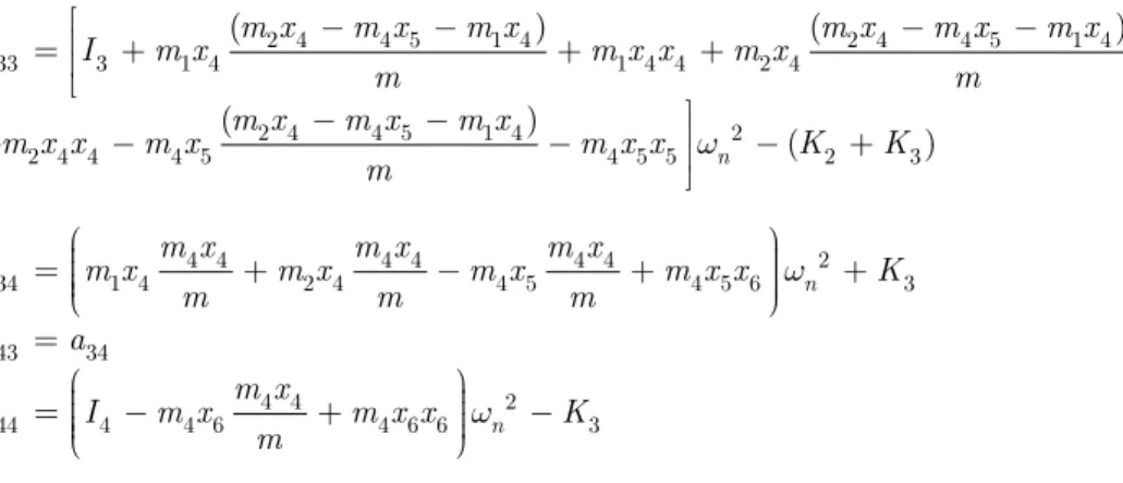
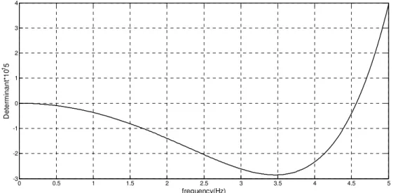
Evaluating the determinant of the matrix defined in equation 14 and excluding the solution at zero frequency for rigid body motion leads to the theoretical values of the natural frequencies of the four degree of freedom mass-spring system for which the determinant is zero. Table 3 shows a summary of the parameters that were input to the theoretical model and Figure 2 shows the results of the matrix determinant as a function of frequency for the evaluation of the wet modal frequency response of the hydroelastic segmented ship model.
Variable Length(mm) Variable Value Variable Value
1
x 260 m1 1000 gr K3 3000 N/m
2
x 120 m2 1000 gr I1 0.35 Kg.m2
3
x 130 m3 1350 gr I2 0.1 Kg.m2
4
x 160 m4 1000 gr I3 0.5 Kg.m2
5
x 140 K1 3000 N/m I4 0.3 Kg.m2
6
x 140 K2 3000 N/m
Table 3:Summary of the input physical parameters to the four degrees of freedom theoretical model.
( )
9(
8 6 4 5 2)
det A = 10 4.152w +616w +3200w -3.72´10 w (15)
8 6 4 5 2
4.152w +616w +3200w -3.72´10 w =0 (16)
It is observed from the results shown in Figure 2 that the wet modal frequency of the four de-gree of freedom system is 0 Hz for rigid body motion, 4.61Hz for the first longitudinal mode. Figure 3 shows the model first longitudinal mode shape calculated for natural frequency.
4 MODEL DESCRIPTION
4.1 Hull Shape
Latin American Journal of Solids and Structures 11 (2014) 2573-2588 Figure 2: Matrix determinant of the four degrees of freedom mass-spring system for the theoretical evaluation of
the wet flexural response frequency of the 1.5m test model based on the input parameters summarised in table 3.
Figure 3: Hydroelastic segmented model normalised mode shape in still water and at zero speed at a natural ben-ding frequency of 4.61Hz.
4.2 Stiffness distribution
The backbone frame is very stiff and the elastic hinges are located close to the gaps between the hull segments. There are three cut along the model length; one at the 0.25Lpp from FORE perpen-dicular, one at the midship and another at position of outriggers connect to main hull.
0 0.5 1 1.5 2 2.5 3 3.5 4 4.5 5
-3 -2 -1 0 1 2 3 4
frequency(Hz)
D
et
er
m
inant
*10
15
0 10 20 30 40 50 60 70 80 90 100
-1.5 -1 -0.5 0 0.5 1 1.5
Distance from stern(m)
N
o
rm
alized
m
o
d
e
sh
ap
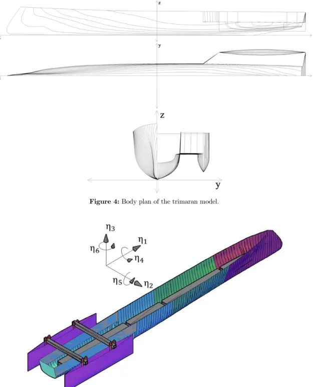
Latin American Journal of Solids and Structures 11 (2014) 2573-2588 Figure 4: Body plan of the trimaran model.
Figure 5: Outline of the trimaran model.
4.3 Mass Distribution
Latin American Journal of Solids and Structures 11 (2014) 2573-2588 surface when the ship is at rest at zero speed. Main contributions to the model’s mass come from the hulls, which are made of fiber glass resin and backbone frame which is made of aluminum. The hull was cut longitudinally into three sections. Each rigid segment was attached to an aluminium square hollow section backbone beam. The segments of the model were joined together with three flexible elastic hinges that are interchangeable in order to vary the stiffness of the links. Separating the model into segregated compartments allowed the position and magnitude of ballast mass to be systematically located within the model to vary the configuration of ballast mass distribution ac-cording to three different general arrangements.
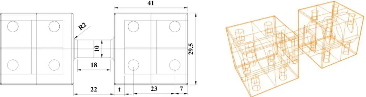
A schematic diagram of the elastic hinge is shown in Figure 6. The elastic hinge consists of a square hollow plug on either end that was connected at the center by a flexible link of square cross section. Either end of the elastic hinge was inserted into the aluminum SHS (32x32x1.5) beam and was joined together with bolts to produce a highly rigid connection. The cross section dimensions and length of the flexible link were varied in order to adjust the stiffness and flexibility of the con-nection. Aluminum alloy was selected as the most suitable material for the manufacture of the elas-tic hinges as it was sufficiently light and was found to provide adequate strength and stiffness. The elastic hinges were manufactured on a CNC programmable machine at the Amirkabir University of Technology.
Figure 6: Elastic hinge built for the measurement of wave induced strains and the adjustment of stiffness.
Experimental bending tests were performed on a sample of elastic hinges with different wall thickness t, in order to investigate the effect of wall thickness and weight on the ultimate strength and stiffness. Four elastic hinge samples were manufactured with a design stiffness of 3000 Nm/rad and wall thickness t, of 4 mm, 8 mm, 12 mm and 15 mm. The end plug of each elastic hinge was
fixed to a suitable mechanism in a cantilever arrangement. Experiment performed with compression testing machine and the loads were incremented until such stage the failure load and failure mecha-nism was physically identified (Figure 7).
With reference to Figure 8 it is obvious that increases in the wall thickness responded with in-creases in the ultimate strength of the elastic hinge. Physical experiments were therefore undertaken in order to identify the effects of wall thickness on the stiffness of the elastic hinge.
4.4 Data Acquisition
Latin American Journal of Solids and Structures 11 (2014) 2573-2588 Figure 7: Elastic hinge bending test by compression machine.
Figure 8: Deflections as a function of load for tests undertaken on the elastic hinges at a wall thickness of 4, 8, 12 and 15 mm.
5 TEST PROGRAM
5.1 Tests in air
Latin American Journal of Solids and Structures 11 (2014) 2573-2588 one at the midpoint of each segment, and vibrations were excited by giving it manual impulse force. Impulse force in different longitudinal locations will excite different mode shapes. Estimates of the damping levels and the eigen-frequencies, as well as an overview of mode shapes, were obtained by analyzing the signals from the microstrain. Useful information was obtained for the First mode by this method. The two springs from which the model was suspended, have eigen-frequencies that much smaller than those of the model therefore their influence on the measured frequencies could be neglected.
5.2 Test in water
Experiments were performed at towing tank of Marine Engineering Research Center, Sharif Univer-sity of Technology. Towing Tank Particulars is presented in Table 4. Tests were undertaken in still water and at zero speed with the model unrestrained and free to respond with dominant motions in heave and pitch. An impulse load was applied by hand at the stern of the model in order to excite the longitudinal mode of vibration. The stern was selected as the most appropriate position as this produces the most reliable and reproducible signal response. Model accelerations were recorded us-ing an accelerometer that was located at the different position of the model (Figure 9).
Figure 9:Measurements of the model accelerations by Microstrain.
Towing System Maximum acceleration of
carriage Maximum Speed of
carriage Length×Width×Depth
of the tank
Electromotor (4 kW) 2 m/s2
6 m/s 25 × 2.5× 1.2 m
Table 4: Towing tank particulars.
elas-Latin American Journal of Solids and Structures 11 (2014) 2573-2588
tic hinge. It was observed that although the stiffness of the elastic hinge was increased the overall measured stiffness approached the stiffness of the hull. This was due to the inherent flexibility of the fibre glass hull and aluminium backbone beam causing significant bending between the mount-ing points across each segment of hull and is discussed in further detail by Jason Lavroff et al. (2006).
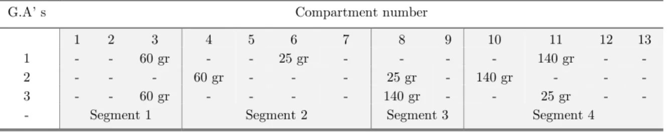
The modal frequency response of the model was also evaluated as a function of the ballast mass distribution. According to three different general arrangements, the ballast masses were located within the designated compartments of the model to produce three distinct mass distributions while maintaining a constant trim angle for each elastic hinge stiffness configuration. Essentially this ena-bled the variation of both the ballast mass distribution and the effective stiffness of the model in order to observe the effects on the whipping frequency response. Table 5 presents three general ar-rangement configurations implemented during trials conducted on the trimaran hydroelastic model.
G.A’ s Compartment number
1 2 3 4 5 6 7 8 9 10 11 12 13
1 - - 60 gr - - 25 gr - - - - 140 gr - -
2 - - - 60 gr - - - 25 gr - 140 gr - - -
3 - - 60 gr - - - - 140 gr - - 25 gr - -
- Segment 1 Segment 2 Segment 3 Segment 4
Table 5:Model mass distribution according to General Arrangement (G.A).
A series of tests in calm water at zero speed are conducted on a novel Trimaran vessel in order to predict its Flexural Mode Response. There were altogether 42 test conditions. A brief summary of the tests is presented in Table 6 and Figure 9 shows a sample test.
MicroStrain Positions General Arrangement
Pos5 Pos4
Pos3 Pos2
Pos1
√ √
√ √
√ GA1
√ √
√ √
√ GA2
√ √
√ √
√ GA3
Table 6: Testing matrix for Flexural Mode Response.
6 MODEL TEST RESULTS
The whipping response was clearly observed during all tests undertaken on the segmented model. Figure 10 displays a typical accelerometer response recorded on the trimaran model following an impulse load at the stern.
Latin American Journal of Solids and Structures 11 (2014) 2573-2588 Figure 10:Whipping accelerations recorded at mid-ship of the experimental model.
7 CONCLUSIONS
A design methodology was developed to investigate the modal frequency of a trimaran ship model through the adjustment of stiffness with an elastic hinge and variety of general arrangements. These findings formulate an effective mechanism for attaining the natural frequency response of a seg-mented model for the purpose of replicating the whipping response of a full-scale vessel subject to slamming. It was shown that the full-scale whipping frequency could be scaled down to a model scale and through the adjustment of the appropriate parameters the target whipping frequency may be achieved.
A theoretical model was developed based on a four degree of freedom mass-spring system repre-senting four rigid hull segments connected by a set of springs longitudinally. It was shown that the theoretical model gave accurate predictions of modal frequency when compared to experimental results based on the effective stiffness of the model. The validation of the theoretical model through experiments aids the on-going development of a future hydroelastic model. Because of the aft seg-ment configuration the measured experiseg-mental natural frequency is different from the theoretical one.
References
Dessi, D., Mariani, R., Coppottelli, G., Rimondi, M., (2005). Experimental identification of wet bending modes with segmented model tests. 8th International Conference on Fast Sea Transportation, FAST ’05.
Friis Hansen, P., Winterstein, S. R., (1995). Fatigue Damage in the Side Shells of Ships. Marine Structures Vol. 8: 631-555.
Gerritsma, J., Beukelman, W., (1964). The distribution of the hydrodynamic forces on a heaving and pitching shipmodel in still water. Fifth Symposium on naval hydrodynamics ship motions and drag reduction, 219–246. Kapsenberg, G.K., Van’t Veer, A.P., Hackett, J.P., Levadou, M.M.D., (2003). Aftbody Slamming and Whipping Loads. Transactions of the Society of Naval Architects and Marine Engineers 111: 213-231.
Latin American Journal of Solids and Structures 11 (2014) 2573-2588
Lavroff, J., Davis, M. R., Holloway, D. S., Thomas, G., (2006). Experimental Analysis of the Wet Flexural Mode Response of an NPL 6A Hydroelastic Segmented Model. 5th International Conference on High Performance Ma-rine Vehicles, 8-10 November.
Lloyd, A.R.J.M., Brown, J.C., Anslow, J.F.W., (1979). Motions and loads on Ship Models in Regular Oblique Waves. Transactions of the Royal Institution of Naval Architects 122: 21-43.
Maeda, H., (1991). Modelling Techniques for dynamics of ships. Phil, Trans. R. Soc. London A 334: 304-317. McTaggart, K., Datta, I., Stirling, A., Gibson, S., Glen, I., (1997). Motions and Loads of a Hydroelastic Frigate Model in Severe Seas. Transactions of the Society of Naval Architects and Marine Engineers 105: 427-453.
Riska, R., Kukkanen, T., (1994). Speed dependence of the natural modes of an elastically scaled ship model. hy-droelasticity in marine technology, Rotterdam, The Netherlands, 157-168.
Thomas, G., Davis, M.R., Holloway, D.S., Roberts T.J., (2003a). Transient Dynamic Slam Response of Large High-speed Catamarans., 7th International Conference on Fast Sea Transportation, FAST ‘03.
Thomas, G., Davis, M.R., Holloway, D.S., Roberts, T.J., (2003b). The whipping vibration of large high-speed catamarans. Transactions of the Royal Institution of Naval Architects 145 A4: 13-29.
Troesch, A. W., (1984). Wave-induced hull vibrations: an experimental and theoretical study. Journal of Ship Research 28(2): 141-150.
US Navy Direction Of Commander, Naval Sea Systems Command, (2000). US Navy Salvage Engineer's Hand-book, Volume 1. S0300-A8-Hbk-010.