INVESTIGATION OF REPEATABILITY OF DIGITAL
SURFACE MODEL OBTAINED FROM POINT CLOUDS IN A
CONCRETE ARCH DAM FOR MONITORING OF
DEFORMATIONS
Investigação referente à Repetibilidade do Modelo Digital de Superfície obtido a partir de Nuvens de Pontos numa Barragem Abóbada de Betão para a
Monitorização de Deformações
KUTALMIS GUMUS HALIL ERKAYA METIN SOYCAN
Yildiz Technical University Civil Engineering Faculty
Geomatic Engineering Esenler, Istanbul, 34220.
kgumus@yildiz.edu.tr, erkaya@yildiz.edu.tr, soycan@yildiz.edu.tr
ABSTRACT
conditions. Digital Surface Models reflecting dam surface have been created. Results obtained from surface model differences were examined using surface matching method.
Keywords: Terrestrial Laser Scanners; Deformation Measurements; Concrete Arch
Dams; Data Analysis; Point Cloud.
RESUMO
A aplicação dos Scanners Laser Terrestres/Digitalização (SLT) para a medição de deformações em barragens representa uma área ativa de estudo. Com o avanço das tecnologias modernas, a exatidão da medição melhorou muito graças aos desenvolvimentos na conceção dos scanners laser terrestres. Atualmente, esta tecnologia é utilizada em grandes e complexas estruturas de engenharia tais como as barragens. Embora, os SLT sejam uma tecnologia de custo elevado, são particularmente utilizados na monitorização de deformações de barragens, devido à velocidade na obtenção de centenas de pontos de dados, à capacidade para visualizar o objeto digitalizado e o seu ambiente com elevada exatidão e capacidade para medições de longo alcance. Com a finalidade de determinar o efeito das alterações dos níveis de um reservatório de água no corpo de uma barragem, os SLT são utilizados para tirar as medições das deformações em diferentes intervalos de tempo, quando o nível da água se encontra em níveis máximos, mínimos ou médios. Este documento apresenta uma visão geral da tecnologia de digitalização laser terrestre para a medição de deformações. A barragem situada em Antalya Oymapinar, na Turquia, foi utilizada para o estudo de caso. Foram realizadas quatro digitalizações diferentes nessa barragem, a fim de verificar a reprodutibilidade dos resultados dos SLT nos mesmos níveis de água e em condições idênticas. Os Modelos Digitais de Superfície que refletiram a superfície da barragem foram criados. Os resultados obtidos a partir das diferenças do modelo de superfície foram examinados utilizando o método de correspondência de superfície.
Palavras-chave: Scanner Laser Terrestre; Medições de Deformação; Barragem
Abóbada de Betão; Análises de Dados; Nuvens de Pontos.
1. INTRODUCTION
precautions, the structure or the object that causes the risk should be monitored persistently in specific cycles.
From the past to present, many studies were conducted on solution of problems in social environments and monitoring of engineering structures by using different geodesic and physical measurement methods (SCHROEDEL et al., 2002). There exists a vast literature on monitoring of structures and detection of deformations by using these measurement methods. Today, Terrestrial Laser Scanners are starting to emerge and they are rapidly developing for these types of applications. In order to analyze these studies, new and accurate data is needed. The data obtained from Terrestrial Laser Scanners match with the truth data. Three dimensional geometric and visual data is gathered rapidly with laser scanning systems. With TLS, it is possible to gather details on hard to reach, dangerous objects and environments in a single shot. Because of these properties, laser scanners are used for risk evaluation and analysis across different applications, in particular evaluation of deformations in structures (dams, bridges, etc.) caused in the long run by internal and external forces.
There are many references in the literature regarding TLS applications. A general overview on TLS is presented on Pfeifer and Lichti (2004), Fröhlich and Mettenleiter (2004). Lemmens (2004) compared TLS with different designs on various applications and Boehler et al. (2003) performed accuracy analysis on the data obtained from laser scanners. The study on Bitelli (2004), Hesse and Stramm (2004) examined deformations by direct comparison of numerical height models obtained by using different TLS campaigns. Schneider (2006) performed deformation analysis for a television tower by comparing different sets of data obtained on different epochs from considering mathematical surfaces related to measurement points. Guarnieri et al. (2006) presented multi sensor approaches for preserving cultural legacy using structural analysis. Alba et al. (2006) studied TLS for monitoring deformations on large concrete dams, accuracy of positioning and comparison on different scanning results. A three dimensional polynomial surface was applied to TLS point cloud for monitoring of a large dam. Another study on dams can be found in Rudig (2005). Gruen and Akca (2005) explained the surface matching method by using least squares method. Heine et al. (2007) presented a study on teaching TLS technology as a part of European Leonardo da Vinci project and detection of deformations on a hydroelectric central.
instead of deformation analysis by point-wise. Real surface models can be generated by using TLS data. Deformation of the whole surface can be determined by comparing two or more surface models generated at different times. Aim of this paper is to detect deformations by obtaining realistic dam body surface models and performing surface comparison. For this purpose, four different scannings, which were taken at the equivalent conditions and water levels at Antalya Oymapinar Dam at April of 2008 to verify replicability of OPTECH ILRIS-3D Laser scanner results, were compared by using surface matching methods and examining distribution of surface differences (in y axis).
2. TERRESTRIAL LASER SCANNERS
A terrestrial laser scanner can rapidly measure the points of the scanned object in three dimensional x, y, z data format. The distance between the scanner and a point on the object can be determined based on the high accuracy measurement of time that passes between the dispersion of laser signal and determination of the signal that reflects back form the surface. Three dimensional point clouds can be obtained by using scanners in vertical and horizontal directions by obtaining thousands of points that spans the object surface. For each point, scanners record three dimensional coordinates (x, y, z) in a fixed coordinate frame and RGB (red, green, blue) values that is the density of the reflected laser signal.
Figure 1 - TLS Scanning Principle (Staiger 2003).
position in the environment. 3D models obtained through TLS allow indirect determination of the geometric properties of the scanned object (RESHETYUK, 2009).
In recent years, there were great developments in ease of applicability of terrestrial laser scanners and the accuracy of data obtained by them. In particular, recently developed software allows precise and accurate processing of data. These kind of scanning systems allow obtaining three dimensional positions of the points on the scanned object in a dense point cloud form, depending on the position of the scanner. For this reason, determination of such data set (the point cloud) through use of laser scanning systems is very useful for monitoring of structural deformations (GORDON et al., 2003).
Monitoring of static and dynamic behavior of the scanned object (large scale engineering structures such as dams etc.) by laser scanners became an important subject. In particular, large scale structures have important effects on their environment. Numerous measurement methods and devices are used to monitor and improve safety of such large scale structures. The common approach in technological development on this subject focuses on changes in point positions, accuracy, reliability and ease of taking measurements.
3. MATERIALS AND METHODS
3.1 Study Area (Oymapinar Dam)
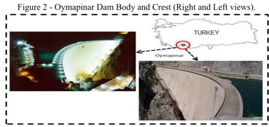
Oymapinar dam is a concrete arch dam that is located on Manavgat brook, which is 18 km north of town of Manavgat, Antalya (Figure 2). Its height is double curved 185 m and its length is 360 m crest long. Construction of the dam began at 1977 and it was put into service at 1983. Dam contains 4 turbines that have 135 mwat power each and an underground hydroelectric central with 540 mwat total power. Length of the reservoir is 5 km, maximum water capacity is 185 m and the volume is 310.106 m3.
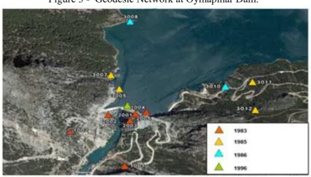
A study conducted at 1985-86 by Geomatic Engineering department of our university on geodesic study of deformations detection on this dam, was examined in order to obtain information on structure of the dam and its surroundings, before starting to take TLS measurements (ERKAYA et al., 2009). Preliminary information on changes of water levels on dam body was obtained by investigating measurement campaigns that spans 17 measuring periods. Current geodesic network points were checked to see if they can be used as scanning points. A geodesic control network, which was implemented in order to detect the changes on the dam body, was formed by 25 objects on five different altitude levels (182 m, 150 m, 125 m, 100 m and 75 m) that represent 6 reference points (1001, 1002, 2001, 2002, 2003, 2005) that represents the dam body at 1983 when the dam was put into service. 4 new reference points (3005, 3007, 3011, 3012) were added to the well side at 1985 and 2 new reference points (3008, 3010) were added at 1986 in order to detect erosion on slopes on the well side (Figure 3). At 1996, geodesic control network became a 13 point network with the addition of a new point on crest wall for reinforcing the river mouth-well connection (Erkaya et al., 2009). All the reference points are displayed at Figure 3.
Figure 3 - Geodesic Network at Oymapinar Dam.
3.2 Equipment’s
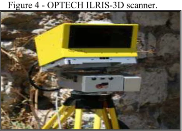
In this application the ILRIS-3D terrestrial laser scanner manufactured by OPTECH Company, was used (Figure 4). This laser scanner has properties such as, 2000 point shot per second, scanning range up to 1500 m, 0.0015 degree angle precision, operability with computer or hand-held computer, remote connection with Ethernet or wireless connection, 7mm precision at 100 m, 3600 x 3600 scanning area, no damage to human health due to use of first class laser, internal 6.6 mega pixel digital camera support and light compact design. The 2002 named point is compatible with maximum/minimum distance limits of the OPTECH ILRIS-3D (Figure 3). In this study, the editing, filtering, registration and georeferencing of point clouds for each scanning was applied by PolyWorks V10.1 and Surface Matching were performed by Surfer 9.0.
Figure 4 - OPTECH ILRIS-3D scanner.
3.3 Data Description
Figure 5 - Natural Targets on Body Dam.
The OPTECH ILRIS-3D scanner was setup with a pan-tilt on reference point 2002 on Oymapinar dam. Pan-tilt is a device that enables scanner to take measurement on different angles on vertical and horizontal directions. Scanners batteries were used as the power source. The view of the dam body on the scanner control software within the field of view is displayed on Figure 6. The dam surface is divided into different frames in order to provide the most appropriate resolution based on the distance to point cloud that represents the dam surface (Figure 6). For each frame, the distance between the scanner and the dam surface was calculated with the software and the appropriate resolution was determined. This is because the distances from point 2002 to dam body varies between 40 m to 300 m. Scanning the dam body using only one frame results in denser point sets in close distance and sparser point sets in longer distance. Due to properties of the scanner we used, the distance between two points in the point cloud is determined based on the variation of angles.
Based on scanning time, size of the dam and smoothness of the surface, general scanning resolution was set to 5 cm for accurately obtaining the surface of the dam body. Also, for verification of the surface model, scannings with fewer points and lower resolutions was performed by setting the scanning resolution o 10 cm, 15 cm, 20 cm, 25 cm and 30 cm. These additional scannings were performed at every scanning period. Redundant points were filtered based on distance and reflection values provided by the software.
3.4. Data Analysis
Integration of different scanning surfaces and transformation to geodesic network coordinate system was performed with indirect integration and positioning method. Since scannings were performed from a single point, all the points that represent the dam body surface were in scanners coordinate system initially. Sequential and overlapping scanning areas that form the whole dam body surface were displayed on Figure 6. Integration of these overlapping areas was performed by the ICP (iterative closes point) module in PolyWorks V10.1 software based on the distance between the points. The dam surface data that was integrated in scanners coordinate system were transformed to geodesic network coordinate system in mm precision for every period with the help of LEICA TPS 1201 Total Station (2 mm + 2 ppm (distance accuracy), 0.3 mgon (angle accuracy)) measurements performed on point 2002 and the distinct targets on dam surface.
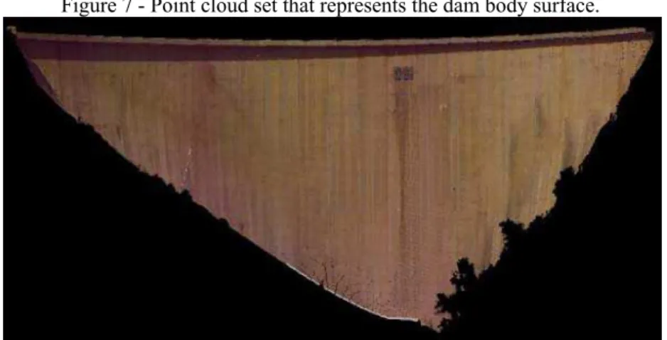
The point cloud that represents the whole dam body surface was obtained after the integration and positioning process (Figure 7).
Figure 7 - Point cloud set that represents the dam body surface.
processing is a surface consisting of meshes. Meshing is formed by connecting all the points in the point cloud with little triangles. Generating a high quality mesh needs cleaning the data (noise reduction, removal of rough points), sampling (number of points), meshing, filling of empty spots on the surface and mesh optimization. After regularizing the point cloud obtained from scanning process, the critical part is generating a 3D model from the regularized point set. If the scanned object has a simple geometric structure, then 3D model can be obtained by drawing simple drawings with a CAD software. If the object has a complex geometric structure, then surface network model needs to be formed. This surface network is obtained with meshing by using software. Since meshing is performed automatically by the software, no meshes and/or redundant meshing may be formed in some places, and there may be errors in meshing in some places. Regularization of these meshes and filling of empty spots can be performed by the software user by using the software modules.
Solid model of the scanned object or area may be formed from the surface model. For visualization of the object, texture, image and etc. can be embedded into surface network. With these processes, realistic 3D models of the scanned objects can be obtained. Additionally, coordinates, distances and angles, RGB values of the point clouds can also be obtained from the software after the scanning. Obtained models can exported in DXF format for using in CAD software, in ASCII format for surface modeling and VRML format for visualization. Realistic data can be obtained from the final product model. 3D surface model obtained from all these processes is displayed in Figure 8. Position of the points, objects size, surface, area and volume can be obtained from the generated model. The generated model can be exported to other software by saving it in different file formats.
As it was discussed in Schäfer et al. (2004), structural monitoring by TLS is done by comparing surfaces to methods based on scanned objects surface (area). Deformations and translations can be detected by comparing the data obtained from different epochs, where mathematical surfaces related to measured points were taken into consideration. When the different point clouds in different reference systems are positioned, comparison between the interpolated surfaces allows computation of translations on the object surface. Detection of transformations on the scanned object or area is done with in different steps by surface differences. In the first step, points are transformed to surfaces by Delaunay triangulation algorithm. With the help of these triangles, an equivalent grid (for x and z coordinates) for each point cloud can be computed (Figure 9). Later, for each sampled point a new value interval (y) can be found. In other words, the difference in y direction for two surfaces that overlap in x and z directions yields the amount of deformation.
Figure 9 - Transformation from point cloud to surface and detection of deformations between two different time intervals (Schäfer et al. 2004).
4. RESULTS AND DISCUSSION
scanned surface, the accuracy of the laser scanner being used, accuracy of georeferencing and registration in data assessment, data editing, filtering, steps in 3-D modeling etc. All these factors deteriorate the accuracy of point positioning. In practice, analysis of point cloud data by laser scanning is difficult. In this study, a procedure was followed by checking the repeatability of laser data which were calculated by comparing the data obtained in similar conditions. The accuracy of the laser scanner being used is 7mm for per 100m and the accuracy of surface model from the results of the repeatability analysis is about few cm levels. The results were presented in detail in the figures 11, 12, 13, 14, 15, 16.
Aim of this study is testing the replicability of data obtained with OPTECH ILRIS-3D, generating a realistic 3D model of the dam body surface and checking if there is a significant difference between the surfaces by using surface different methods. For this reason, 4 measurements were performed on 4 different time intervals where the water level in the reservoir was the same (175 m). Aim of the future work is to examine the effect of changes in the water levels on the dam by using terrestrial laser scanners.
Based on the models generated from equivalent conditions and water levels, determination of translations on the dam was done by comparing the differences in y direction. Initially, only the difference between first and second surfaces was considered. Obtained differences (difference between surface 1 and 2) were classified within itself. Figure 10 shows which intervals maximum and minimum differences belong and the percentage of this difference on total difference on that interval.
Figure 10 - Surface Differences in Dam Body (1st and 2nd Surface) and Distribution of Differences (cm)..
Surface Differences Distribution %
99
98
96
94
Distributions of points were examined to determine which intervals the big differences belong. Examination of colored scale surface differences above clearly shows that 94% of the data is between -0,1 mm and 0,1 mm. Distribution of the remaining points is presented on Table 2.
Table 2 - Distribution of points based on maximum and minimum surface differences (%).
Maximum (mm) Minimum (mm) Point Distribution (%)
Next, computability of 4 different surface models obtained from 4 different scannings was examined. Surfaces of these models were matched and differences were compared statistically. Point distributions and matching of object surfaces are critical processes for analysis of the data obtained from different scannings, where the water level as high, low and medium.
Figure 11: 1st Surface- 2nd Surface (Y direction) Differences (cm)
Figure 12: 1st Surface- 3rd Surface (Y direction) Differences (cm)
Figure 14: 2nd Surface- 3rd Surface (Y direction) Differences (cm).
Figure 15 - 2nd Surface- 4th Surface (Y direction) Differences (cm).
Figure 16 - 3rd Surface- 4th Surface (Y direction) Differences (cm).
laser signal on the corners was the source of differences and errors. Statistical results obtained from surface differences also provide similar results (Table 3).
Table 3 - Statistical Results (meter) Obtained from Surface Differences (within
±
10 cm)1st SURFACE
–
2nd SURFACE
1st SURFACE
–
3rd SURFACE
1st SURFACE
–
4th SURFACE
Number of Points 2474611 2470044 2472713
Mean 0.00085 -0.00018 -0.000416
Median 0.00021 -0.000103 -0.000148
Variance 0.000308 0.000294 0.000332
Standard Deviation 0.01757 0.017144 0.018207
2nd SURFACE
–
3rd SURFACE
2nd SURFACE
–
4th SURFACE
3rd SURFACE
–
4th SURFACE
Number of Points 2470058 2469699 2468555
Mean -0.000583 -0.001004 -0.000215
Median -0.000214 -0.000256 -0.0000347
Variance 0.000302 0.000345 0.000323
Standard Deviation 0.017375 0.018587 0.017968
5. CONCLUSIONS AND SUGGESTIONS
In this work, deformation measurements obtained with TLS under the same water levels on Oymapinar dam was examined. There dimensional models of the Dam body were obtained from four different scans. For repeatability, six surface model differences (1-2, 1-3, 1-4, 2-3, 2-4, 3-4) were produced from the comparison of 3D surface models. Standard deviations from these comparisons vary between 0.0171 and 0.0186. Similar results were also obtained from the comparisons of colored surface difference scales drawn by ±10 cm intervals. The differences showed that they were normally distributed and their range in general (94% of them) were between -0,1mm and 0.1mm. Statistics obtained by the comparison of surface difference indicated that they contain similar results and compatible with them. There is no difference between the surfaces acquired from four different scans done at the same conditions and at the same water level. The surface differences produced by repetition of the application of TLS possess almost the same precisions and accuracies. The accuracies of surfaces acquired from the scans at different times at different water levels (min, max, etc.) are important in the assessment of effects and its deformations of water level changes on dam body.
ACKNOWLEDGMENTS
We would like to thank YTÜ Scientific Research Project Coordinator (BAP) for financial support and BİMTAŞ AŞ. Head Office for providing us the laser scanner.
REFERENCES
ALBA, M.; FREGONESE, L.; PRANDİ, F.; SCAİONİ, M.; VALGOİ, P. Structural monitoring of a large dam by terrestrial laser scanning. International Archives of Photogrammetry, Remote Sensing and Spatial Information Sciences 36 (Part 5) (on CD-ROM), 2006.
BİTELLİ, G.; DUBBİNİ, M.; ZANUTTA, A. Terrestrial laser scanning and digital photogrammetry techniques to monitor landslides bodies. International Archives of Photogrammetry, Remote Sensing and Spatial Information Sciences 35 (Part B5), p. 246–251, 2004.
BOEHLER, W.; BORDAS VİCENT, M.; MARBS, A. Investigating laser scanner accuracy. Proc. CIPA XIXth Int. Symposium, Antalya, Turkey, 30 September– 4 October, p. 696–702, 2003.
ERKAYA, H. et al. Beton Kemer Barajlarda Deformasyonların Modern Ölçme Teknikleri ile Belirlenmesi. TMMOB Harita ve Kadastro Mühendisleri Odası,
12. Türkiye Harita Bilimsel ve Teknik Kurultayı, 11 – 15 Mayıs 2009, Ankara, Turkey
GORDON, S. et al. Structural Deformation Measurement Using Terrestrial Laser Scanners. 11th FIG Symposium on Deformation Measurements, Santorini, Greece, 2003.
GUARNIERI, A. et al. 3D Surveying for Structural Analysis Applications. 12th FIG symposium on Deformation Measurements, Baden, Austria, 2006.
GRUEN, A.; AKCA, D. Least squares 3D surface and curve matching. ISPRS Journal of Photogrammetry and Remote Sensing 59 (3), p. 151–174, 2005 HEİNE, E.; REİNER, H. & TARONGER, J.: 3D risk mapping: preparing learning
material on the use of laser scanning for risk assessment of public infrastructure., International Workshop on the application of terrestrial laser scanning for risk mapping, Valencia, SPAIN, DEZ 12, 1(978-84-8363-199-7), p. 77-88, 2007.
HESSE, C.; STRAMM, H. Deformation measurements with laser scanners - possibilities and challenges. Proc. International Symposium on Modern Technologies, Education and Professional Practice in Geodesy and related Fields, Sofia, 4–5November, p. 228–240, 2004.
SCHNEİDER, D. Terrestrial laser scanner for area based deformation analysis of towers and water damns. Proc. 3rd IAG Symposium of Geodesy for Geotechnical and Structural Engineering and 12th FIG Symposium on Deformation Measurements, Baden, Austria, 22–24 May, p. 6, On CDROM, 2006.
RUDİG, S. Analyse flächenhafter Deformationen aus Laserscannerdaten. VII, 108 Bl. Dissertation, Innsbruck University (PhD Thesis, in German), 2005.
LEMMENS, M. Product survey 3D laser mapping. GIM International 18 (12), p. 44–47, 2004.
PFEİFER, N.; LİCHTİ, D. Terrestrial laser scanning. GIM International 18 (12), p. 50–53, 2004.
SCHÄFER T.; WEBER T.; KYRİNOVİČ P.; ZÁMEČNİKOVÁ M. Deformation Measurement using Terrestrial Laser Scanning at the Hydropower Station of Gabcikovo. INGEO 2004 and FIG Regional Central and Eastern European Conference on Engineering Surveying Bratislava, Slovakia, November 11-13, 2004.
SCHROEDEL, J. et al. Engineering and Design-Structural Deformation Surveying.
US Army Corps of Engineers, Department of the Army, EM 1110-2-1009, 1 June 2002, 20314-1000, Washington, DC.
STAİGER, R. Terrestrial Laser Scanning – Technology, Systems and Applications. In: Proceedings of 2nd FIG Regional Conference, Marrakech, Morocco, and December 2 – 5, 2003.
RESHETYUK Y. Self-calibration and direct georeferencing in terrestrial laser scanning. Doctoral thesis in Infrastructure, Geodesy Royal Institute of Technology (KTH), Department of Transport and Economics, Division of Geodesy, 100 44, Stockholm, January, 2009.


