Cross-lin kin g Electrospun Polydioxan on e-Soluble Elastin
Blen ds: Material Characterization
Michael J. McClure, Scott A. Sell, Catherine P. Barnes, Whitney C. Bowen, Gary L. Bowlin, Ph.D.
Virginia Commonwealth University, Richmond, Virginia, USA
Correspondence to:
Gary L. Bowlin, Ph.D. email: [email protected]
ABSTRACT
The purpose of this study was to establish whether material properties of elastin co-electrospun with polydioxanone (PDO) would change over time in both the uncross-linked state and the cross-linked state. First, uncross-linked scaffolds were placed in phosphate buffered saline (PBS) for three separate time periods: 15 minutes, 1 hour, and 24 hours, and subsequently tested using uniaxial materials testing. Several cross-linking reagents were then investigated to verify their ability to crosslink elastin:
1-ethyl-3-(dimethylaminopropyl)-carbodiimide (EDC), ethylene glycol diglycidyl ether (EGDE), and genipin. Uniaxial tensile testing was performed on scaffolds cross-linked with EDC and genipin, yielding results that warranted further investigation for PDO-elastin blends. Material properties of the cross-linked scaffolds were then found within range of both pig femoral artery and human femoral artery. These results demonstrate PDO-elastin blends could potentially be favorable as vascular grafts, thus warranting future in vitro and in vivo studies.
INTRODUCTION
For over a hundred years, cardiovascular disease (CVD) has remained the number one cause of death in the United States. In 2003, preliminary mortality data showed CVD accounted for 37.3% of all deaths (16.7% of those people were under the age of 65). Atherosclerosis accounted for three quarters of deaths related to CVD. This thickening of arterial wall due to disrupted blood flow can lead to a myriad of complications [1, 2]. In an attempt to treat patients with this disease, an estimated 467,000 bypass surgeries occurred in 2003 [1].
Currently, for small diameter (< 6mm) vascular grafts, autologous blood vessels, such as the saphenous vein, are the standard. However, many patients do not have a suitable vessel for use because of peripheral vascular disease, amputation, or prior harvest [3-5]. If autologous blood vessels are unavailable, then the replacement must be prosthetic.
Several options are available when choosing among the number of grafts currently on the market. The most common options are expanded Polytetrafluoroethylene (ePTFE) and Dacron®. However, at the small diameter level, the properties of these materials have generally proved inadequate due to acute thrombogenicity of the graft, anastomotic intimal hyperplasia, aneurysm formation, infection, and progression of atherosclerotic disease [4]. Therefore, new design criteria must be implemented. Qualities of an ideal design would include the ability to be nonthrombogenic, nonimmunogenic, infection resistant, capable of inducing an appropriate healing response, flexibile, kink resistant, easily manufactured, affordable, easily stored, available in a variety of sizes (lengths and diameters), and mechanically compliant [2, 4, 6, 7].
Arteries require a complex design in order to withstand high flow rates and high pressures at pulsatile intervals. The vessels themselves can be considered as viscoelastic tubes, where their diameter is maintained by the balance between elasticity and strength imparted by the different components of the wall and the applied transmural pressure [8-10]. These tubes experience two primary hemodynamic forces: the circumferential force resulting from the wall tension due to blood pressure, and the frictional force or shear stress resulting from blood flow along the vessel wall. The relationship between shear stress, vascular restructuring, and growth has led to speculation of an association between shear stress and the formation of atherosclerotic lesions [11]. Therefore, in low flow environments, such as small diameter blood vessels, it is essential to match the mechanical forces of a vascular graft with the native artery for proper graft functionality.
To elicit these specific properties, the proper choice of polymers and fabrication must be made. While other scaffold fabrication techniques exist for vascular conduits, electrospinning has emerged as
Journal of Engineered Fibers and Fabrics http:/ / w w w .jeffjournal.org
Volum e 3, Issue 1 - 20 0 8
one of the leading techniques for generating biomimetic scaffolds made of synthetic and natural polymers. Electrospinning uses an electric field to control the formation and deposition of polymer fibers and is remarkably efficient, rapid, and inexpensive [12]. Using this technique, a number of biomaterial constructs have been fabricated [13], including constructs that hold potential for blood vessel engineering [14]. Previous research has shown collagen types I and III, elastin, and PDO to be readily spinnable into submicron scale fibrous scaffolds [2, 15-19]. Therefore, creating a scaffold that combines the mechanical strength of a biodegradable polymer with the bioactive properties of the ECM could prove to be a beneficial design in the quest for a bioresorbable vascular grafts [20]. Ideally, once these scaffolds are processed and implanted in situ, cells will recognize the surface, adhere, migrate, and proliferate.
In vivo elastin [21-23] strongly differs from its soluble form [24], α-elastin and β-elastin, which is commonly used in vascular engineering scaffold fabrication. Previous experiments have blended collagen and elastin scaffolds [2, 15], leading to the instantaneous dissolution of the electrospun fibers in water as demonstrated by Buttafoco et al. However, the characteristics of elastin dissipation, when co-electrospun with PDO, are unknown. Therefore, cross-linking the scaffolds may be a necessity. The most common crosslinker, glutaraldehyde, has been used with numerous types of electrospun scaffolds [2, 16, 25-28], but with cytotoxic drawbacks [29]. Carbodiimide and genipin, on the other hand, have exhibited lower cytotoxicity [29-31], making them better suited for implantation.
This study focused on the 50:50, 60:40, 70:30, 80:20, 90:10, and 100:0 PDO:α,β−elastin blend ratios, and their behavior as an uncross-linked scaffold when immersed in PBS solution for three separate time periods: 15 minutes, 1 hour, and 24 hours. All scaffolds were tested for dry weight loss and material properties. Cross-linked scaffolds were subsequently investigated to determine if any material property changes occurred over time.
METHODS
Electrospinning
The following were blended in ratios of 100:0, 90:10, 80:20, 70:30, 60:40, 50:50, and 0:100 (250 mg/ml for electrospinning pure elastin fibers) by volume (PDO:Elastin) and dissolved in 1,1,1,3,3,3 hexafluoro-2-propanol (Sigma Aldrich Co.): PDO (Ethicon, Inc.) with a concentration of 100 mg/mL
and elastin concentration from bovine neck ligament,
α-elastin and β-elastin, (Elastin Products Co., Inc.) of 200 mg/mL. These solutions were then inserted into a plastic 5 ml Becton Dickinson syringe with a blunt tip 18 gauge Becton Dickinson PrecisionGlide® needle. The syringe and needle were placed in a KD Scientific syringe pump to be dispensed at a rate specific to the PDO:Elastin blend (between 4 and 8 ml/hr). The solutions were electrospun onto a flat rotating mandrel (2.5 cm wide x 10.2 cm long x 0.3 cm thick) to produce a flat sheet with random fiber orientation for weight testing and uniaxial tensile testing. Each sample was electrospun with an applied voltage of 22 kV at a distance of 10-13 cm from the needle tip to the mandrel and a rotational speed of 500 revolutions per minute (rpm).
Weight Loss After Hydration
Scaffolds were cut randomly into rectangular shapes (approximately 1.5cm x 1cm) from the electrospun sheet, weighed, and randomly placed into a specific time group (15 minutes, 60 minutes, or 24 hours) based on elastin’s instantaneous dissolution in PBS. The scaffold was placed in a 35x10mm Petri dish with 3mL of PBS for the specified time. The scaffolds were then extracted and washed 3 times with 3 mL of deionized water. The scaffolds were placed in a desiccation chamber for 24 hours to dry. Each sample was then weighed to determine any weight loss (percent remaining)
% Remaining 100
WeightInitial WeightTime×
= (1)
where WeightTime was specified as the weight remaining after being soaked in PBS and dried, and WeightInitial was specified as the initial dry weight of the sample prior to its PBS soak.
Dry Scaffold Characterization
Uniaxial Tensile Testing
Uniaxial tensile testing was performed on dry and hydrated samples at each time point. Uniaxial tensile testing was also performed on ePTFE, 100% electrospun elastin, and decellularized pig femoral artery. “Dog-bone” shaped samples were punched from the electrospun mat (2.75 mm wide at their narrowest point with a gage length of 7.5 mm) and tested on a MTS Bionix 200 testing system with a 50 N load cell (MTS Systems Corp.) and an extension rate of 10.0 mm/min. Tangential modulus, peak stress, and strain at break were calculated using TestWorks version 4. The sample size for each specimen was n = 6.
Cross-linking
Scaffolds were cross-linked using 1-ethyl-3-(3-dimethylaminopropyl)-carbodiimide (EDC, Fluka Biochemika), genipin (Wako Pure Chemical Industries, Ltd.), and ethylene glycol diglycidyl ether (EGDE, Sigma Aldrich, Inc.).
Cross-linking with EDC
For EDC crosslinking a 50x molarity solution (166.5mM) was prepared in accordance with Barnes et al. [32] in ethyl alcohol (Fisher Scientific). Scaffolds were placed in the EDC solution, and allowed to cross-link for 18 hours followed by a 0.1M Na2HPO4 rinse for 1 hour and a PBS rinse for 1 hour.
Cross-linking with Genipin
A 30mM solution of genipin dissolved in ethyl alcohol was used to cross-link elastin scaffolds. Scaffolds were electrospun and placed in the cross-linking solution for a period of 72 hours [33], followed by a PBS rinse for 2 hours.
Cross-linking with EGDE
Based on the work performed by Leach et al. [34], elastin scaffolds were cross-linked using 50% EGDE. At room temperature electrospun elastin scaffolds were placed in a Petri dish with EGDE and allowed to crosslink for 24 hours followed by a PBS rinse for 2 hours.
Visual Inspection of Cross-linked Scaffolds
Cross-linked scaffolds were initially placed in PBS for a 24 hour period to determine structural stability. Observations were recorded at time intervals of 0 minutes, 15 minutes, 1 hour, and 24 hours and scaffolds were subsequently measured for free amine groups.
Determination of Free Amino Groups
The concentration of free primary amine groups present in cross-linked electrospun elastin was determined using 2,4,6-trinitrobenzenesulfonic acid (TNBS, Research Organics) [32]. Scaffold samples were electrospun, punched into “dog bone” shapes, massed and cross-linked using the procedures listed above. Samples were placed in 15mL Fisherbrand® centrifuge tubes. NaHCO3 (1.0 mL 4% w/v) and TNBS (1.0 mL 0.5% w/v) were added and placed in an incubator at 40oC for 2 hr. 3.0 mL of 6M HCL was then added to the solution, which was placed in an oven at 60oC for 2 hr. The samples were diluted with 9 mL of PBS, cooled to room temperature. The absorbance at 345 nm was measured using a
SPECTRAmax® PLUS384 microplate
spectrophotometer. Measured absorbance values were then placed into a percent cross-linking equation
⎥ ⎥ ⎥
⎦ ⎤
⎢ ⎢ ⎢
⎣ ⎡ − = −
nc Mass nc Abs
c Mass c Abs 1 linked Cross
% (2)
where Absc is the measured absorbance of the cross-linked solution, Absnc is the measured absorbance of the non-cross-linked solution, Massc is the dry mass of the cross-linked scaffold, and Massnc is the dry mass of the non-cross-linked scaffold. The sample size for each measured absorbance group was n = 9.
Statistical Analysis
Anaylsis of variance (ANOVA) was performed in NCSS® 2004 statistical software (NCSS, USA) using a Kruskal-Wallis test (p < 0.01) to determine if at least two medians were different, and a Tukey-Kramer pair wise multiple-comparison test (p<0.01) to ultimately determine significant differences between groups.
RESULTS & DISCUSSION
Weight Loss After Hydration
Soluble elastin is known to immediately dissociate into aqueous solutions. PDO and elastin were electrospun together in order to demonstrate the possibility of PDO retaining the elastin fibers. Thus, PDO could prevent elastin dissociation in PBS without a cross-linking agent.
The total weight of each electrospun scaffold illustrated the relationship between the different blends of PDO and elastin; as the amount of elastin increased, the weight of the dry scaffold increased as
Journal of Engineered Fibers and Fabrics http:/ / w w w .jeffjournal.org
Volum e 3, Issue 1 - 20 0 8
well. Once hydrated, the results indicated that as the amount of elastin was increased, the faster the scaffold degraded or dissociated. PDO:Elastin blends of 50:50 experienced a 50.4% reduction in the weight of the scaffold in the first 15 minutes alone. After 24 hours an additional 10.1% reduction in weight occurred, creating an almost exponential decrease. As the initial amount of elastin in the scaffolds was reduced, weight loss over time tended to become more linear (Figure 1, Table I).
TABLE I.
Average Remaining Dry Weight
Graft Material
Remaining 15 minutes
(%)
Remaining 60 minutes
(%)
Remaining 24 hours
(%)
50:50 50 ± 12 41 ± 7.5 39 ± 5.9
60:40 71 ± 17 64 ± 11 58 ± 2.7
70:30 94 ± 2.5 77 ± 3.9 67 ± 5.2
80:20 96 ± 3.3 91 ± 7.4 85 ± 2.1
90:10 106 ± 5.8 107 ± 7.0 99 ± 3.6
100:0 100 ± 2.9 100 ± 3.8 102 ± 2.0
0 20 40 60 80 100 120
50:50 60:40 70:30 80:20 90:10 100:0
PDO:Elastin
Weight
R
e
m
a
ining (
%
)
0 min 15 min 1 hr 1 day
Figure 1. Percent of scaffold weight remaining after t = 0 minutes,
he initial weight was significantly different from 15
s there was no change in PDO content of the
15 minutes, 60 minutes, and 24 hours, respectively in PBS.
T
minutes, 60 minutes, and 24 hours for both blends of 50:50 and 60:40; however, the 15 minutes, 60 minutes, and 24 hours blends were not different from each other. Therefore, the two blends lost most of their weight in the first 15 to 60 minutes, leading to a slowed rate of loss as time progressed. Significant differences existed among the three timed groups for 70:30, but not between the initial weight and 15 minute batch time. Differences existed between the
initial weight, 60 minutes, and 24 hours batch times for 80:20. However, initial weight and 15 minutes did not exhibit any differences for 80:20. This result indicates the scaffolds were retaining their weight in the first 15 minutes in PBS, but as time progressed there was a significant drop in scaffold weight. 90:10 and 100:0 results demonstrated no significant differences.
A
scaffolds over such a short exposure to an aqueous environment, all weight loss is attributed to the dissolution of elastin. Results indicate as the elastin content decreased, it took longer for the elastin to dissipate out of the scaffold. This can be clearly observed in the 80:20, 70:30, 60:40, and 50:50 scaffolds, where a logarithmic relationship exists between time and weight percent (Figure 2).
R2 = 0.94
R2 = 0.98
R2 = 0.61
R2 = 0.72
0 20 40 60 80 100 120
0 500 1000 1500 2000
Time (min)
W
ei
g
h
t P
er
cen
t
50:50 60:40 70:30 80:20
igure 2. Weight percent of PDO:Elastin blends 50:50, 60:40,
o, as elastin content increased its ability to dissipate
F
70:30, and 80:20 vs. time (0, 15, 60, and 1440 minutes). The data is fit to a logarithmic curve where R2 values display the degree of
association between weight percent and time.
S
Journal of Engineered Fibers and Fabrics http:/ / w w w .jeffjournal.org Volum e 3, Issue 1 - 20 0 8
5 the dissipation of elastin from the scaffold is slowed, or possibly stopped.
Dry Scaffold Characterization
onstrated that Scanning electron microscopy dem
PDO and elastin were successfully electrospun into a
random non-woven mat Figure 3. This is
demonstrated by the thin, flat, ribbon-like fibers which represent elastin compared to the more rounded fibers which represents PDO. Mean fiber diameter and pore area were calculated for all scaffold types, where mean fiber diameter ranged from 0.88 – 0.56 μm and mean pore area ranged from 4.7 – 1.5 μm2.
Figure 3. Scanning electro micrograph of electrospun
PDO ion
ncross-linked PDO:Elastin Uniaxial Tensile n
:Elastin. All micrographs are taken at 2500x magnificat and the scale bar is equivalent to 10 microns.
U Testing
As weight sampling indicates, elastin dissociation
d hydrations of 15 minutes, 60 minutes, and 24 hours.
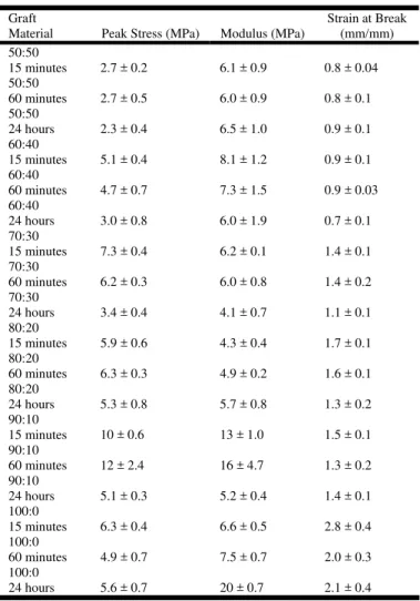
Material Properties Of Un Pdo:Elastin At Times Of 15 Minutes, 24 Hours
Graft
Ma ial Peak Str
reak (mm/mm)
definitely occurs in some blends over time. Consequently, scaffold mechanical properties could also change with time. Results of uniaxial tensile testing are displayed in Figure 4 and Table II with peak stress, tangential modulus, and strain at break. The scaffolds were tested dry as well as at time
Timed hydration results for peak stress indicated there were no differences among the 50:50 scaffolds. Samples at 24 hours were different from both 15 minutes and 60 minutes among the 60:40 scaffolds. Among the 70:30 scaffolds, times of 15 minutes, 60 minutes, and 24 hours were different from each other. There were no significant differences among the 80:20 scaffolds. 90:10 scaffolds showed significant differences between 24 hours and both 15 minutes and 60 minutes. The group timed at 15 minutes was different from those timed at 60 minutes in the pure PDO scaffold. One possible difference that could account for the differences seen in 90:10 and pure PDO scaffolds are batch to batch differences in PDO or elastin that occur during the electrospinning process for use in the 24 hours hydration. Due to the preliminary nature of this study, further investigation is required.
TABLE II.
cross-Linked 1 Hour, And
ter ess (MPa) Modulus (MPa)
Strain at B
50:50 15 minute
s 2.7 ± 0.2 6.1 ± 0.9 0.8 ± 0.04 50:50
60 minutes 2.7 ± 0.5 6.0 ± 0.9 0.8 ± 0.1 50:50
24 hours 2.3 ± 0.4 6.5 ± 1.0 0.9 ± 0.1 60:40
15 minutes 5.1 ± 0.4 8.1 ± 1.2 0.9 ± 0.1 60:40
60 minutes 4.7 ± 0.7 7.3 ± 1.5 0.9 ± 0.03 60:40
24 hours 3.0 ± 0.8 6.0 ± 1.9 0.7 ± 0.1 70:30
15 minutes 7.3 ± 0.4 6.2 ± 0.1 1.4 ± 0.1 70:30
60 minutes 6.2 ± 0.3 6.0 ± 0.8 1.4 ± 0.2 70:30
24 hours 3.4 ± 0.4 4.1 ± 0.7 1.1 ± 0.1 80:20
15 minutes 5.9 ± 0.6 4.3 ± 0.4 1.7 ± 0.1 80:20
60 minutes 6.3 ± 0.3 4.9 ± 0.2 1.6 ± 0.1 80:20
24 hours 5.3 ± 0.8 5.7 ± 0.8 1.3 ± 0.2 90:10
15 minutes 10 ± 0.6 13 ± 1.0 1.5 ± 0.1 90:10
60 minutes 12 ± 2.4 16 ± 4.7 1.3 ± 0.2 90:10
24 hours 5.1 ± 0.3 5.2 ± 0.4 1.4 ± 0.1 100:0
15 minutes 6.3 ± 0.4 6.6 ± 0.5 2.8 ± 0.4 100:0
60 minutes 4.9 ± 0.7 7.5 ± 0.7 2.0 ± 0.3 100:0
24 hours 5.6 ± 0.7 20 ± 0.7 2.1 ± 0.4
50:50 60:40
70:30 80:20
Trends of the tangential modulus results closely sembled those of peak stress for the 50:50, 60:40, re
and 70:30 samples. Among the 80:20 scaffolds, the batch timed at 15 minutes was different from the batch timed at 24 hours. This discrepancy was also true for the 90:10 and 100:0 blends, where times of 15 minutes and 60 minutes were different from 24 hours in the 90:10 and pure PDO scaffolds. 90:10 actually increased in stiffness from 15 minutes to 60 minutes, but dropped dramatically after 24 hours. Results for 80:20 and 90:10 could once again be due to batch differences in elastin or PDO; however, further investigation is required to determine this.
0 2 4 6 8 10 12 14 16
50:50 60:40 70:30 80:20 90:10 100:0
PDO:Elastin Ratio
P
eak S
tress (M
P
a)
Dry 15 min 1 hr 1 day
0 10 20 30 40 50 60 70
50:50 60:40 70:30 80:20 90:10 100:0 PDO:Elastin Ratio
Ta
ng
e
nt
ia
l M
odul
us
(M
P
a
)
Dry 15 min 1 hr 1 day
0 0.5 1 1.5 2 2.5 3 3.5
50:50 60:40 70:30 80:20 90:10 100:0
PDO:Elastin Ratio
S
trai
n
at Break (m
m
/m
m
) Dry 15 min 1 hr 1 day
Figure 4. Comparison of uniaxial tensile test values for peak stress, modulus, and strain at break, for uncross-linked
o significant differences existed among the 50:50,
aterial properties of the uncross-linked
oss-linking Elastin
PDO:Elastin blends.
N
60:40, and 90:10 scaffolds for strain at break. Among the 70:30 scaffolds, the batch time of 15 minutes is different from 24 hours, and 15 minutes and 60 minutes are different from 24 hours among the 80:20 scaffolds, indicating a change has occurred over a 24 hour period. In addition, the batch timed at 15 minutes is different from 60 minutes in pure PDO scaffolds.
M
PDO:Elastin blends demonstrated overall changes in the scaffolds over a time period of 24 hours. No differences were visible in the 50:50 and 60:40 scaffolds, indicating elastin had dissociated too quickly in the 50:50 and 60:40 scaffolds for any noticeable change to be seen. However, 70:30 scaffolds, demonstrated an overall change from 15 minutes to 24 hours for all material properties, whereby the material became less stiff, peak stress decreased, and strain at break decreased. 80:20 and 90:10 scaffolds showed changes over time as well, but not for all properties. Therefore, the material properties change over a period of one day when the scaffolds are uncross-linked, providing evidence suggesting PDO does not adequately retain the soluble elastin in the scaffolds, making cross-linking a necessity.
Cr
lts for electrospun elastin The cross-linked resu
scaffolds are illustrated in Figure 5, where 166.5 mM EDC had a percent cross-link average of 45.1%, while genipin had an average of 23.3%. EGDE was not calculated because the scaffolds dissociated immediately in NaHCO3 solution prior to incubation, indicating minimal to no cross-linking. Statistical differences existed between the 166.5 mM EDC and 30mM genipin, demonstrating 166.5 mM EDC had the maximum cross-linking among the groups.
0 10 20 30 40 50 60
166.5 mM EDC 30mM Genipin
Cross-linking Reagent
%
X-link
e
d
Figure 5. Percent cross-linkage of EDC and genipin fo electrospun elastin scaffolds.
Journal of Engineered Fibers and Fabrics http:/ / w w w .jeffjournal.org Volum e 3, Issue 1 - 20 0 8
7
Cross-linking PDO:Elastin
of a weig
Figure 6 shows the results ht loss study,
clearly demonstrating elastin retention after cross-linking in a 50:50 PDO:Elastin scaffold after soaking in PBS for 24 hours. There is no statistical difference between the scaffold cross-linked with EDC and the initial weight. However, there is a statistical difference between the initial weight of the uncross-linked scaffold and its final weight after one day.
0 20 40 60 80 100 120
Init ial Weight 50-50 EDC 50-50 NO EDC
% W
e
ig
h
t
R
e
ma
in
in
g
Figure 6. Percent of weight remaining of EDC cross-linked 50:50 PDO:Elastin scaffolds and uncross-linked 50:50 PDO:Elastin
s-linked PDO:Elastin Uniaxial Tensile scaffolds after being soaked in PBS for 24 hours.
Cros Testing
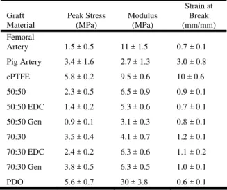
Since EDC had the highest degree of cross-linking, materials cross-linked by this method were the focus of uniaxial tensile testing. The results obtained were compared to ePTFE and pig artery. Peak stress, tangential modulus, and strain at break for particular EDC scaffolds are contained in Table III.
TABLE III
Material Properties Of Ed ed And Uncross-Linked Electrospun Scaffolds Compared To Human Femoral Artery [35,
Graft
Material (MPa) (MPa)
Break c Cross-Link
36], Eptfe, And Decellularized Pig Artery.
Peak Stress Modulus
Strain at
(mm/mm) Femoral
Artery 1.5 ± 0.5 11 ± 1.5 0.7 ± 0.1
Pig Artery
DC
DC
3.4 ± 1.6 2.7 ± 1.3 3.0 ± 0.8
ePTFE 5.8 ± 0.2 9.5 ± 0.6 10 ± 0.6
50:50 2.3 ± 0.5 6.5 ± 0.9 0.9 ± 0.1
50:50 E 1.4 ± 0.2 5.3 ± 0.6 0.7 ± 0.1
50:50 Gen 0.9 ± 0.1 3.1 ± 0.3 0.8 ± 0.1
70:30 3.5 ± 0.4 4.1 ± 0.7 1.2 ± 0.1
70:30 E 2.4 ± 0.2 6.3 ± 0.6 1.1 ± 0.2
70:30 Gen 3.8 ± 0.5 6.3 ± 0.5 1.0 ± 0.1
PDO 5.6 ± 0.7 30 ± 3.8 0.6 ± 0.1
I ure 7, t a no grad ase
stress demonstrated EDC cross-linked
linked pure elastin
of a fairly smooth
n Fig here was ticeable ual incre
in average peak stress of EDC cross-linked PDO:Elastin ranges from 0:100-100:0. Similar to the uncross-linked scaffolds, higher PDO content correlates to a higher peak stress value. Modulus results demonstrated similar values over the PDO:Elastin ranges, 50:50-80:20. However, as PDO content increased after this range, the modulus dramatically increased, which is also consistent with the uncross-linked data. Strain at break results demonstrated increases as the PDO content increased up to the 70:30 blend. However, at this strain at break point it began to fall as it reached 100:0. Therefore, an unknown factor in the cross-linking process may affect the amount the graft is allowed to strain as PDO content increases, or there could have been some batch differences as the scaffolds were electrospun.
verall, peak O
pure elastin was statistically different from all tested materials. 50:50 PDO:Elastin was statistically different from the 80:20-100:0 PDO:Elastin blends, pig artery, and ePTFE. 60:40 was statistically different from PDO:Elastin ranges of 70:30-100:0, ePTFE, and pig artery. 70:30 was statistically different from all materials except 50:50. 80:20-100:0 and ePTFE were statistically different from all materials, and pig artery was statistically different from all materials except 80:20.
n terms of modulus, EDC cross-I
was significantly different from all materials except pig artery. 50:50 and 80:20 were significantly different from ePTFE, 90:10, and 100:0. 60:40 and 70:30 were both significantly different from 90:10 and 100:0 PDO:Elastin blends, as well as the pure elastin. However, 60:40 was also significantly different from the pig artery. 90:10 is significantly different from all materials except ePTFE, and 100:0 was significantly different from all materials. ePTFE was significantly different from 50:50, 80:20, 90:10, pure elastin, and pig artery.
train at break consisted S
the properties provided to the scaffold result in lower strain at break values.
Pig artery was used as a comparison tool for a native
g artery demonstrated an average tangential
he importance of peak stress, tangential modulus,
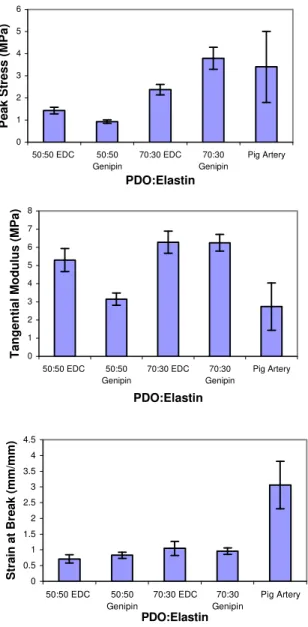
ince genipin’s cytotoxic properties are considered to
statistical differences between the 50:50 scaffolds, extracellular matrix (ECM) containing collagen, elastin, and proteoglycans. The peak stress and tangential modulus of PDO:Elastin blends were all within the range of the pig artery; however, strain at break was not. In native artery, elastin generally takes the majority of the initial load, while collagen stretches from its crimped position. Once the collagen is fully stretched, stress increases dramatically, even though the artery has already stretched a significant amount prior to fracture. While this behavior was observed in the pig artery, the PDO:Elastin scaffolds, on the other hand, do not contain this crimped structure. Thus, PDO and elastin worked together as the scaffold was stretched and subsequently fractured at a lower strain.
Pi
modulus of 2.7 MPa, which is significantly less than all tested materials with the exception of the EDC pure elastin scaffolds. This result illustrated a need for a decrease in the amount of synthetic polymer blended into scaffolds, but at the cost of possible graft failure due to rupture or aneurysmal formation. Therefore, a significant amount of materials testing outside of uniaxial tensile testing is required, including compliance and burst strength, which involve biaxial stretch.
T
and strain at break for vascular graft material properties are to give a preliminary understanding of material behavior if implanted in situ. Peak stress is a good indicator for burst strength properties and prevention of aneurysmal formation. Values obtained through tangential modulus are related to the overall stiffness of the material and are indicative of the material compliance. Strain at break is another indicator for compliance and distensibililty. Individually, these properties only provide small details of the overall picture, but, when combined with a description of the stress-strain curves and more advanced testing, these material properties become more valuable at predicting the mechanical properties of a combination of materials.
S
be conducive to the body, PDO:Elastin blends of 50:50 and 70:30 cross-linked with genipin were examined through uniaxial tensile testing in a side-by-side comparison with EDC cross-linked scaffolds and pig artery (Figure 8). Results revealed no
0 1 2 3 4 5 6 7 8
P
a)
0:
100 E
D
C
50:
50
60:
40
70:
30
80:
20
90:
10
100:
0
0:
100 Geni
pi
n
ePTFE
Pig
Ar
te
ry
PDO:Elastin
P
eak S
tress (M
0 5 10 15 20 25 30 35 40
0:
100 E
D
C
50:
50
60:
40
70:
30
80:
20
90:
10
100:
0
0:
100 Geni
pi
n
ePTFE
Pig
Ar
te
ry
PDO:Elastin
Tangent
ial M
odulus (
M
Pa)
0 2 4 6 8 10 12
0:
100 E
D
C
50:
50
60:
40
70:
30
80:
20
90:
10
100:
0
0:
100 Geni
pi
n
ePTFE
Pig
Ar
te
ry
PDO:Elastin
S
tr
a
in at
B
reak (
mm/mm)
igure 7. Uniaxial tensile test values for peak stress, modulus, and strain at break for EDC cross-linked PDO:Elastin blends, genipin,
a difference e 70:30 scaffolds.
itionally, the 70:30 scaffold cross-linked with
F
ePTFE, and pig artery.
xisted between the but
Add
Journal of Engineered Fibers and Fabrics http:/ / w w w .jeffjournal.org Volum e 3, Issue 1 - 20 0 8
9 which had different strain at break compared to pig artery. Therefore, cross-linking with genipin demonstrates a decrease in the stiffness of the material compared to EDC when enough elastin is added to the scaffold. The same could be true for peak stress since the average peak stress decreases for the 50:50. However, 70:30 demonstrates an increase in peak stress when cross-linked with genipin. Thus, this inconsistency could be due to the cross-linker used or to batch differences with higher PDO content compared to the scaffold cross-linked with EDC.
0 1 2 3 4 5 6
50:50 EDC 50:50 Genipin
70:30 EDC 70:30 Genipin
Pig Artery
PDO:Elastin
P
eak S
tress (M
P
a)
0 1 2 3 4 5 6 7 8
50:50 EDC 50:50 Genipin
70:30 EDC 70:30 Genipin
Pig Artery
PDO:Elastin
Tangent
ial M
odulus (
M
Pa)
0 0.5 1 1.5 2 2.5 3 3.5 4 4.5
50:50 EDC 50:50 Genipin
70:30 EDC 70:30 Genipin
Pig Artery
PDO:Elastin
S
tr
a
in at
B
reak
(
mm/mm)
Figure 8. Uniaxial tensile test values for peak stress, modulus, and strain at break, for EDC and genipin cross-linked PDO:Elastin
blends of 50:50, 70:30, and pig artery.
C
ven pun
PDO-uble elastin blends demonstrate changes in aterial properties over a period of one day when
ading to the conclusion that
cross-n Mid-Atlacross-ntic Affiliate (0555407U,GLB) r funding and The Center for Biomaterials &
dical Devices Group, a
., Heart disease and stroke a report from the American Heart Statistics Committee and Stroke Statistics tee. Circulation, 2006. 113(6): p. e85-151.
w
n vitro.
ar grafting: clinical applications
s. Eur J Vasc Endovasc
pass
steps towards tissue
357-68. ONCLUSION
results have shown that electros The gi
sol m
uncross-linked, le
linking is a necessity for elastin containing scaffolds. Several cross-linkers were investigated for this study, but only EDC and genipin were considered for additional testing based on percent cross-linking and documented cytotoxic properties. Mechanically, the addition of elastin creates scaffolds that exhibited ranges of properties resembling that of both pig artery and native human artery. Previous data indicated uncross-linked PDO-elastin cell culture with blends of 70:30 and 90:10 demonstrated excellent migration into the uncross-linked scaffolds [37]. Future studies will investigate mechanical properties based on uniaxial hysteretic testing, compliance testing, and the possible inclusion of collagen.
ACKNOWLEDGEMENT
We would like to thank the American Heart Associatio
fo
Advanced Technologies, Me
division of Ethicon Inc. for donating virgin PDO for electrospinning.
REFERENCES
[1] Thom, T., et al
2006 update: Association Subcommit
[2] Boland, E.D., et al., Electrospinning collagen and elastin: preliminary vascular tissue engineering.
Frontiers in Bioscience, 2004. 9: p. 1422-1432. [3] 3Sawyer, P.N., Modern vascular grafts. 1987, Ne
York: McGraw-Hill.
[4] Isenberg, B.C., C. Williams, and R.T. Tranquillo,
Small-diameter artificial arteries engineered i
Circ Res., 2005. 98: p. 25-35. [5] Wright, C.B., Vascul
and techniques. 1983, Boston: J. Wright, PSG Inc.
[6] Teebken, O.E. and A. Haverich, Tissue engineering of small diameter vascular graft
Surg, 2002. 23(6): p. 475-485.
[7] Kannan, R.Y., et al., Current status of prosthetic by grafts: a review. J Biomed Mater Res B Appl Biomater, 2005. 74(1): p. 570-81.
[8] Buttafoco, L., et al., First
rk Toronto London:
ersity Press.
. 216-223.
Biochem Biotechnol, 2005. 125(3): p. 147-58.
olecules, 2000. 33: p. 2989-2997.
L. and A.M. Tamburro, Elastin: molecular
F. Davis, The chemistry of
: p.
ological properties. Biomacromolecules, 2005.
Biomed Mater Res A, 2006. 79(3):
affold in a rat cell
rally occurring crosslinking agent (genipin)
c acid scaffold modified by
1-ethyl-ds with carbodiimide
ater
le elastin mimetic
mpany.
fts.
ORS’ ADDRESSES
. Sell, Whitney C.
rine P. Barnes
th University
[9] Loscalzo, J., M.A. Creager, and V.J. Dzau, Vascular medicine: a textbook of vascular biology and diseases. Second ed. 1996, Boston New Yo
Little, Brown and Company. 1312.
[10] Lanza, R., R. Langer, and J. Vacanti, Principles of tissue engineering. Second ed. 2000, Boston: Academic Press. 427-441.
[11] Halliday, A., et al., An introduction to vascular biology from physiology to pathophysiology. 1998, New York: Cambridge Univ
[12] Reneker, D.H. and I. Chun, Nanometre diameter fibres of polymer, produced by electrospinning.
Nanotechnology, 1996. 7(3): p
[13] Stitzel, J., et al., Controlled fabrication of a biological vascular substitute. Biomaterials, 2006. 27(7): p. 1088-94.
[14] Venugopal, J. and S. Ramakrishna, Applications of polymer nanofibers in biomedicine and biotechnology.
Appl
[15] Buttafoco, L., et al., Electrospinning of collagen and elastin for tissue engineering applications.
Biomaterials, 2006. 27(5): p. 724-34.
[16] Matthews, J.A., et al., Electrospinning of collagen nanofibers. Biomacromolecules, 2002. 3(2): p. 232-8. [17] Li, M., et al., Electrospun protein fibers as matrices for
tissue engineering. Biomaterials, 2005. 26(30): p. 5999-6008.
[18] Huang, L., et al., Generation of synthetic elastin-mimetic small diameter fibers and fiber networks.
Macrom
[19] Boland, E.D., et al., Electrospinning polydioxanone for biomedical applications. Acta Biomater, 2005. 1(1): p. 115-23.
[20] Hench, L.L. and J.M. Polak, Third-generation biomedical materials. Science, 2002. 295(5557): p. 1014-7.
[21] Rodgers, U.R. and A.S. Weiss, Cellular interactions with elastin. Pathol Biol (Paris), 2005. 53(7): p. 390-8. [22] Debelle,
description and function. Int J Biochem Cell Biol, 1999. 31(2): p. 261-72.
[23] Vrhovski, B. and A.S. Weiss, Biochemistry of tropoelastin. Eur J Biochem, 1998. 258(1): p. 1-18. [24] Partridge, S.M. and H.
connective tissues. 3. composition of the soluble proteins derived from elastin. Biochem. J., 1955. 61
21-30.
[25] Zhong, S., et al., Formation of collagen-glycosaminoglycan blended nanofibrous scaffolds and their bi
6(6): p. 2998-3004.
[26] Zhong, S., et al., An aligned nanofibrous collagen scaffold by electrospinning and its effects on in vitro fibroblast culture. J
p. 456-63.
[27] Zhao, P., et al., Biodegradable fibrous scaffolds composed of gelatin coated poly(epsilon-caprolactone)
prepared by coaxial electrospinning. J Biomed Mater Res A, 2007.
[28] McManus, M.C., et al., Electrospun fibrinogen: feasibility as a tissue engineering sc
culture model. J Biomed Mater Res A, 2007. 81(2): p. 299-309.
[29] Tsai, C.C., et al., In vitro evaluation of the genotoxicity of a natu
for biologic tissue fixation. J Biomed Mater Res, 2000.
52(1): p. 58-65.
[30] Park, S.N., et al., Characterization of porous collagen/hyaluroni
3-(3-dimethylaminopropyl)carbodiimide cross-linking.
Biomaterials, 2002. 23(4): p. 1205-12.
[31] Huang, L.L., et al., Biocompatibility study of a biological tissue fixed with a naturally occurring crosslinking reagent. J Biomed Mater Res, 1998. 42(4): p. 568-76.
[32] Barnes, C.P., et al., Cross-linking electrospun type II collagen tissue engineering scaffol
in ethanol. Tissue Eng, 2007. 13(7): p. 1593-605. [33] Sung, H.W., et al., Crosslinking of biological tissues
using genipin and/or carbodiimide. J Biomed M Res A, 2003. 64(3): p. 427-38.
[34] Leach, J.B., et al., Crosslinked alpha-elastin biomaterials: towards a processab
scaffold. Acta Biomater, 2005. 1(2): p. 155-64. [35] Fung, Y.C., Biodynamics: circulation. blood flow in
arteries. 1984, New York: Springer-Verlag.
[36] Hiroshi, Y., Strength of biological materials. 1970, New York: Robert E. Krieger Publishing Co
[37] Sell, S.A., et al., Electrospun polydioxanone-elastin blends: potential for bioresorbable vascular gra
Biomedical Materials, 2006. 1: p. 72-80.
AUTH
Michael J. McClure, Scott A Bowen, Gary L. Bowlin, Ph.D.
Virginia Commonwealth University P.O. Box 980694
Richmond, VA 23 USA
298-0694
Cathe
Virginia Commonweal Biomedical Engineering