Nonlinear Analysis of Reinforced Concrete Column with Fiber
Reinforced Polymer Bars
T. Subramani
1, Reni Kuruvilla
2, J. Jayalakshmi
31
Professor & Dean, Department of Civil Engineering, VMKV Engineering College, Vinayaka Missions University, Salem, India.
2, 3
PG Students of Structural Engineering, Department of Civil Engineering, VMKV Engineering College, Vinayaka Missions University, Salem,
ABSTRACT
In this paper, the results of an analytical investigation on the behaviour of RC columns reinforced with fibber reinforced polymer bars FRP are presented and discussed. Nonlinear finite element analysis on 10-column specimens was achieved by using ANSYS software. The nonlinear finite element analysis program ANSYS is utilized owing to its capabilities to predict either the response of reinforced concrete columns in the post-elastic range or the ultimate strength of a reinforced concrete columns reinforced by FRP bars. An extensive set of parameters is investigated including different main reinforcement ratios, main reinforcement types (GFRP, Steel), the transverse reinforcement ratios, and the characteristic compressive strength of concrete. A comparison between the experimental results and those predicted by the existing models are presented. Results and conclusions may be useful for designers, have been raised, and represented.
KEYWORDS:
Nonlinear Analysis, Reinforced Concrete, Column With Fiber Reinforced Polymer Bars,I.
INTRODUCTION
Traditional steel based reinforcement systems for concrete elements are facing with serious problems mainly caused by corrosion due to chemically aggressive environments and salts used in deciding procedures especially in case of bridge steel reinforced concrete girders. Also in some cases special applications require structural members with magnetic transparency. An alternative to this major problem has recently become the use of fiber reinforced polymer (FPR) composite bars as internal reinforcement.
Reinforced concrete structures often have to face modification and improvement of their performance during their service life. The main contributing factors are change in their use, new design standards, deterioration due to corrosion in the steel caused by exposure to an aggressive environment and accident events such as earthquakes. In such circumstances there are two possible solutions: replacement or retrofitting.
Full structure replacement might have determinate disadvantages such as high costs for material and labor, a stronger environmental impact and inconvenience due to interruption of the function of the structure e.g. traffic problems. When possible, it is often better to repair or upgrade the structure by retrofitting.
In the last decade, the development of strong epoxy glue has led to a technique which has great potential in the field of upgrading structures. Basically the technique involves gluing steel plates or
fiber reinforced polymer (FRP) plates to the surface of the concrete. The plates then act compositely with the concrete and help to carry the loads.
1.1 FIBER REINFORCED POLYMER
FRP composite materials have developed into economically and structurally viable construction materials for load bearing elements in buildings and bridges over the last two decades. FRP reinforcements for structural elements in construction have raised the interest of structural engineers since the beginning of the fiber reinforced plastics industry and the use of FRP composite materials with various fiber reinforcement types has become an interesting alternative as reinforcement for various concrete members.
There is nowadays a wide range of available types of FRP composites (with polyester, epoxy or vinyl-ester matrices) reinforced with glass, carbon and aramid fibers with suitable properties for different applications in civil and structural engineering. However, the particularities of behaviour of FRP bars and the insufficient experimental data on structural and long time behaviour of concrete elements reinforced with internal FRP composite bars still requires extensive theoretical studies and experimental programs to be able to fully exploit the potential of these new materials.
Over the latest decades structural strengthening of concrete structures has become an important issue due to ageing of infrastructure and the need for
upgrading to fulfil more stringent design requirements. Also the seismic retrofit has become more important mainly in seismic active areas. The use of fiber reinforced polymer (FRP) composites in strengthening solutions has become an efficient alternative to some of the existing traditional methods due to some advantages such their features in terms of strength, lightness, corrosion resistance and ease of application.
Such techniques are also most attractive for their fast execution and low labour costs. FRP composite products for structural strengthening are available in the form of prefabricated strips, procured shapes or uncured sheets applied through wet lay-up procedure. Prefabricated plates are typically 0.5-1.5 mm thick and 50-200 mm wide, and they are made of unidirectional fibers (glass, carbon, aramid) in a thermosetting matrix (epoxy, polyester, vinyl ester). Uncured sheets typically have a nominal thickness of less than 1 mm, are made of fibers (unidirectional or bidirectional) pre-impregnated or in situ impregnated with resins.
Bonding is achieved with epoxy adhesives when prefabricated composite elements are utilized and with impregnating resins in the latter case. Composites were first applied as confining reinforcement of reinforced concrete (RC) columns, and as flexural strengthening materials for RC bridge girders. Since the first applications the developments have been tremendous and the range of applications has expanded to timber, masonry and metallic materials.
The number of applications involving FRP composites as strengthening materials for RC elements and structures has expanded from a few, about 15 years ago to more than ten thousand nowadays.
FRP can be convenient compared to steel for a number of reasons. These materials have higher ultimate strength and lower density than steel. The installation is easier and temporary support until the adhesive gains its strength is not required due to the low weight. They can be formed on site into complicated shapes and can also be easily cut to length on site. This work is a study of the behaviour of concrete beams retrofitted with carbon FRP (CFRP), using experiments and finite element modelling.
Fiber reinforced polymer (FRP) is increasingly used for reinforcing new structures, and strengthening existing structures. FRP composites, in the form of sheets, cables, rods, and plates, have proven to be a cost-effective alternative to steel reinforcements because of their low weight to strength ratio, corrosion resistance, and flexibility.
The most common types of FRP are aramid, glass, and carbon; AFRP, GFRP, and CFRP respectively. Unfortunately, there was a lack of data
about using FRP as reinforcement; the lack of a comprehensive database on FRP materials makes it difficult for the practicing civil engineer and designer to use FRP composites on a routine basis, although a number of reviews have been published recently related to durability and test methods.
The focus of each has been to summarize the state of knowledge in general without emphasizing or attempting to prioritize critical areas in which needs are the greatest for collection, assimilation, and dissemination of data (Karbhari1, 2003).
Bridge structures all over the world as applications of structures with FRP reinforcement for example:
In China; there are now eight GFRP bridges in China. These bridges were generally constructed by hand lay-up of glass fibers in a polyester resin using a honeycomb form of deck structure, as the Miyun Bridge, the Xianyyong bridge, and Hulan River Bridge.
In Germany; the Lünensche Gasse pedestrian bridge, the Ulenbergstrasse Bridge, and the Schiessbergstrasse Bridge.
In Japan; the Shinmiya Highway Bridge, the Bachi-Minami-Bashir highway bridge, the Nagatsugawa pedestrian Bridge, Tochigi Prefecture Bridge, and Ibaraki Prefecture Bridge.
In Canada; the Beddigton Trail Bridge, the Headingley Bridge, Wotton Bridge, and Magog Bridge
In United States: the McKinleyville Bridge, and the Morristown Bridge (Nicholas et al. 2003, Halcrow et al. 1996, OU et al. 2003 and EL-Salakawy et al. 2003).
1.2 Objectives and Scope
The main objectives of this study could be summarized in the following points:
Examining the compressive behavior of reinforced concrete columns with GFRP-bars. Comparing this behavior with reinforced
concrete columns with steel rebar. Finite element models were developed to simulate the behavior of reinforced concrete columns with GFRP-bars from linear through nonlinear response using the ANSYS program.
II.
INTRODUCTION TO FRP
2.1 DEFINITION OF FRP
FRP is a group of advanced composite materials. FRP are not an invention but the result of steady evolution. This evolution was initiated by a variety of industries for engineering applications. Today FRP are indispensable materials for aircraft, automobiles and for many types of sports gear (Mallic, 1993).
of thin and strong fibers of different chemical origin embedded in a matrix. Because here the potential use of FRP as high-strength tensile elements for structural concrete is in the focus of attention, only unidirectional arrangement of virtually endless fibers in a polymeric resin matrix will be dealt with.
It should be mentioned that for abovementioned other applications, the multi-directional arrangement of fibers is used to obtain plate-shaped elements (laminates). It is expected that in the future the use of multidirectional laminates for structural profiles will gain momentum. Such profiles will lead to solutions competitive to structural steel.
2.2 FIBERS
The current commercially available fibers are: glass fibers, aramid fibers, carbon fibers, boron fibers, ceramic fibers and metallic fibers (fibers are also often called filaments; roving are bundles of fibers). For the production of linear tensile FRP elements for the purpose of prestressing and reinforcing of structural concrete, only glass fibers, carbon fibers and aramid fibers have been successfully used up to now. Figure shows the tensile stress-stress diagrams for various types of fibers.
2.3 Glass Fibers
Glass fibers are widely used for the production of FRP. Common fibers are made of E-glass. Stronger and more resistant to alkaline solutions, though more expensive than E-glass fibers are fibers made from C- and S-glass. The strength of glass fibers is dependent on the magnitude and density of surface defects which may be inflicted during handling. F or the protection of fibers, its surface is treated immediately after fiber drawing with a thin polymeric coat compatible with the polymeric matrices.
This coat also improves the bond with the matrix. Glass fibers are round, with the diameter ranging from 5 to 25 Jlm. Glass fibers are purely elastic up to failure. The average tensile strength of freshly drawn glass fibers may exceed 3.45 GPa. However, surface damage (flaws) produced by abrasion, either by rubbing against each other or by contact with the processing equipment, tends to reduce its tensile strength to values in the range of 1.72 to 2.07 GPa (Mallie, 1993).
Strength degradation increases as the surface flaws grow under cyclic loads; this is one of the major disadvantages of using glass fibers in fatigue applications. The tensile strength of glass fibers is also reduced in the presence of water or under sustained loads (static fatigue).
Water bleaches alkalis from the surface and deepens surface flaws already present in the fibers. Under sustained loads, the growth of surface flaws is accelerated due to corrosion by atmospheric
moisture. As a result, the tensile strength of glass fibers is decreased by increasing load duration (Mallick 1993).
2.4 Carbon Fibers
Although the names of "carbon" and "graphite" are used interchangeably when relating to fibers, there is a difference. Typically, PAN (polyacrylonitrile)-base carbon fibers are 93% to 95% carbon by elemental analysis, whereas graphite fibers are usually more than 99% carbon. The basic difference between these two types relates to the temperature at which the fibers are heat-treated. P AN-based carbon is produced at about 1300 °c, while higher modules graphite fibers are graphitized at 2000 to 3000 °c.
A basic disadvantage of the use of carbon/graphite fibers for high strength fiber composite tensile elements in structural engineering is their cost. Less expensive than PAN-base fibers, PITCH-base fibers with greatly improved properties are now being developed may ultimately lead to applications for carbon fibers in structural engineering. F or the application of such fibers for tensile elements an adequate strain at fiber fracture is essential. Carbon fibers are highly corrosion resistant.
Their diameter is in the range of 5 to 10 J.l.m. Carbon fibers are commercially available with tensile moduli varying from 207 to 1035 GPa (Mallick 1993). Practically speaking, those now produced commercially are 230 to 400 GPa (FIP, 1992). In general, the low-modules fibers have lower specific gravity, lower cost, higher tensile strengths and higher tensile strains to failure than the high-modules fibers.
However, the manufacturers of carbon fibers report that the tensile strength of the fibers is in the range of3000:rv1Pa and the tensile elastic modules about 230 GPa. Among the advantages of carbon fibers are their exceptionally high tensile-strength-weight ratios as well as tensile modules- tensile-strength-weight ratios, very low coefficient of linear expansion, and high fatigue strengths. The disadvantages are their low impact resistance, high electrical conductivity and high cost.
2.5 Aramid Fibers
Kevlar 49: Kevlar 49 is a highly crystalline aramid (aromatic polyamide). Among the reinforcing fibers, Kevlar 49 has the lowest specific gravity and the highest tensile strength weight ratio (Mallick 1993). The major disadvantages of Kevlar 49 are its low compressive strength and difficulty in machining.
Although the tensile stress-strain behaviour of Kevlar 49 is linear, fiber fracture is usually preceded by longitudinal fragmentation, splintering and even localised drawing. In bending, Kevlar 49 fibers exhibit a high degree of yielding on the compression side. Such a noncatastrophic failure mode is not obsetved in other fibers and gives Kevlar 49 composites superior damage tolerance against impact or other dynamic loading. Kevlar 49 fibers start to carbonise at about 42'rC and the recommended maximum long-term-use temperature is 160°C. It is reported that moisture has little or no effect on the properties of Kevlar 49; however, it is quite sensitive to ultra-violet radiation.
2.6 MATRIX MATERIALS
The matrix materials for FRP used for tensile elements are polymers. Most commonly used are the thermo-setting polyester and epoxy resins. In the future also thermoplastic polymers may become of interest. The matrix has to serve several purposes.
All fibers exhibit a high axial tensile strength but a pronounced sensitivity against lateral normal stress. Thus, the matrix has to protect the fibers from local transverse effects and from abrasion. The ingress of moisture, detrimental media and light is impeded by the matrix. The matrix has to equalize the force distribution, between fibers, by deviatory pressure and interfacial shear.
Upon approaching failure of the FRP tensile element fibers will commence to break. It is the task of the matrix to transfer force of broken fibers to unbroken ones by interlaminar shear. Polyester is the most widely used matrix, especially for GFRP (glass FRP).
Polyester resins exhibit adequate resistance to water, many chemical agents, weathering and ageing. Their cost is low. More expensive are epoxy resins which in many respects have a better performance than polyester resins. Resins may absorb water and swell, which may lead to a loss of strength of the FRP. In the range of service temperatures of concrete structures of about -30 °c to +60 °c the resins are in glassy state.
In this state they exhibit approximate linear stress strain behaviour under short-term load, whilst being visco-elastic under long-term stress. The glass-transition temperature is between 120 and 140 °c. Their tensile strength is in the range of 40 to 100 MPa, the Young's modules are in the range of 2 to 5 GPa.
The coefficient of thermal expansion exceeds that of the fibers markedly: 80 to 100 X 10-6 k-1 the behavior of a composite is also influenced by the interface between fiber and matrix. The flow of forces between fiber and matrix requires adequate interfacial bond. Bond can be classified in mechanical and chemical bond. Mechanical bond (shear key effect) seems not to be very efficient. Chemical bond and adhesion are more important effects.
The matrix plays a minor role in the tensile load-carrying capacity of a composite structure. However, it has a major influence on the inter-laminar and in-plane shear properties of a composite structure. Matrix materials are polymeric, metallic or ceramic.
Polymers are the most commonly used, and are divided into thenno-plastics and thenno-sets. The tensile stress-strain diagrams of thenno-setting polymer (epoxy) and a thenno-plastic polymer (polysulfane) are shown in Figure 2.2. Increasing the temperature and decreasing the rate of loading result in an increase in the ultimate strain and a decrease in the ultimate stress of the polymeric solids (Mallick 1993).
2.7 PRINCIPAL ASSETS AND DRAWBACKS OF FRP
The FRP tensile elements , in the shape of rods, strips, strands, and also as of thin plates, which are suitable the reinforcing and/or pre-stressing of concrete members, exhibits a series of assets. Some of these assets make FRP equivalent to reinforcing or pre-stressing steel, others prove to be superior. These assets comprise:
a. High and adjustable tensile strength and modules of elasticity.
b. Excellent corrosion resistance to a plurality of environments aggressive to steel.
c. Very low specific weight. d. Magnetic and electric neutrality.
e. Carbon and aramid FRP tendons have excellent fatigue characteristics, however the fatigue strength of glass FRP reinforcements is significantly below steel's.
f. Low coefficient of thermal expansion in the axial direction, especially for carbon FRP.
It should not be suppressed that there are also drawbacks:
a. One serious obstacle is the high price of FRP at present. But as FRP are being increasingly used for many applications mainly other than civil engineering structures, their price decreases from year to year.
c. Some types of FRP are sensitive to high alkaIinity of concrete, others however are entirely insensitive. d. Aramid and glass FRP have relatively low modules of elasticity.
e. Low ultimate strain at failure of FRP reinforcements effects the defomability requirements of structures.
f. Long-term strength can be lower than short-term strength for FRP reinforcements due to creep rupture phenomenon.
g. Susceptibility of FRP to damage by ultra-violet radiation.
h. Glass fibers may deteriorate due to water absorption.
i. High transverse thermal expansion in comparison to concrete.
2.8 FRP TENSILE ELEMENTS
The FRP tensile element is unidirectional composites of fibers which are fully embedded in epoxy or polyester matrices. They can be utilized for reinforcing and/or pre-stressing of structural concrete. In addition, that they can be applied for ground and rock anchors, for structural ties and another purposes. FRP elements not standardized, neither on national nor on intemational levels. Hence, it will become necessary to mention brand names and producers of FRP to give the interested reader the opportunity to contact producers for further information.
Most of the FRP tensile elements have either circular or rectangular cross-section (round bars, strands, ropes, or flat strip). Diameters are typically in the range of 4 to 25 nuns.
1. Flat strips have cross-sectional areas of up to 150 nun2. FRP elements used for pre-tensioning of concrete members may be surface-treated to improve bond. The surface may be sanded, coated, or shaped. The characteristics of FRP reinforcement differ greatly according to the properties of the matrix and fibers and to the volume fraction of the fibers. Moreover, various parameters affect the stress-strain characteristics of FRP reinforcement, such as diameter and length of reinforcing bars, temperature, and rate of loading.
The material characteristics of reinforcement made of glass-fiber-, carbon-fiber- and aramid-fiber-reinforced polymers (GFRP, CFRP and AFRP respectively) as compared to those of pre-stressing steel strands are shown in Figure. Similarly to the behavior of the fibers and unlike that of pre-stressing steel, FRP reinforcement does not yield but remains linearly elastic up to failure. Young's modules of FRP reinforcement is much less than that of pre-stressing steel strand, ranging between 50 and 150GPa, while the tensile strength is close to that of the steel. The
characteristics of different commercial FRP prestressing reinforcement are given in Table.
2.9 FRP MATERIAL
Fiber reinforced polymer (FRP) composites consist of high strength fibers embedded in a matrix of polymer resin. Fibers typically used in FRP are glass, carbon and aramid. Typical values for properties of the fibers are given in Table 1. These fibers are all linear elastic up to failure, with no significant yielding compared to steel. The primary functions of the matrix in a composite are to transfer stress between the fibers, to provide a barrier against the environment and to protect the surface of the fibers from mechanical abrasion.
The mechanical properties of composites are dependent on the fiber properties, matrix properties, fiber-matrix bond properties, and fiber amount and fiber orientation. A composite with all fibers in one direction is designated as unidirectional. If the fibers are woven, or oriented in many directions, the composite is bi- or multidirectional.
Since it is mainly the fibers that provide stiffness and strength composites are often anisotropic with high stiffness in the fiber direction(s). In strengthening applications, unidirectional composites are predominantly used, Figure 1. The approximate stiffness and strength of a unidirectional CFRP with a 65% volume fraction of carbon fiber is given in Table 1. As a comparison the corresponding properties for steel are also given.
Adhesives are used to attach the composites to other surfaces such as concrete. The most common adhesives are acrylics, epoxies and urethanes. Epoxies provide high bond strength with high temperature resistance, whereas acrylics provide moderate temperature resistance with good strength and rapid curing.
Several considerations are involved in applying adhesives effectively. Careful surface preparation such as removing the cement paste, grinding the surface by using a disc sander, removing the dust generated by surface grinding using an air blower and carful curing are critical to bond performance.
2.10 FRP COMPOSITES AS INTERNAL
REINFORCEMENT FOR CONCRETE
ELEMENTS
Reduced own weight, high strength to specific weight ratios, electromagnetic transparency, increased resistance to corrosive agents, along with other structural and technologic aspects recommend these materials as suitable for structural applications.
justifies the research activities of numerous research centers worldwide.
The high tensile strengths of FRP composites may recommend them as an ideal alternative to longitudinal reinforcing elements, for structural concrete members subjected mainly to flexure.
III.
APPLICATIONS
Commercial and industrial applications of fiber reinforced composites are so varied that it is impossible to list them all. In this section, we only highlight the major structural application areas. The above' described assets of FRP caught the interest of structural concrete industry searching for a non-corroding alternative to steel. Following laboratory research, first application in real scale is realized in many countries.
Especially in Europe, Japan, USA and Canada, first bridges and structures using FRP tensile elements for pre- and post-tensioning of concrete are being built. Some of these applications are already in service successfully for five to ten years. FRP are also being used for the epoxy bonded external strengthening of concrete structures.
FRP are a material in many ways different from reinforcing and pre-stressing steel. This calls for new methods of testing and design, of structural detailing, and for new ways for the reliable anchorage and transfer of force.
3.1.1 Short Span Bridges:
Many pedestrian bridges have been constructed using FRP. A Philadelphia company, E.T Techtonics, has constructed pedestrian bridges using Kevlar 49 cables to pre-stress glass-fiber king-post, queen-post and truss bridges. Bridges of 7- to 10-m span have been constructed (cited in Mufti, Erki, and Jaeger 1991). The first application of CFRP tendons in Canada was in tensioning of six girders of a highway concrete bridge, built in Calgary, Alberta, Canada. The Beddington TraiV Centre street bridge is two skew continues spans of 22.83 m and 19.23 m. The bridge was constructed using thirteen bulb-T section precast pre-tensioned concrete girders, in each span. The two types of CFRP tendons, used in pre-tensioning, are 8 mm diameter Lead line bars manufactured by Mitsubishi Chemical, Japan and 15.2 mm diameter carbon Fiber Composite Cable CFCC produced by Tokyo Rope, Japan (Abde Irahman, Tadros, and Rizkalla, 1995).
3.1.2 Long Span Bridges:
As a result of the very high strength-to-weight ratio of FRP compared to those of conventional materials, FRP can compete with steel and concrete in the construction of long span bridges. FRP structural sections can be utilized in the construction of the bridge girders, while unidirectional FRP
tendons can be used as cables under tension. To date, the construction of relatively long-span bridges with FRP has not been reported.
3.1.3 Repair of Structures:
A number of chimneys, columns, slabs and girders have been strengthened against overloads from earthquake or changes in use using CFRP products (Mufti, Erki and Jaeger 1992). Many products are available for such retrofitting. These are most often unidirectional fiber tapes, fiber winding strands and fabrics. Flexural and shear strengthening are possible using these materials.
The process used to retrofit a typical chimney starts with the preparation and trawling of the concrete surface with mortar or epoxy, followed by application of auto-adhesive tapes in the longitudinal direction and confinement of the chimney by circumferentially wound carbon strands. An automatic winding machine was made to facilitate the strand winding operation.
Finally, a fire-resistant covering material, such as mortar, is applied on the surface. The wide range of application of glass fiber tendons is further demonstrated by their use in the rehabilitation of the Mairie d'Ivry metro station in Paris, France.
As a result of one sided excavation directly adjacent to the subway station, considerable cracking had occurred in the 70-year-old concrete vault over a length of about 110m thirty-six glass fiber pre-stressing ties were installed to strengthen the vault. The service load per tendon equals 650 kN. In this application the electromagnetic neutrality of the tendons proved to be a favorable property. This also the case for antenna mast bracing.
3.1.4 Repair of Bridges:
Many highway bridges built 40 years ago have deteriorated due to the increased weight of trucks legally pinnate on highways. In addition, corrosion caused by deicing salts has made the deterioration even more severe. Strengthening of deteriorated steel and concrete structures by bonding carbon-fiber-reinforced epoxy laminates to the exterior of the structure has been studied in Switzerland and Germany (Meier et al 1992).
The study has shown that the use of CFRP
laminates in place of steel plates for such applications can reduce the total cost of a reinforcing project by about 20 percent. Although the FRP materials are higher cost than steel the lighter weight and better corrosion-resistant properties can result in significant reductions in fabrication and long-ten costs.
3.1.5 Tunnel Lining:
makes it suitable for curved surfaces and its excellent alkali-, acid- and chemical-resisting properties. The material is very in light weight, having approximately one-fourth the specific gravity of steel, and may be cut easily with a hack-saw.
3.1.6 Off-Shore Structures:
Sen, Issa and Iyer (l992) reported a feasibility study of fiberglass pre-tensioned piles in a marine environment. FRP was used in reinforcing and pre-stressing the first concrete floating bridge in Japan (Tezuka et. al, 1993). A new type pre-stressed concrete jetty which is reinforced with CFRP was constructed at Kitakyusyu City, Japan (Nakai et al., 1993).
3.1.7 Aircraft and Military Applications:
The structural applications for fiber reinforced composites are in the field of military and commercial aircrafts, for which weight reduction is critical for higher speeds and increased payloads. The structural integrity and durability of FRP components have built up confidence in their performance and prompted developments of other structural aircraft components.
3.1.8 Space Applications:
Weight reduction is the primary reason for using fiber reinforced composites in many space vehicles. Another major factor in selecting FRP in many spacecraft applications is their dimensional stability over a wide temperature range. Many CFRP laminates can be designed to produce a coefficient of thermal expansion (CTE) close to zero. Many aerospace alloys (e.g., Invar) also have comparable coefficient of thermal expansion.
However CFRP have much lower specific gravity and higher strength as well as a higher stifles-weight ratio. Such a unique combination of mechanical properties and CTE has led to a number of applications for CFRP in artificial satellite. One such application is found in the support structure for mirrors and lenses in the space telescope. Since the temperature in space may vary between -100 and 100°C, it is critically important that the support structure be dimensionally stable.
3.1.9 Marine Applications:
Glass FRP has been used for over 45 years in marine applications. Fiber glass boats are roughly 95 percent of all the boats manufactured in the USA. Durability and performance of fiber glass in salt water has thus been proven with time. The principal advantage is the weight reduction, which translates into higher cruising speed, acceleration, and fuel efficiency.
IV.
EXPERIMENTAL PROGRAM
The experimental program included testing of GFRP and steel RC columns under pure axial load, the specimens had square cross-section with a 250mm side, and length of 1250mm, the test matrix is shown in table 1; from C1 to C8 The analysis carried out is conducted on 10-RC columns; the parameters of study were the main reinforcement ratios, and types, the transverse reinforcement ratios, and the characteristic compressive strength of concrete. Finally, conclusions from the current research and recommendations for future studies are presented.
4.1 NUMERICAL FINITE ELEMENTS Basic Fundamentals of the FE Method
The basic governing equations for two dimensions elastic – plastic FEM have been well documented (Zienkiewics 1967), and are briefly reviewed here.
I. Strain - displacement of an element
Where: [B] is the strain - displacement transformation matrix. The matrix [B] is a function of both the location and geometry of the suggested element, it represents shape factor. The matrix [B] for a triangle element having nodal points 1, 2 and 3 is given by
Where xi and yi represent the coordinates of the node
and ∆ represents the area of the triangular element, i.e
.
II. Stress - strain relation or field equation
function of the material properties in the plastic regime and the stress-strain elevation.
Obviously, for two-dimensional analysis [De] and [Dp] depend on the stress-strain state, i.e. plane stress versus plane strain. The plastic matrix, [Dp], depends on the elastic-plastic properties of the material and the stress elevation. Comparing [De] and [Dp], it can be seen that the diagonal elements of [Dp] are definitely less than the corresponding diagonal elements in [De]. This amounts to an apparent (crease in stiffness or rigidity due to plastic yielding. Therefore, the plastic action reduces the strength of the material.
III. Element stiffness matrix [Ke]
The transpose matrix of [B] is [B]T. In the case of the well-known triangular elements [k] is represented by;
The element volume is V and for a two-dimensional body equals the area of the element, ∆, multiplied by its thickness, t.
IV. The overall stiffness matrix [K]
The stiffness matrixes [Ke] of the elements are assembled to form the matrix [K] of the whole domain. The overall stiffness matrix relates the nodal load increment [dP] to the nodal displacement increment [du] and can be written as
[dP] = [K] [du]
This stiffness relation forms a set of simultaneous algebraic equations in terms of the nodal displacement, nodal forces, and the stiffness of the whole domain. After imposing appropriate boundary conditions, the nodal displacements are estimated, and consequently the stress strain field for each element can be calculated.
4.2 Displacement-Based RC Frame Element with Bond-Slip
The 2-node displacement-based RC frame element with bond-slip used in this study is presented in Limkatanyu and Spacone and is shown in Fig.4.1
The RC frame element is comprised of a 2-node beam and n 2-node bars with bond-interfaces. The nodal degrees of freedoms of the beam and of the bars are different to allow reinforcement slippages.
Fig no 4.1 Rc Frame Element with Bond-Slip & Plane Rigid-Panel Joint Element with Bond-Slip
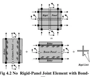
Fig 4.2 No Rigid-Panel Joint Element with Bond-Slip
The figure 4.2 show the plane rigid-panel joint element with bond-slip proposed by Limkatanyu. The joint element is consisted of a beam-panel, column-panel, and a rigid-link member. These two panels are assumed to be independent of each other and are connected together through a rigid-link member to eliminate spurious rigid body modes. The same rotation is imposed at each face of the joint element. The slippage of the rebars passing through the joint is explicitly included.
The rigid-panel assumption is reasonable when the shear deformations of the joint are negligible. This assumption is substantiated by the research conducted by Pantazopoulou and Bonacci, who carried out the database analysis of 143 specimens of exterior and interior beam-column joints tested over a span of 35 years in the US, Canada, Japan, and New Zealand. Pantazopoulou and Bonacci conclude that joints should be designed with sufficient hoop reinforcement so that their load carrying capacity exceeds that of the adjacent members.
4.4 Finite Element Modeling Geometry
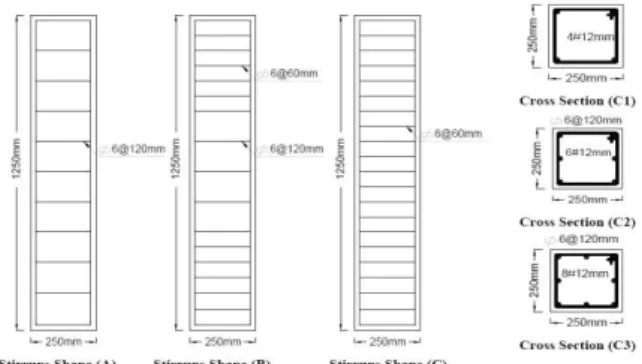
The details of tested columns were shown in Fig.4.3. Analyses were carried out on 10-columns specimens, where all columns had square cross-section with a 250mm side and length of 1250mm. Analyzed columns had main reinforcement with GFRP bars 4#12mm, 6#12mm, and 8#12mm, 4#16mm, and 4#18mm, and with steel bars 4#12mm.
The transverse reinforcement was ф6 mm closed
stirrups spread in 120mm, and 60mm, and characteristic strength of concrete columns 25, 30, and 35 N/mm2. The analyzed columns were divided into four different groups as shown on table 4.1. In this study, perfect bond between concrete and the reinforced bars was assumed. To provide the perfect bond, the link element for the reinforcing bars was connected between nodes of each adjacent concrete solid element, so the two materials shared the same nodes.
Fig no 4.3 Details of Reinforcement Of Tested Columns
4.5 Element Types
Extensive inelastic finite element analyses using the ANSYS program are carried out to study the behavior of the tested columns. Two types of elements are employed to model the columns. An eight-node solid element, solid65, was used to model the concrete.
The solid element has eight nodes with three degrees of freedom at each node, translation in the nodal x, y, and z directions. The used element is capable of plastic deformation, cracking in three orthogonal directions, and crushing. A link8 element was used to model the reinforcement polymer bar; two nodes are required for this element. Each node has three degrees of freedom, translation in the nodal x, y, and z directions.
The element is also capable of plastic deformation (ANSYS User's Manual).
4.6 Material Properties
Normal weight concrete was used in the fabricated tested columns. The stress-strain curve is linearly elastic up to about 30% of the maximum compressive strength. Above this point, the stress increases gradually up to the maximum compressive
strength, fcu, after that the curve descends into
softening region, and eventually crushing failure occurs at an ultimate strain. The input data for the concrete, GFRP, and steel (high grade and mild steel) properties are shown in Table.
Table 4.1 Input Data for The Concrete, GFRP, And Steel (Main Steel And Stirrups) Properties
4.7 Loading and Nonlinear Solution
The analytical investigation carried out here is conducted on 10-RC columns; all columns are raised in vertical position with by vertical load on top surface. At a plane of support location, the degrees of freedom for all the nodes of the solid65 elements were held at zero.
In nonlinear analysis, the load applied to a finite element model is divided into a series of load increments called load step. At the completion of each load increment, the stiffness matrix of the model is adjusted to reflect the nonlinear changes in the structural stiffness before proceeding to the next load increment. The ANSYS program uses Newton-Raphson equilibrium iterations for updating the model stiffness.
For the nonlinear analysis, automatic stepping in ANSYS program predicts and controls load step size. The maximum and minimum load step sizes are required for the automatic time stepping. The simplified stress-strain curve for column model is constructed from six points connected by straight lines.
The curve starts at zero stress and strain. Point No. 1, at 0.3f’c is calculated for the stress-strain relationship of the concrete in the linear range. Point Nos. 2, 3 and 4 are obtained from Equation (1), in
which εois calculated from Equation (2). Point No. 5
Fig.4.4 shows the simplified compressive axial stress-strain relationship that was used in this study
Fig no 4.4 Simplified Compressive Axial Stress-Strain Curve for Concrete
V.
INELASTIC ANALYSIS RESULTS
AND DISCUSSION
5.1 Experimental ValidationThe validity of the proposed analytical model is checked through extensive comparisons between analytical and experimental results of RC columns under compression load. Fig. 4 shows the theoretical and experimental load-deformation curve of tested columns from C1 to C8. The theoretical results from Finite Element Analysis showed in general a good agreement with the experimental values
5.2 Main Reinforcement Ratios
The theoretical load-deformation of columns C1, C2, C9, C3 and C10 which reinforced by GFRP reinforcement 4#12mm, 6#12mm, 4#16mm, 8#12mm and 4#18mm (0.723, 1.08, 1,286, 1.45 and 1.628 %) respectively; increasing GFRP reinforcement ratio leads to increase the toughness and ductility of tested columns. From Table 3, it can be seen that, ultimate loads, and ultimate strain C2, C9, C3 and C10 to C1 are (114,117,118&122%), and (109,115,115&119%) respectively.
The increasing of main reinforcement ratios with GFRP bars increase the ductility of cross section, so it has a significant effect on ultimate strain, and ultimate loads that the columns resist. Fig. 6 shows the effect of the main reinforcement ratios on the ultimate load that the columns resists, where the increasing of main reinforcement ratios from 0.723 to 1.2% has a significant effect on ultimate loads more than ratio from 1.2 to 1.62%.
5.3 Main Reinforcement Types
Fig. 7 shows the load-deformation of columns C1 and C4 which reinforced by GFRP and steel reinforcement with 4#12mm (0.723%); tested column with steel reinforcement has ductility more than column with GFRP reinforcement. From Table 3, it can be seen that, ultimate load, and ultimate strain of
C4 to C1 is 122.7 and 122.2 % respectively. Using steel as main reinforcement has a significant effect on the ultimate strain, and ultimate loads that the columns resist.
5.4 Transverse Reinforcement Ratios
The load-deformation of columns C1, C7 and C8; increasing of transverse reinforcement ratio leads to increase the toughness and ductility of tested columns. From Table 3, it can be seen that, ultimate loads, and ultimate strain of C7 and C8 to C1 are (110 &120 %) and (113&118 %) respectively. Fig. 9 shows the effect of the transverse reinforcement ratios in the column ends on the ultimate load that the columns resists, where the increasing of transverse reinforcement ratios has a significant effect on ultimate loads.
The load-deformation of columns C1, C7, C8 and C4, the increasing of stirrups with columns reinforced by GFRP increase the toughness and ductility of columns more than using steel bars with normal stirrups distribution, the behavior of column with steel bars C4 generate between the behaviors of C7 and C8.
5.5 Characteristic Compressive Strength of Concrete
From Table 3, it can be seen that, ultimate loads, and ultimate strain of C5 and C6 to C1 with (25, 30 &35N/mm2) are (119 &150 %) and (108&128%) respectively. Fig. 11 shows the load-deformation of columns C1, C5 and C6; increasing of characteristic strength of concrete has significant effect on the behavior of tested columns where increase toughness and ductility of tested columns. Fig. 12 shows the effect of the characteristic strength of concrete on the ultimate load that the columns resists, where the increasing of characteristic strength of concrete has a significant effect on ultimate loads.
5.6 Predicted Formula
Unfortunately, there was a lack of data about using FRP as reinforcement; the lack of a comprehensive database on FRP materials makes it difficult for the practicing civil engineer and designer to use FRP composites on a routine basis. Although a number of reviews have been published recently related to durability and test methods. The focus of each has been to summarize the state of knowledge in general without emphasizing or attempting to prioritize critical areas in which needs are the greatest for collection, assimilation, and dissemination of data (Karbhari et al. 2003).
VI.
CONCLUSION
The inelastic behaviour of 10 columns are investigated in the current study under the effect of increasing loading employing the inelastic FE analysis program ANSYS. Several parameters are investigated including the main reinforcement ratios, the main reinforcement types, the transverse reinforcement ratios, and the characteristic strength of concrete. The study focuses on the consequences of the investigated parameters on the deformation and ultimate resisting load. The conclusions made from this investigation are:
The theoretical results from Finite Element Analysis showed in general a good agreement with the experimental values
Increasing GFRP reinforcement ratio leads to increase the toughness and ductility of tested columns.
Increasing GFRP reinforcement ratio has a significant effect on ultimate loads.
Increasing GFRP reinforcement ratio from 0.723 to 1.2% has a significant effect on ultimate loads more than ratio from 1.2 to 1.628%
Tested column with steel reinforcement has ductility more than column with GFRP reinforcement.
Increasing of transverse reinforcement ratios in columns reinforced by GFRP bars increase the toughness and ductility of columns more than using steel bars with normal stirrups distribution.
Increasing of characteristic strength of concrete has significant effect on the behavior of tested columns reinforced by GFRP bars where it increases toughness and ductility of tested columns.
A new general formula was predicted from the experimental data, which was the average of data, as following
Where: N= axial load capacity of the reinforced concrete column with GFRP
f y = Yield strength of FRP
Ac= Cross section Area of concrete
Asc= Cross section area or main reinforcement
fcu = Ultimate compressive strength of the concrete
REFERENCES
[1]. V. M. Karbhari1, J. W. Chin, D. Hunston, B. Benmokrane, T. Juska, R. Morgan, J. J. Lesko7, U. Sorathia, and D. Reynaud, (2003) "Durability Gap Analysis for Fiber-Reinforced Polymer Composites in Civil Infrastructure", ASCE, August, 238-247 pp. [2]. Nicholas M., Rajan S. (2003) “The Fatigue of Fiber-Reinforced Polymer Composite
Structures State-of-the-Art Review” Civil &
Environmental Engineering, USF College of Engineering.
[3]. Halcrow W. and Partners Ltd; London,
England (1996) “FRP Concrete Structures”
Advanced Composite Materials In Bridges and Structures; M.M. B-Badry, Editor; Canadian Society for Civil Engineering, Montreal, Quebec.
[4]. OU J. and LI H., (2003) "Recent Advances of Structural Health Monitoring in Mainland China” The National Hi-Tech Research and Development Program (HTRDP), and practical engineering projects.
[5]. EL-Salakawy E. F., Kassem C., and Benmokrane B., (2003) "Construction, Testing and Monitoring of FRP Reinforced Concrete Bridges In North America" NSERC Chair, ISIS Canada, Department of Civil Engineering, Université de Sherbrooke, Sherbrooke, Québec, Canada J1K 2R1.
[6]. ACI Committee 440, (2006) “Guide for the design and construction of structural concrete reinforced with FRP bars,” ACI
440.1R-06, American Concrete Institute, Farmington Hills, MI.
[7]. Fardis M. N., Khalili, H., Concrete Encased in Fibreglass Reinforced Plastic. ACI Journal, 78 (6), 440-446 (1981).
[8]. Meier U., Bridge Repair with High Performance Composite Materials. Mater. Tech., 4, 125-128 (1987). AASHTO, 1989,
"Standard Specification of Highway Bridges, " Fourteenth Edition,
[9]. American Association of State Highway and Transportation Officials, Washington,DC. 2- Abdelrahman A.A., Tadros G., Rizkalla S.H., 1995, "Test Model for the First Canadian Smart Highway Bridge", ACI Structural Journal, Vol. 92, No.4, July-August, pp.451-458.
[10]. Abdelrahman A.A. and Rizkalla S.H., 1994,
"Advanced Composites for Concrete Structures" Technical Report, Fifth International Colloquium on Concrete in Developing Countries, Cairo, Egypt, January.
[11]. ACI Committee 318, 1995 "Building Code Requirements for Reinforced Concrete and Commentary (ACI 318-951ACI 318R-95)",
American Concrete Institute, Detroit, 369 pp.
ACI Committee 440, 1995, " State-of the-Art report on Fibre Reinforced Plastic (FRP) Reinforcements for Concrete Structures"