Using XML to Improve Frameworks Reuse
Juliana Alves Amaral*, Carlos Alberto Marques Pietrobon*,** Pontifícia Universidade Católica de Minas Gerais (PUC-MG)*
Universidade Federal de Ouro Petro (UFOP)**
Avenida Dom José Gaspar 500, Belo Horizonte, Minas Gerais, Brazil CEP: 30.535-610
*jamaral{jamaral, capietro}@pucminas.br ,**[email protected]
Abstract
This paper presents an approach to promote framework exchange through the use of XML standards. This exchange is quite important for developers’ teams who do not work at the same place neither the same environment, but need to collaborate in common projects. This paper combines the benefits of XML for defining, validating and sharing documents on the Web with the benefits of frameworks and object-oriented Unified Modeling Language (UML). UML-F-X, a extension of UML-F (an extension of UML for framework domain), is then proposed in this paper in order to take advantage of DTD concepts, reducing the semantic loss of framework-DTD mapping. By using standards for storing (UML) and sharing (XML) object-oriented frameworks, development teams using tools from multiple vendors can build and reuse applications in a distributed environment. The objective of this approach is to use the Web as a channel to exchange frameworks, stimulating then the use of this object-oriented technique among software engineers.
Keywords: framework, software reuse, UML, XML, Web-software engineering
1 – Introduction
New paradigms, techniques and software tools are being developed in order to meet increasing user needs, rising development and maintenance costs and greater complexity of new applications originated from diverse natures and specific domains.
The classic software development methods and tools have not been well succeeded in addressing these new challenges. Software development is usually expensive, takes more time than expected and presents quality problems. In order to solve such questions, several approaches to improve the software development process and to increase the product (software) quality has been studied. Some researches intend to identify ways of increasing the effectiveness of software engineers. Another approaches are related to software reuse [1] and object orientation, which is being presented as a powerful paradigm that can minimize some classic methods deficiencies
Nevertheless, it is necessary to overcome not only technical challenges but also managerial ones in order to achieve the plenty of benefits promised by object-orientation and software reuse. From the management point of view, software reuse practices require a high level of organization and discipline among software development teams. This discipline should be present at the creation, documentation and component testing phases. When the software process is then organized , a developer can locate, adapt and integrate existing components into a new specific application.
One of the greatest human obstacles related to software reuse is the opposition of this technique to the traditional “lonely programmer” stereotype. Some developers still prefer to work alone, without sharing better practices and writing illegible code and no documentation at all. Classical methods were not able to create a standardized work culture and the consequences is that nowadays software process still looks like more handicraft than engineer. Software reuse requires a medium-long term collaborative vision, because the results of a more organized way of working will bring benefits for the whole development team.
From the technical point of view, software has been developed in a distributed environment is composed of developers who use different tools to do their job. Therefore, a critical issue to reuse software is the need of integration between the tools used in software projects. This integration is done by mapping directly the data manipulated by one tool to the other tool format or to an intermediary representation that is understood by both tools.
Considering that people are working in several computing devices and in distributed environments, the Web can be used to connect them and enable a collaborative development. These integration among tools can be achieved by using XML (Extensible Markup Language). XML is fast emerging as the dominant standard for representing data on the Web and have been proposed as the language for data exchange between applications.
Besides the classic methods problems and the technical and managerial barriers, another aspect is the preservation of semantics during the mapping process. When the conversion from one model to another is being made, all information necessary to rebuild the original model should be provided. None of the modeling elements could be lost.
Some studies in the Web-based software engineering area have pointed out the need of integration between XML proposal and metamodel representation. By using standards for modeling (UML) and sharing (XML) object-oriented frameworks, development teams using tools from multiple vendors can build and reuse applications in a distributed environment.
In this article, a proposal that integrates frameworks domain with markup languages domain will be presented. Therefore, the main objective is to specify a way of using XML documents to promote conceptual framework artifacts exchange between tools. This work considers framework as a powerful technique to reuse software. According to [2] notation, UML-F will be used to describe frameworks.
Furthermore, an extension of UML-F, called UML-F-X, will be proposed, providing a suitable representation of frameworks into XML schemas. This UML-F extension is built on the existing extension mechanisms defined by UML itself. This extension needs to be well defined in order to reduce the semantic loss during the framework-XML schemas mapping process.
2 – Frameworks as Reuse Mechanisms
Despite the advance of technology, software development still continues to be a complex process. Software products in general present defects, cost more than expected and are deployed later than the original schedule. Software reuse is an approach to increase productivity and software quality. Nevertheless, reutilization is not an easy task. For [3], the increasing diversity of hardware and software architectures makes software reuse even more difficult.
An architectural basis for component development can minimize some questions associated with software reuse. According to [4], the problems of building complex information systems are related not only with algorithms and data structure, but also with architecture. Software architecture encompasses the description of the elements that belong to the system, the existing interfaces between these elements and the patterns to guide the system composition. Thus, software architecture provides a level of abstraction that helps developers to understand the system behavior [5].
A framework describes the architecture of an object-oriented system; the kind of objects in it, and how they interact. [3] describe framework as the skeleton of an application that can be customized by an application developer. By using frameworks, it is possible to model in a generic manner a family of similar applications. Framework is a reuse technique that is based on three object-oriented features: data abstraction, polymorphism and inheritance. Therefore, framework is one of the most accepted proposals for software reuse.
According to [6], a framework is formed by hot spots and frozen spots. The frozen spots define the global architecture of a system, its basic components and the relationships between them. This structure stays the same (frozen) in each instantiation of a framework. On the other hand, the hot spots are specific parts of each system and they are projected to be generic enough to be adapted according the needs of particular applications. [7] define hot spots as points of predefined refinement, where specialization takes place. The specialization of hot spots requires the definition of additional classes in order to override methods and/or object configurations based on components already provided by the framework. Hence, frameworks takes advantage of previous knowledge and effort of experienced developers in order to avoid rework during the creation of common solutions to similar applications.
3 – UML and Frameworks
[8] considers UML as a link between Software Engineering and document design, because it is possible to design OO software with the necessary XML structures. For [9], UML is a metamodel for software development. A metamodel, also called metadata model, defines the structure and the meaning of data. If development tools share the same metamodel, all data will be understood and used.
Even though [2] describes the design of frameworks with UML, the exchange of frameworks between tools has not been deeply studied yet. The focus of [2] work is related to the representation of frameworks semantics with UML.
It is necessary to specify frozen spots and hot spots during the framework modeling. Frozen spots can be modeled with the UML basic features. Unlike frozen spots, hot spots requires UML extensions for its correct specification. This can be made by using the UML extension mechanisms [10]: stereotypes, tag values and constraints.
that have a well defined interface, but whose implementation varies for each instantiated application. Extensible classes are classes that may have their interfaces extended during framework instantiation. Extensible interfaces are abstract classes that allow the creation of concrete subclasses during the framework instantiation. These new classes are called application classes, which exist only in framework instances. All three kinds of hot spots may be static (do not require runtime instantiation) or dynamic (require runtime instantiation).
In UML-F, framework hot spots are represented in a class diagram with the following tag values [11]: variable, extensible, static, dynamic, incomplete e appl-class. Variable is
applied to the methods of a class and represents variable methods hot spot. Extensible is applied to a class and represents extensible classes hot spot. Incomplete tag is applied in the generalization/specialization and represents extensible interface hot spot. The keyword incomplete already exists in UML as a constraint extension mechanism. Static and dynamic tags complement hot spot notation, indicating whether the hot spot requires runtime instantiation or not.
4 – Information Exchange through XML
The XML [12] is a standard approved by W3C (World Wide Web Consortium) to be a data interchange format for the Web. Validation of a XML document and verification of its grammar correctness require a clear definition of the document structure (schema).
XML community has developed schema languages to describe document structure [9]. DTD (Document Type Definition) is the original schema language included in XML 1.0 specification [12]. According to [13], DTD is a document free context grammar that can be also used as a schema for the data represented by the document. An alternative for DTD is XML Schema, presented by W3C and recommended to become a standard [14].
XMI (XML Metadata Interchange) has specified the mapping of UML models to DTDs and should incorporate sooner the mapping to XML Schemas. The main objective of XMI is to permit, in heterogeneous and distributed environments, metadata exchange among tools and between tools and MOF-based metadata repositories [15].
XMI carries out the mapping from MOF (Meta Object Facility) metamodels to DTDs and from MOF metadata to XML documents. Because of the alignment between UML and MOF concepts, XMI becomes a practical manner of implementing the UML-XML mapping.
According to [15], XMI specifies the requisites that a XML DTD, called XMI DTD, should follow, making possible to verify, through XML validation, the metamodel information contained in XMI DTD. The possibility of validation by a XML processor takes out the responsibility of import and export programs, making easier data exchange.
5 – Related Works
There were some proposals for UML mapping to XML (DTD or XML Schema) and also for the opposite way. On the next proposals, UML is used because its diagrams are able to model XML structures in a high conceptual level of abstraction. Nevertheless, these proposals present limitations on UML-F representation. These proposals will be detailed as follows.
XMI [16] is a OMG proposal to automatically generate DTDs from MOF compatible models and XML documents from metadata.
is mapped to a XML structure (DTD or XML Schema) and the object diagram is mapped to a XML document. A third approach is presented by [8], who propose the conversion of class diagrams into DTDs. It is done by extending UML with stereotypes that guide the UML mapping to DTD constructors.
[9] and [8] have studied the markup language domain (XML), adding information from this language to UML. In turn, [2] focus framework domain, incorporating structures from this domain to UML.
Another proposal of UML models conversion to DTD has been developed by [17]. The proposal presented by [18]is quite different, because UML semantic richness is restricted into a subset called schema model. These restrictions eases the definition of rules and the mapping process itself. This proposal differs from [9], [17] and [8] studies, because [18]does not extend UML with stereotypes.
The approach proposed by [19] differs from the previous ones because the input is not a class diagram, but an XML application with a DTD. In fact, the class diagram is the output. The proposal presented by [20] has the same output, but the input is XML Schema.
In all of the proposals presented above, the methods of the UML class diagram are not included in the mapping process. This work intends to include methods signatures in the UML-XML mapping. A method signature contains the name of the method, its parameters and the type of return value. The mapping of method signature and its tag values is sufficient to represent semantically a framework designed in UML-F.
Furthermore, the previous proposals does not consider a particular application domain or software structure. These proposals map the construct elements (classes, attributes and so on) without worrying about the domain nature represented by the model.
In this article, the mapping input will be a framework described in UML-F-X. The approaches presented in this section does not contain the necessary features to map directly UML-F, because the essential components of UML-F are based on methods and extension mechanisms, more precisely on tag values. So, it is necessary to create new UML classes to explicitly represent the UML-F specific domain. These new classes will be created by using the own UML extension mechanisms. UML-F extension makes it possible to map UML-F to XML without loosing framework semantics.
The option of extending UML has been chosen because most of the proposals presented before use UML extensions. [9] emphasizes that generating code from UML for various languages such as Java, C++, SQL databases or XML schemas often requires additional information that guides the code generation syntax or process.
6 – UML-F-X: an extension of UML-F for XML mapping
Figure 1. Mapping process
In order to minimize semantic losses during the mapping from frameworks to XML schemas, [9] approach will be adopted instead of XMI proposal [16]. XMI production rules only allow the generation of relaxed DTD and not strict DTD, which are quite useful when designers want a better representation of semantic constraints that exists on the model like multiplicity constraints.
In this article, the UML profile mechanism proposed by [9] is used to extend UML-F. A UML profile defines a set of stereotypes that extends UML basic constructors with new meanings and properties. Each UML profile stereotype can contain tag values and constraints. The main objective of a UML profile is to guide the generation of XML schemas (DTD and XML Schema) from UML class diagrams. This article focus the representation of UML-F-X semantics through UML profiles, because the procedures to generate XML schemas from UML profiles has already been defined.
Among the UML profiles presented by [9], this work adopts <<enumeration>> profile, because it is sufficient to represent UML-F semantics and it is a standard element of UML specification. According to [10], <<enumeration>> is applied to a class and specify an enumerated type, including its possible values as a set of identifiers.
UML-F semantics incorporate tag values to extend UML class diagram. Among the defined tag values, appl-class, extensible and incomplete are applied to classes, variable is applied to methods and dynamic and static are applied to both classes and methods. In this article, UML-F tag values are represented by the <<enumeration>> UML profile. Therefore, the proposal is related to create new classes with the <<enumeration>> stereotype.
6.1 Mapping Scope
In the mapping from UML model to XML vocabulary, the following dimensions can be observed: from object instances to XML document and from class definition to XML schemas. These options are strongly related because generated XML document is validated by the XML schema. Furthermore, the DTD generation depends on UML model semantics.
This section presents the necessary features to extend UML-F and the procedures to specify an extended UML-F model, facilitating then the XML DTD generation. This UML-F extension will be called UML-F-X where the letter X stays for the appliance of XML standards.
Application
Framework UML-F
Framework UML-F-X
The objective of this article is related with the exchange of design structures that specify frameworks. Framework means here a conceptual model, thus the focus of this article is model exchange and not data exchange. Model exchange is placed on an abstraction level higher than data exchange. This issue becomes clearer when the layers of MOF architecture (adopted by OMG) are analyzed.
The MOF model specifies general guidelines to sustain a minimal standardization during metamodel creation. According to [16], the MOF model defines a common abstract syntax for metamodel definition, being a model to metamodels. So, MOF can be described as a meta-metamodel.
There is a close alignment between MOF meta-modelling concepts with UML modeling concepts [16]. Not only UML but also MOF agree with the paradigm of object orientation.
As shown in Figure 2, the MOF architecture has four layers: M0,M1,M2 and M3. One layer is always an abstraction of the layer below it. UML and UML-F-X (M2 layer) can be understood as MOF instances (M3 layer). UML-F-X is placed on M2 layer as a MOF metamodel, because it follows the specification of MOF constructors. According to [10], UML extension mechanisms are capable of extending UML language in a controlled manner, staying loyal to UML principles. Therefore, it is right to describe UML-F-X as a MOF metamodel.
Figure 2 – MOF-layer architecture [adapted from [9]]
The data level (M0 layer) is the physical level which has the lowest degree of abstraction. In this level, the models specified in M1 layer are implemented, using the language defined in M2 layer.
XMI is able to exchange metamodels between tools because it establishes production rules for DTD generation. Besides that, XMI defines production rules to code and decode M1-layer models to and from XML documents.
XMI is used to produce a DTD from UML, because UML metamodel is a MOF instance. XMI can be also applied to generate XMI documents (XML documents that obey XMI rules) from a UML model validated by a DTD.
MOF Model
UML or UML-F-X Meta Model
XML Modelo Meta Model
UML or UML-F-X
Model XML Schemasor DTDsorou
Objects XML Documents
M0 Layer M1 Layer
M2 Layer
According to figure 3, the origin of the mapping presented in this work is a framework model defined in UML-F-X. This model is placed on M1 layer because it is an instance of UML-F-X metamodel (M2 layer). The mapping output is XML DTD (M2 layer). The DTD generation from UML-F-X models is possible because XMI defines DTD generation rules for any metamodel that is compatible with MOF, like UML-F-X is.
Figure 3 – Mapping from UML-F-X to DTD by using XMI
According to XMI specification, XMI rules can be applied to map a metamodel (M2 layer) to DTD. [9] describes a different point of view from the mapping proposed by XMI, where these same rules can also be used to map a model (M1) to XML schemas. This approach is valid because a model developed according to metamodel rules can be interpreted as a metamodel. So, there is a shift from M1 layer to M2 layer. This shift has been specified on XMI specification, as follows:
“While the typical use of MOF involves a four layer metadata architecture, there are situations in which only three layers are required. In such cases, the meta-layers are shifted and MOF model effectively becomes the metamodel for operational data. XMI can then be used as an data interchange medium.” [16], page 4-43
The problem of applying XMI rules in order to generate DTD is solved by an adaptation of a trick proposed by [9]. The trick consists of interpreting the UML model as an instance of MOF model.
Applying [9] approach in this work, it is possible to interpret a UML-F-X model (M1 layer) as a metamodel and then map it to DTD following XMI rules. In analogous manner, an instance of a model (M0 layer) can be interpreted as a model (M1 layer) and then mapped to XML documents. This article will focus the generation of XML structures instead of XML documents. The mapping process is presented by figure 4, which has only three layers.
MOF Model
Objects
XMI Document for exchange between
UML tools UML-F-X Model
Produced according to XMI
DTD UML-F-X
Metamodel
Produced according to XMI
Figure 4. UML-F-X mapping to DTD, following XMI (adapted from [9])
6.2 – UML-F-X Metamodel
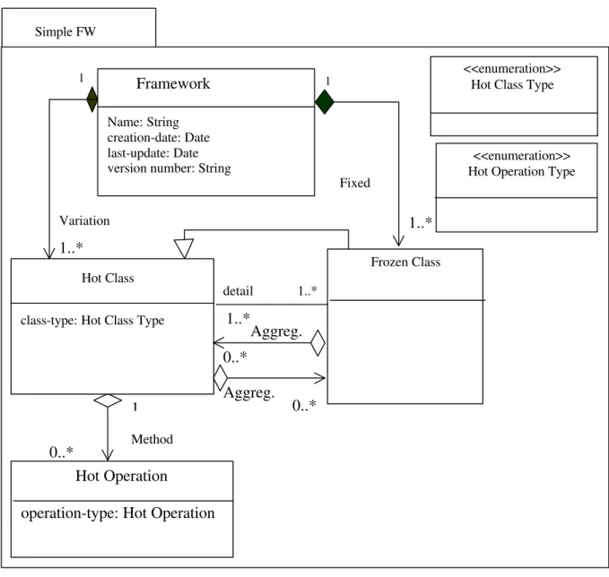
In order to perform the mapping from UML-F-X to DTDs, this article proposes a simplified metamodel to guide the developers who intend to create a framework or to convert their UML-F frameworks to UML-F-X. This issue is addressed by the creation of a UML-F-X metamodel. Once the conversion is done, the [9] approach can be employed to generate strict or relaxed DTDs.
In this metamodel, only the components (attributes, methods, classes) that are necessary in the definition of UML-F-X will be specified. For simplicity reasons, the features related to frozen classes will not be detailed, because the focus is on framework variation points.
The UML-F-X metamodel has a Simple FW package to organize framework elements.
A class called Framework represents the framework itself and contains the following
attributes: name, creation-date, last-update and version-number. These attributes are relevant for version control purposes. The Hot Class models the hot spots, which are important
elements of this metamodel. Frozen spots represent framework fixed points and will not be detailed in this metamodel.
The Hot Class class has the class-type attribute that is associated to the Hot Class Type class, which is labeled with the <<enumeration>> stereotype. Its list of values contains
the possible combinations of tag values for a hot spot class, as follows: appl-class, extensible, extensible, static, extensible dynamic, incomplete, incomplete static, incomplete dynamic, incomplete extensible, incomplete extensible static, incomplete extensible dynamic and null.
The Hot Class has zero or many operations that are variation points, which are
represent by Hot Operation class. This class has the operation-type attribute that is associated
to the Hot Operation Type class stereotyped by <<enumeration>>. The list of possible values
for Hot Operation Type class is the following: variable, variable static, variable dynamic and
null.
The UML-F-X metamodel also requires the definition of relationships in order to specify how the various framework elements are related. The relationship between Hot Class, Frozen Class and Framework is represented by a composition, which is an specific type of
aggregation where the part has the same lifetime of the whole. There are also both ways inheritance, aggregation and association relationships between Hot Class and Frozen Class.
For simplicity reasons, the UML-F-X metamodel does not contain the definitions that are already described by the UML metamodel, such inheritance between classes and attributes related to method signatures.
Produced according to XMI
DTD UML-F-X Model
Produced according to XMI
XML Document UML-F-X Objects
Instance of
MOF Model Instance of
Figure 5 describes the UML-F-X simplified metamodel with the features presented before.
Figure 5 - UML-F-X simplified metamodel
In Figure 6, there is an example of a part of a UML-F model used by [2]. This model describes a framework for applications related to educational area and variation points are represented by tag values.
Simple FW
<<enumeration>> Hot Class Type
<<enumeration>> Hot Operation Type
1..* 1
Variation
1
1..* Fixed
Framework
Name: String creation-date: Date last-update: Date version number: String
0..*
1 Method
Hot Operation
operation-type: Hot Operation Hot Class
class-type: Hot Class Type
Frozen Class
0..* Aggreg. 0..*
Aggreg. 1..* 1..*
Figure 6 - UML-F class diagram [2]
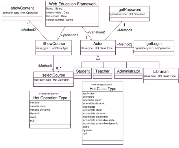
Figure 7 represents the UML-F-X version of figure 4 UML-F model. The UML-F-X metamodel is used as a guideline for this conversion.
Figure 7 - UML-F-X class diagram ShowCourse
{Extensible,dynamic} selectCourse() {variable, dynamic} showContent()
Actor
{static} getLogin()
getPassword()
Student Teacher Administrator {appl-class}
Librarian {incomplete}
selectCourse operation-type : Hot Operation
Hot Class Type appl-class extensible extensible static extensible dynamic incomplete incomplete static incomplete dynamic incomplete extensible incomplete extensible static incomplete extensible dynamic static
dynamic null
<<enumeration>>
Hot Operation Type variable variable static variable dynamic dynamic static null <<enumeration>>
Student Teacher Administrator Librarian class-type : Hot Class Type showContent
operation-type : Hot Operation
ShowCourse class_type : Hot Class Type 1 +Method2 1 0..* * +Method1 0..* * Web-Education-Framework Name : String
creation-date : Date last-update : Date version number : String
1 +Variation1
1
getLogin operation-type : Hot Operation Actor
class-type : Hot Class Type 1 +Variation2 1 1 +Method2 1 getPassword operation-type : Hot Operation
1 +Method1
6.3 – DTD Mapping
This article focus the semantic definition of UML-F-X, because there are available tools that generate automatically DTD and XML Schema from UML models. As [9] approach is adopted for framework-XML mapping, the tool suggested by [9] was chosen for DTD generation. This software is IBM XMI Toolkit that was developed by alphaWorks, who is a workgroup dedicated to emerging technologies. This tool is available for download at [21]. Besides generating DTDs from UML models designed with Rational Rose (.mdl files), the tool uses XMI standard to perform the both ways conversion between UML and Java.
Next, there is an example of a relaxed DTD related to the class ShowCourse (figure 5)
mapping.
<!--CLASS: ShowCourse -->
<!ELEMENT ShowCourse.class-type EMPTY>
<!ATTLIST ShowCourse.class-type xmi.value (appl-class | extensible | extensible static | extensible dynamic | incomplete | incomplete static | incomplete dynamic | incomplete extensible | incomplete extensible static | incomplete extensible dynamic | null)
#REQUIRED>
<!ELEMENT ShowCourse.Method2 (showContent)*> <!ELEMENT ShowCourse.Method1 (selectCourse)*>
<!ELEMENT ShowCourse (ShowCourse.class-type | ShowCourse.Method1 | ShowCourse.Method2 | XMI.reference) * >
<!ATTLIST ShowCourse
class-type (appl-class | extensible | extensible static | extensible dynamic | incomplete | incomplete static | incomplete dynamic | incomplete extensible | incomplete extensible static | incomplete extensible dynamic | null) #IMPLIED
Method1 IDREFS #IMPLIED Method2 IDREFS #IMPLIED %XMI.element.att;
%XMI.link.att; >
7 – Conclusion and Future Work
One of the contributions of this article is the proposal of UML-F-X to model frameworks that need to be exchanged trough the Web. In this article, the mapping process from UML-F-X to XML DTD is specified by defining a UML-F-X metamodel and applying [9] mapping approach. In future work, XML Schema can be the output of mapping process.
An interesting aspect of this article is that it can be considered a Web complement of [11] thesis developed at PUC-RJ Software Engineering Laboratories. The development of joint researches and the cooperation between groups of different universities are appropriate forms of avoiding redundant work and optimizing resources.
The benefits of using XML to define, validated and share documents can be combined with the benefits of UML to specify, visualize and document information systems. Distributed software teams working in different environment require an intense exchange of data and models between applications, tools and repositories.
The increasing impact of Web technologies on the software development process has produced a synergy between researches related to Web standards and works concerning software engineering. The consolidation of XML on the Web and of UML on system analysis field has accelerated even more this synergic process. This sum of efforts is very positive because it avoids reworks and studies in opposite directions.
Framework exchange trough XML is situated on this interdisciplinary field between Web and software engineering. This field has proved to be very promising to the development of a software engineering approach that is aligned with the present needs of distributed environments. In this context, the increase of framework exchange opportunities can contribute to a higher level of reuse, producing significant gains of productivity and software quality.
References
[1] JACOBSON, Ivar; GRISS, Martin; JONSSON, Patrik. Software Reuse - Architecture, Process and Organization for Business Success. Addison Wesley,1997
[2] FONTOURA, M.; PREE, W.; RUMPE, B. UML-F: A Modeling Language for Object-Oriented Frameworks. ECOOP 2000, Springer, 63-82, Cannes, France, 2000.
[3] FAYAD, M.; SCHMIDT, D.; JOHNSON, R. Building Applications Frameworks. John Willey & Sons,1999
[4] BARBOSA, Álvaro C. Pereira; LUCENA, Carlos José P. Integração de Frameworks de Software. Monograph, PUC-RJ, Brazil, 2000.
[5] MONROE, Robert; KOMPANEX, Andrew; MELTON, Ralph; GARLAN, David. Architectural Styles, Design Patterns and Objects. IEEE Software, Janeiro de 1997, p.43-52 [6] PREE, W. Design Patterns for Object-Oriented Software Development. Addison-Wesley,1995.
[7] PREE, W; POMBERGER, G.; SCHPPERT, A; SOMMERLAND, P. Active Guidance of Framework Development. Software – Concepts and Tools. Springer-Verlager, 1995, p. 94 – 103.
[8] CONRAD, R.; SCHEFFENER, D.; FREYTAG, J. XML Conceptual Modeling using UML. ER 2000, Salt Lake City, Utah, USA, October 9-12, 2000
[9] CARLSON, D. Modeling XML Applications with UML. Addison Wesley,2001.
[10] BOOCH, Grady; RUMBAUGH, James; JACOBSON, Ivar. The Unified Modeling Language User Guide. Addison Wesley,1998.
[11] FONTOURA, Marcus. A Systematic Approach to Framework Development. Doctoral
thesis, PUC-RJ, Rio de Janeiro, Brazil, 1999.
[12] The World Wide Web Consortium. Extensible Markup Language (XML) 1.0, February 1998. http://www.w3.org/TR/REC-xml
[13] ABTEBOUL, Serge, BUNEMAN, Peter, SUCIU, Dan. Data on the Web: From Relations to Semistructured Data and XML. Morgan Kaufmann, October, 1999.
[14] The World Wide Web Consortium. XML Schema Part 0: Primer, 2 May 2001.
[15] CHANG, Dan; HARKEY, Dan. Client /Server Data Access with Java and XML. John Willey & Sons,1998.
[17] KIMBER, W. Eliot; HEINTZ, John. Using UML to define XML document types. Markup Languages: Theory & Practice 2/3 (Summer 2000),pages 295-320
[18]SKOGAN, David. UML as a schema language for XML based data interchange. In Proceedings of UML'99, 1999. http://www.ifi.uio.no/davids/papers/Uml2Xml.pdf
[19] JENSEN, M.; MÜLLER, T.; PEDERSEN, T. Converting XML Data to UML Diagrams for Conceptual Data Integration. In CAiSE*01 DIWeb. Interlaken, 2001
[20] BOOCH, Grady; CHRISTERSON, Magnus; FUCHS, Matthew; KOISTINEN, Jari. UML for XML Schema Mapping Specification. Addison Wesley, August, 1999.

![Figure 2 – MOF-layer architecture [adapted from [9]]](https://thumb-eu.123doks.com/thumbv2/123dok_br/15696217.628150/7.892.106.786.569.900/figure-mof-layer-architecture-adapted-from.webp)

![Figure 4. UML-F-X mapping to DTD, following XMI (adapted from [9]) 6.2 – UML-F-X Metamodel](https://thumb-eu.123doks.com/thumbv2/123dok_br/15696217.628150/9.892.114.710.150.338/figure-uml-mapping-dtd-following-xmi-adapted-metamodel.webp)