Abstract— In software engineering, a software pattern is a reusable solution to solve recurring software design problems. Traditionally, suitable patterns are identified by software designers to satisfy a set of requirements. A part of appropriate patterns is then applied to a recurring software design problem. However, the existing software patterns part has to be properly integrated to specific design problems. Therefore, the introduction of formalization is required to describe this integration accurately. In this paper, we propose a framework of UML class diagrams and software patterns integration prepared for formal specification to solve different software designer’s experiences. The integration rules in this formal framework is intended to complement existing textual and graphical descriptions in order to eliminate the ambiguity of class diagrams with software patterns integration. A case study of our approach is illustrated in a purchase order system.
Index Terms— software patterns, UML class diagrams, software design, formal specification.
I. INTRODUCTION
The conventional software development starts with application domains modeling with software models such as UML models [1]. UML class diagrams are a widely used technique for modeling the static structure of a software model which is created by software designers. Therefore, software designers need to fully understand the problem domain in order to design such software models. Whereas, a part of solving design problem in software application is collected as software patterns those can be applied during software modeling. There are several kinds of patterns that can be applied to software models. In this paper, the focus is on archetype patterns which are used to describe possible software models. The archetype patterns are always at a higher level of abstraction than normal analysis class that can be adapted to specific business domains [2].
Many researches show reused patterns have been promoted. For example, [3] focused on the use of patterns for business processes and also the derivation of UML classes from the process patterns manually. [4], [5] tried to select patterns in different patterns to software models by expert systems such as ontology. As an aspect of formal specification of class diagrams and state diagrams in simple notation are based on
Manuscript received December 16, 2009.
W. Rungworawut is with the Information Systems Engineering Laboratory, Department of Computer Engineering, Chulalongkorn University, Bangkok 10330 Thailand (phone: +66 2 2186991; fax: +66 2 2186955; e-mail: [email protected]).
basic mathematics and predication logic has been proposed in [6]. Similarity to the approach in [7], a class diagram representation and software patterns have been defined with a suggestion of using a rule-based method to match design patterns into a UML model. However, these researches have not discussed how to apply software patterns to UML class diagrams in a formal specification accurately. The difference of our approach is trying to fabricate precise integration rules between UML class diagrams and software patterns in a form of a formal specification.
In this paper, we present an overview of a framework for the integration of software patterns applying to specific design problem as UML class diagrams. The main objective is to create the integration rules based on the basic mathematics and the predicate logic in order to eliminate ambiguity and allow rigorous reasoning about the integration of class diagrams with software patterns. These rules are easily used as criterion to apply in the information such as attributes, methods and associations, which are extracted between UML class diagrams and software patterns. Our framework will help software designers to construct a software model as UML class diagrams by adding these details to classes using software patterns.
The overview of framework for UML class diagrams and software patterns integration is proposed in Section II. The definition of UML class diagrams and software pattern is given in Section III. And Section IV is the description of integration rules. Section V shows the case study followed by integration rules used in this case and also the discussion about the case study. Last but not least, our future works are concluded in Section VI.
II. OVERVIEW OF FRAMEWORK
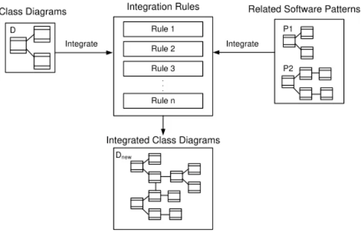
The overview of framework, software designers have knowledge in design software to create classes in a class diagram (D) for a particular design problem. These classes in a class diagram may be satisfied with a set of requirement but they may be not sufficient to derive the possible class diagram. However, software designers need to query existing solution of experts during a design decision such as looking for software patterns. A software pattern has a name corresponding to the document solution as problem domain name that is unique within a pattern catalog. Therefore, those software patterns are selected by searching problem domain names. The problem domain name is a meaningful name that will be a part of the shared design vocabulary [8]. Mostly software pattern description formats also contain an implicit or explicit related software patterns section [9], [10]. For
A Framework for UML Class Diagrams and
Software Patterns Integration
example, prototyping a class diagram (D) has labeled a problem domain name. The problem domain name is queried in software pattern catalogs that collected various software patterns. Software patterns are related to class diagram (D), which exactas software pattern P1 and P2. The class diagram (D) and those software patterns P1 and P2 are appropriate integrated by criteria selection from integration rules. These integration rules apply to a single new class diagram (Dnew) in
Fig. 1. Class Diagrams
P1 P2
Related Software Patterns
D
Integrated Class Diagrams
Integrate Integrate
Dnew
Integration Rules
Rule 1 Rule 2 Rule 3 Rule n
. . .
Fig. 1 Overview of UML class diagram and software pattern integration framework.
III. FORMAL SPECIFICATION OF INTEGRATION RULES
A. Class Diagram
A Class diagram relations are modeled by mean of labeled relationship between classes. Hence, D represents the set of a class diagram.
D = (C, R)
Class (C) is a set of classes and CN represents the infinite set of class names.
C = {ci (cn, A, M) | i ℕ, cn CN}
Thus, a class ci is a tuple ci = (cn, A, M) where,
cn name of ci.
A a finite set of attribute of ci.
M a finite set of operations of ci.
Each of the item x in the tuple ci is denoted ci.x. For
example, ci.cn denotes the name of ci or ci.A denotes the set
of attributes A of ci, etc.
Let us consider two infinite sets of AN and MN, which respectively represent the set of attribute name and method name. Given a set of basic types B includes integer, string, float, double, etc.
A is a set of attributes. An attribute ai consists of a method
name an, where an AN and a attribute type is a basic type bi.
A = {ai(an, bi) | i ℕ, an AN, bi B CN}
Each of the item x in the tuple ai is denoted ai.x. For
example, ai.an denotes the name of ai.
M is a set of methods. We denote a method signature by notation ms1, …, msnms, where ms1, …, msn, ms B CN. A method mi: ms1, …, msn ms consists of a method name m, where m MN and a method signature ms1, …, msn ms.
M = {mi: ms1, …, msn ms | i ℕ , mi MN, ms B
CN}
Relations (R) Let R is a set of relationship between classes. R = {ri (ci, cj, S) | i,j ℕ}
Thus, a relation ri is a tuple ri = (ci, cj, S), where ci, cj are
two classes, and S = {s} is a set of description of the relationship between ci and cj. The description of an
association s = (t, L, g) where t is enumeration of types includes association, inheritance, aggregation, composition etc. L is a set of labels and g is a directional flag which is either unidirectional, represent by ci cj, or bidirectional
represented by ci cj as follows,
String information users
Role a pair (r1, r2) also information users
Multiplicity a pair (v1, v2) by vi is of the form li..ui where li,
ui≥ 0 such as 0..2, 1..*, 0..* etc.
Fig. 2 A pair of relations of class diagram. The definition of all classes and relationships can be illustrated by an example with consideration the UML class diagram shown in Fig. 3.
Fig. 3 Example of a part of class diagram (D). As Fig. 3, set of flight class diagram is represented by DFlight = (C, R) ,by set of classes C is
C= {c1(Flight, AFlight, MFlight), c2(Plane, APlane, Mplane)}
AFlight= { a1(flightNumber, Integer),
a2(departureTime, Date),
a3(flightDuration, Minutes),
a4(departingAirport, String),
a5(arrivingAirport, String) }
Class c
i Multiplicity v1 Multiplicity v2String
Class c
jMFlight= { m1:delayFlight() Minutes,
m2:getArrivalTime() Date}
APlane= { a1(airPlaneType, String),
a2(maximumSpeed, MilePerHours),
a3(maximumDistance, Miles),
a4(tailId, String) }
Mplane=
R = {r1(c1,c2, S)}
S = (association, L, c1 c2)
L= (null, (assignedFlights, assignedPlane), (0..*, 0..1))
B. Software Pattens
Software patterns are class diagram patterns which consist of classes and relations between classes in a class diagram pattern. Hence, P represents the set of class diagram patterns.
P = (CP, RP)
Class Patterns (CP) is a set of classes in a class diagram pattern and CPN represents the infinite set of class pattern names.
CP = {cpi (cpn, AP, MP) | i ℕ, cpn CPN}
Thus, a class cpi is a tuple cpi = (cpn, AP, MP)
where,
cpn name of cpi.
AP a finite set of attribute of cpi.
MP a finite set of operations of cpi.
Therefore, let us consider two infinite sets of ANP and MNP, which respectively represent the set of attribute name and method name. To similar, given a set of basic types B in class diagram (including integer, string, float, double, etc).
AP is a set of attributes in a class pattern cpi. An attribute
api consists of a method name anp, where anp ANP and a attribute type is a basic type bi.
AP = {api(anp, bi) | i ℕ, anp ANP, bi B CNP}
MP is a set of methods in a class pattern cpi. We denote a method signature in a class pattern by notation msp1, …, mspn msp, where msp1, …, mspn, msp B CNP where mp MN and a method signature ms1, …, msn ms.
MP = {mpi: msp1, …, mspn msp | i ℕ , mpi MNP,
msp B CNP}
Relations (RP) Let RP is a set of relationship between classes in a class diagram pattern.
RP = {rpi (cpi, cpj, SP) | i,j ℕ }
Thus, a relation rpi is a tuple rpi = (cpi, cpj, SP), where cpi,
cpj are two classes in a class diagram pattern, and SP = {sp} is
a set of description of the relations hip between cpi and cpj.
The description of an association sp = (t, L, g) where t, L and g is similar to set s of class diagram (D).
IV. INTEGRATION RULES
The definitions of class diagram and software patterns are used for integration rules. This paper presents an example three of integration rules as follows,
A. Integration rule 1
Let ci is a class in class diagram (D) and P1 is a software
pattern that is related to domain in class diagram of ci. Thus,
ci will be integrated to P1 and moved details (i.e. attributes,
methods) in cpi of P1 to original ci followed definition of set
in Rule 1.
Rule 1 If ci.cn = cpi.cpn by iℕ, ci D, cpi P1.
Then ci.A = ci.A cpi.A and ci.M = ci.Mcpi.M by iℕ.
Example of Rule 1
c1
a1
a2
m1
cp1
ap1
ap2
mp1
=
c1
a1
a2
ap1
ap2
m1
mp1
P1
Fig. 4 Example of integration rule 1.
For example, a class c1 is relevant to cp1 in software pattern
P1. Thus, the result in Fig. 4 shows new c1 that is added
details in attributes and methods such as ap1, ap2 and mp1
from cp1 respectively.
B. Integration rule 2
Let ci is a class in class diagram (D) and P1 is a software
pattern that is related to domain in class diagram of ci. But
multiple classes is related to a class cpi in software pattern.
Thus, ci will be integrated all related to cpi in P1 and moved
details (i.e. attributes, methods) in all cpi of P1 to original ci
followed definition of set in Rule 2.
Rule 2 If ci.cn = cpi.cpn and ri.cpi = (cpi, cpj, S) by i, j ℕ, ci
D, cpi P1.
Then ci.A = ci.A cpi.A and ci.M = ci.M cpi.M and ri.ci
Example of Rule 2
=
c1
a1
a2
ap1
ap2
m1
mp1
c1
a1
a2 m1
cp1
ap1
ap2
mp1
cp2
ap1
ap2
mp1
cp3
ap1
ap2
mp1
cp2
ap1
ap2
mp1
cp3
ap1
ap2
mp1
P1
Fig. 5 Example of integration rule 2.
For example, a class c1 is relevant to cp1 in software pattern
P1 and cp1 is related to cp2 and cp3. Thus, the result in Fig. 5
shows new c1 that is added details in attributes and methods
such as ap1, ap2 and mp1 from cp1. And new c1 has relation to
cp2 and cp3 and their detailed of cp2 and cp3.
C. Integration rule 3
Let ci is a class in class diagram (D) and P1 is a software
pattern that is related to domain in class diagram of ci. But P1
needs required software pattern P2. In addition, multiple classes is related to a class cpi in software pattern P1 and P2.
Thus, ci will be integrated all related to cpi in P1 and P2, and
moved details (i.e. attributes, methods) in all cpi of P1 and cpi
of P2 to original ci followed definition of set in Rule 3.
Rule 3 If ci.cn = cpi.cpn, P1.cpi.cpn = P2.cpi.cpn by P1.ri.cpi =
(cpi, cpj, S) and P2.ri.cpi = (cpi, cpj, S) by i, j ℕ.
Then ci.A = ci.A cpi.A and ci.M = ci.M cpi.M and ri.ci
= ri.ci P1.rpi.cpi P2.rpi.cpi, and C = C P1.cpj P2.cpj
.
Example of Rule 3
c1
a1
a2 m1
P1
P2
cp2
ap1
ap2 mp1
cp3
ap1
ap2 mp1
cp1
ap1
ap2 mp1
cp1
ap1
ap2 mp1
=
c1
a1
a2
ap1
ap2
m1
mp1
cp2
ap1
ap2 mp1
cp3
ap1
ap2 mp1
Fig. 6 Example of integration rule 3.
For example, a class c1 is relevant to cp1 in software pattern
P1 and P2. Class cp1 of P1 is related to cp2 and cp1 of P2 is
related to cp3. Thus, the result in Fig. 6 shows new c1 that is
added details in attributes and methods such as ap1, ap2 and
mp1 from cp1. And new c1 in P1 and P2 has relation to cp2 and
cp3 respectively, so their detailed of cp2 and cp3 is also related
to cp1.
V. CASE STUDY
An example of this case study is a vendor processing purchase orders of goods from its customers. Receiving a
purchase order, it will be checked that is enough goods in stock to complete the purchase order. If a sale order is opened, the tax is also calculated. But if not, the restock process is performed to reorder goods from a supplier before the purchase order is responded as an outstanding order. Thus, software designer may use their experience to create a UML class diagram as Fig. 7. and also look up software patterns related to purchase order problem domain. In this case, the software patterns that can be extracted from problem domain name is purchase order such as order archetype pattern [2] in Fig. 8 and restock policy pattern that is solved by domain expert based on the Economic Quantity Order model [11] which consider the quantity to order that minimizes the total variable costs required to order and hold inventory in Fig. 9.
Fig. 7 An example of UML purchase order class diagram. As Fig. 7, Purchase Order Class Diagram is presented as follows,
DPurchaseOrder = (C, R) , by set of classes C is
C = {c1(ProductCatalog, AProductCatalog, MProductCatalog),
c2(CatalogEntry, ACatalogEntry, MCatalogEntry), c3(ProductType,
AProductType, MProductType), c4(ProductIdentifier, , ),
c5(RestockPolicy, ARestockPolicy, MRestockPolidy), c6(OrderLine,
AOrderLine, MOrderLine)}
The set of Attributes in the class diagram can be represented by A of a class. For example, the class c6 is
OrderLine that has the set of attribute as follows,
AOrderLine= { a1 (productType, ProductIdentifier),
a2 (serialNumber, String),
a3 (description, String),
a4 (comment, String),
a5 (unitPrice, Double). }
c1
c2
c3 c6
c5
c4
MOrderLine= {m1: getOrderLineIdentifier () null,
m2: addTax () null,
m3:getTax () null,
m4: removeTax () null. }
The relationship between classes in PurchaseOrder Class diagram is presented in R by,
R = {r1 (ProductCatalog, CatalogEntry, S1),…, r5
(OrderLine, ProductType, S1), r6 (OrderLine, Tax, S2)}
S1= (aggregation, L1, ProductCatalog CatalogEntry)
…
S5 = (aggregation, L5, OrderLine ProductType) S6 = (composition, L6, OrderLine Tax)
L1= (null, (null, null), (1, 0..*)) ...
L5= (null, (null, null), (0..1, 1..*)) L6= (null, (null, null), (0..1, 1..*))
Fig. 8 Order archetype pattern.
As Fig. 8, Order Class Diagram pattern also is presented as follows,
POrder = (CP, RP) , by set of classes CP is
CP= {cp1(OrderLine, APOrderLine, MPOrderLine), cp2(Order,
APOrder, MPOrder), cp3(PurchaseOrder, APPurchaseOrder,
MPPurchaseOrder), cp4(SaleOrder, APSaleOrder, MPSaleOrder) }
Thus, the set of Attributes in the class diagram pattern can be represented by AP of a class pattern.
APOrderLine= {ap1 (productType, ProductIdentifier),
ap2 (serialNumber, String),
ap3 (description, String),
ap4 (comment, String),
ap5 (unitPrice, Double),
ap6 (expectedDeliveryDate, TimeDate)}
MPOrderLine= {mp1: getOrderLineIdentifier () null,
mp2: increaseNumberOrdered () null,
mp3: getNumberOrdered () null,
mp4: decreaseNumberOrdered () null,
mp5: addTax () null,
mp6: getTax ()null,
mp7: removeTax () null. }
The relationship between OrderLine class pattern and others class is presented by RP. For example,
RPOrderLine = {rp1 (OrderLine, Order, SP1), rp2 (Order,
PurchseOrder, SP2), rp3 (Order, SaleOrder, SP3)} SP1 = (aggregation, LP1, OrderLine Order) SP2 = (Inheritance, LP2, Order PurchaseOrder) SP3 = (Inheritance, LP3, Order SalsOrder)
LP1= (null, (null, null), (0..*, 1)) LP2= (null, (null, null), (null, null)) LP3= (null, (null, null), (null, null))
Therefore, the result is applied by integration with order archetype pattern based on Rule 2 in Fig. 10. The c6 of
Purchase Order class diagram is OrderLine class that is found in cp1 of Order archetype pattern.
c6.OrderLine = cp1.OrderLine
The result of ci.A = ci.A cpi.A and ci.M = ci.M cpi.M
ri.ci = ri.ci rpi.cpi , and C = C cpj is details (i.e. attributes,
methods, relations) of OrderLine (cp1) class in Order
archetype pattern are moved to OrderLine (c6) in Purchase
Order class diagram firstly as follows ,
AOrderLine= { a1 (productType, ProductIdentifier),
a2 (serialNumber, String),
a3 (description, String),
a4 (comment, String),
a5 (unitPrice, Double)
ap6 (expectedDeliveryDate, TimeDate). }
MOrderLine= {m1: getOrderLineIdentifier () null,
mp2: increaseNumberOrdered ()null,
mp3: getNumberOrdered () null,
mp4: decreaseNumberOrdered ()null,
m5: addTax () null,
m6: getTax () null,
m7: removeTax () null. }
DNew_PurchaseOrder = (C, R)
R = {r1 (ProductCatalog, CatalogEntry, S1),…, r5
(OrderLine, ProductType, S1), r6 (OrderLine, Tax, S2), rp1
(OrderLine, Order, SP1), rp2 (Order, PurchseOrder,
SP2), rp3 (Order, SaleOrder, SP3)}
C = {c1(ProductCatalog, AProductCatalog, MProductCatalog),
c2(CatalogEntry, ACatalogEntry, MCatalogEntry), c3(ProductType,
AProductType, MProductType), c4(ProductIdentifier, , ),
c5(RestockPolicy, ARestockPolicy, MRestockPolidy), c6(OrderLine,
AOrderLine, MOrderLine), cp2(Order, APOrder, MPOrder),
cp1
cp2
cp4
cp3(PurchaseOrder, APPurchaseOrder, MPPurchaseOrder),
cp4(SaleOrder, APSaleOrder, MPSaleOrder) }
Fig. 9 Restock policy pattern.
In addition, restock policy pattern is integrated to purchase order class diagram, which also is based on Rule 2. The ci of
purchase order class diagram is RestockPolicy class that found in cpi of restock policy pattern. Therefore, the details
(i.e. attributes, methods) of RestockPolicy classes,
RestockOnHand, RestockEconomic classes which are moved
to purchase order class diagram. The new purchase order class diagram is applied completely.
Fig. 10 Applied integration rules.
VI. CONCLUSION
We have presented a framework to enhance a class diagram with software patterns by integration rules. This framework helps software designer to identify classes for the class diagrams. Although, the traditional approach is done by their experience, the integration rules in formal specification are intended to complement existing textual and graphical descriptions in order to eliminate ambiguity and allow rigorous reasoning about integration fabrication between
UML class diagrams and software patterns. In additional, the integration rules can be mapped based on a formal specification language meant to specify them to achieve simplicity for a better understanding and accuracy for a precise semantics.
The case study shows results that are completed more details of class diagrams to fully satisfy with the requirements. We have tried to apply them to other case studies but more rules need to be added to achieve class diagram details. However, the detail of UML is a wide scope; we have not included other complex aspects of UML in this paper. It will be addressed in our future work.
REFERENCES
[1] O.H. Booch, J. Rumbaugh and I. Jaboson. The Unified Modeling Language User Guide. Addison Wesley, Reading, MA, 1999. [2] J. Arlow and I. Neustadt, Enterprise Pattern and MDA: Building Better
Software with Archetype Patterns and UML, Pearson Education, Inc., 2003.
[3] O. H. Barros, Business Information System Design Based on Process Pattern and Frameworks. BPtrends, September 2004, Available: www.bptrends.com
[4] G. P. Moynihan, A. Suki and D. J. Fonseca, “An Expert System for the
Selection of Software Design Patterns”, Blackwell Publishing, Vol. 23, No. 1, February 2006, pp. 39-52.
[5] H.S. Hamza, “Improving Analysis Patterns Reuse: An Ontological
Approac”, Ontologies as Software Engineering Artifacts Workshop (OOPSLA’04), 2004.
[6] G. Hu, “A Formal Specication of UML Class and State Diagrams”, Proceeding of 9th ACIS International Conference on Software Engineering, Artificial Intelligence, Network & Parallel and Distributed Computer (SPDN 2008), Studies in Computational Intelligence, Vol. 149, Springer, August 2008, pp. 247-257.
[7] D. Ballis, A. Baruzzo and M. Comini, “A Rule-Based Method to Match
Software Patterns Against UML Models”, Proceeding of the 8th
International Workshops on Rule-Based Programming (RULE’07), France, Paris, 2007, pp. 239-248.
[8] N.B. Harrison, P. Avgeriou and U.Zdlin, “Using Patterns to Capture
Architecture Decisions”, IEEE Software, Vol. 24, Issue 4, July-Aug, 2007, pp. 38-45.
[9] U. Zdun, “Systematic Pattern Selection Using Pattern Language
Grammars and Design Space Analysis”, Software: Practice and Experience, Vol. 37, Issue 9, 2006, pp. 983-1016.
[10] S. Henninger, P. Ashokkumar, “An Ontology-Based Metamodel for Software Patterns”, Proceeding of the 18th International Conference on
Software Engineering and Knowledge Engineering (SEKE2006), San Francisco, July 5-7, 2006, pp. 327-330.
[11] R.H. Wison, “A Scientific Routine for Stock Control”, Harvard Business Review, Vol. 13, 1934, pp. 116-128.
cp5
cp6 cp7
c5
c1
c2
c3
c4
c6
c7
cp2
cp3 cp4
cp6