SCANOMETRY OF LOWER EXTREMITIES: REVISITING
DR. JUAN FARILL*
Henrique Zambenedetti Werlang1
, Gabriel Antônio de Oliveira2
, Ana Maria Tamelini3 , Ben Hur Madalosso1
, Francisco da Silva Maciel Júnior4
Orthoradiographic measurement employing the “Farill technique” is a routine study in the majority of radio-logical services. For more than half a century, this method has been widely utilized by specialists in several areas for both measuring and treating differences in length between lower extremities. Nevertheless, tech-nical procedural details during examination and measurements evaluation have usually been neglected or ignored, affecting the final results and consequently the effectiveness of this method. The present study is aimed at publicizing the details standardized by the authors, restoring accuracy to the technique, besides discussing it in comparison with other methods.
Keywords: Farill; Orthoradiographic measurement; Lower extremities; Difference.
Escanometria dos membros inferiores: revisitando Dr. Juan Farill.
A escanometria pelo “método de Farill” é exame rotineiro na maioria dos serviços radiológicos. Ela perma-nece, há mais de meio século, como um método amplamente utilizado para diagnóstico da diferença entre os membros inferiores e seu respectivo tratamento pelos especialistas de diversas áreas. Contudo, detalhes na técnica do exame e na avaliação das medidas costumam ser ignorados ou negligenciados, comprometendo o resultado final. Este trabalho tem por objetivo divulgar os detalhes preconizados pelo autor, restaurando a precisão do método, bem como discuti-lo em relação aos demais métodos.
Unitermos: Farill; Escanometria; Membros inferiores; Diferença. Abstract
Resumo
* Study developed at Centro de Diagnóstico por Imagem (CDI) and at Hospital Infantil Nossa Senhora da Glória (HINSG), Vitó-ria, ES, Brazil.
1. Titular Members of Colégio Brasileiro de Radiologia e nóstico por Imagem (CBR), MDs, Residents at Centro de Diag-nóstico por Imagem (CDI)/Hospital Universitário Cassiano Antô-nio de Moraes (HUCAM)/Hospital Infantil Nossa Senhora da Glória (HINSG), Vitória, ES, Brazil.
2. Titular Member of Colégio Brasileiro de Radiologia e Diag-nóstico por Imagem (CBR), MD, Radiologist at Hospital Infantil Nossa Senhora da Glória (HINSG), Preceptor in Pediatric Radio-logy at Centro de Diagnóstico por Imagem (CDI)/Hospital Univer-sitário Cassiano Antônio de Moraes (HUCAM)/Hospital Infantil Nossa Senhora da Glória (HINSG), Vitória, ES, Brazil.
3. Titular Member of Colégio Brasileiro de Radiologia e Diag-nóstico por Imagem (CBR), MD, Radiologist and Preceptor in Radiology at Centro de Diagnóstico por Imagem (CDI)/Hospital Universitário Cassiano Antônio de Moraes (HUCAM)/Hospital Infantil Nossa Senhora da Glória (HINSG), Vitória, ES, Brazil.
4. Titular Member of Colégio Brasileiro de Radiologia e Diag-nóstico por Imagem (CBR), MD, Radiologist and Chief of Medi-cal Residence at Centro de Diagnóstico por Imagem (CDI)/Hos-pital Universitário Cassiano Antônio de Moraes (HUCAM)/Hospi-tal Infantil Nossa Senhora da Glória (HINSG), Vitória, ES, Brazil. Mailing address: Dr. Gabriel A. de Oliveira. Rua Sagrado Cora-ção de Maria, 220, Praia do Canto. Vitória, ES, Brazil, 29055-770. E-mail: [email protected]
Received September 22, 2005. Accepted after revision Oc-tober 17, 2005.
surement of the difference between the two distances, the elimination of equal seg-ments from both distances does not change the final result. Since it is an easy-to-per-form method and does not require any spe-cific equipment, it is routinely performed in any general Radiology service. However, few specialists had the opportunity to read the original article of Dr. Juan Farill; they have almost always learned the method with someone who also has not read it. Consequently, the measuring method is not standardized and incorrect results are ob-tained, affecting the patient’s treatment, which varies according to the type and de-gree of deformity observed(4). This method,
likewise others is limited, and is contrain-dicated in some cases.
The objective of the present study is to restore and divulge the measurement tech-nique recommended by the author, as well as to compare its efficiency with the other methods available (scanography with mil-limetric ruler, panoramic radiography and computed tomography).
SCANOGRAPHY (TECHNIQUE)
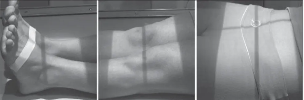
The examination is performed in two stages. In the first one, with the patient ly-ing in supine position on a Potter-Bucky table, his/her feet are placed together with their longest axes forming an angle of ap-proximately 90º with the table (Figure 1); the longitudinal, central axis of the collima-tor is aligned in a way that it passes exactly
INTRODUCTION
The most accurate way to evaluate the difference in length between lower ex-tremities is by means of imaging studies(1).
Scanography was first described by Merrill in 1942(2). In 1953, Dr. Juan Farill described
a practical technique for measuring differ-ences in length between the lower limbs(3).
The principle is very simple: in the
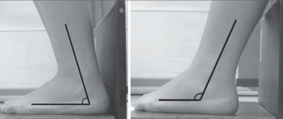
Figure 4. Positioning adopted for balancing in cases of feet deformity. Figure 2. Before the x-ray imaging is initiated, the
x-ray tube must be moved to assure that the cen-tral beam axis passes exactly between the feet and the pubic symphysis, with no need for the patient to be moved.
Figure 3. Positioning for x-ray imaging of the foot height. The result is shown on Figure 6.
between the ankles and the pubic symphy-sis of the individual (Figure 2). The patient must remain still until the examination is completed. With two lead plates, the film is divided into three segments, which are separately radiographed: in the first one, the hip x-ray is performed; in the second one, the knees; in the third one, the ankles. The numbering device at the patient’s right, indicates the side. Between images acqui-sitions, only x-ray-drawers can be moved. In no hypothesis should the chassis be re-moved from the drawer until the three ex-posures are completed.
In a second stage, the study proceeds to measure the feet height. With the feet in-ternally rotated about 30º on a wood plat-form whose posterior surface is covered with lead, the chassis is positioned imme-diately behind the feet, and an anteropos-terior x-ray view from the ankles is made. This positioning determines a dissociation of malleolus, allowing a total visualization of the tali. For an adequate imaging the foot soles must be totally resting on the platform (Figure 3). In case this is not possible be-cause of any deformity, for example, to-wards or backto-wards inclination should be tried, as necessary, until an appropriate positioning is achieved (Figure 4).
This second stage usually is neglected because of unawareness or because most of times there are no significant differences between feet height. However, there are
situations where this may happen (congeni-tal lesions, poliomyelitis sequelae, osteo-cartilaginous destruction by inflammatory or surgical processes, etc.).
Contraindications of the method
The most important aspect is the impos-sibility of a complete contact of all the faces of the lower limb with the table sur-face, because flexed positions distort bone images on x-ray films. This occurs when external fixators are utilized(5), in femur
and tibia deformities on sagittal plane or contractures with flexion of hip or knee.
Pronounced valgus, varus or equinus deformities hinder a reliable evaluation of the differences between foot heights.
SCANOMETRY (MEASUREMENTS)
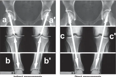
The first measurement is performed in the scanography, between the highest point on the femoral head and the projection of the center of the intercondylar notch on a line touching the femoral condyles (Figure 5a). The same procedure is performed in the contralateral limb (Figure 5a’); the dif-ference between these two measurements representing the femoral shortening.
The second measurement is the distance from the same point on the line between the femoral condyles up to the lowest point on the tibial articular surface, in the ankle (Fig-ure 5b). This meas(Fig-urement is repeated for the contralateral bone (Figure 5b’); the dif-ference between these two measurements represents the tibial shortening.
The third measurement is performed directly from the highest point on the femo-ral head up to the lowest point on the tibial articular surface (Figure 5c). This proce-dure is repeated for the contralateral limb (Figure 5c’); the difference between these two measurements was named functional shortening by Farill.
Finally, the fourth measurement con-cerns the foot height; it is performed from the lowest point of the talus, on the tibio-tarsal joint surface, up to the line resulting from the lead plate on the posterior surface of the wood platform (Figure 6d); this measurement is repeated for the contralat-eral foot (Figure 6d’). The difference be-tween these two measurements corre-sponds to the foot shortening.
Calculation and discrepancies analysis
basically be due to three types of alter-ations: The first one is bones with differ-ent lengths in relation to their contralateral; the second, is a patient with varus devia-tion or valgus asymmetry, that is, when a limb presents a greater curvature than its contralateral; the third one is isometric fe-murs and tibias and discrepant foot heights. Overlapping of such alterations is fre-quently found, so these measurements should be evaluated as whole.
Initially, the right functional measure-ment must be added to the right foot height. This calculation is repeated for the left side. Then, one measurement is subtracted from the other, so the functional discrepancy between the lower limbs is found. This is the discrepancy that must be mentioned in
Femur (cm) Tibia (cm)
Total femur + tibia (cm) (indirect measurement) Femorotibial distance (functional) (cm) Foot height (cm)
Total shortening (cm) (functional × foot height)
Right
23.4 15.2 38.6 38.6 9.2
Left
23.4 14.7 38.1 38.1 9.2
Shortening
— 0.5 < at left 0.5 < at left 0.5 < at left
— Example 1
The left lower limb is 0.5 cm < than the right lower limb (shortening due tibial discrepancies – the differences between indirect measure-ments is equal the direct measuremeasure-ments) Figure 5. Sites of measurements for calculation of femurs and tibias shortening.
Figure 6. Sites of measurements for calculation of feet shortening.
the medical report, the indirect measure-ments being utilized only for analyzing the deformity.
So, once the discrepancy between lower limbs is found, we must perform a com-parative analysis of the indirect (Figures 5a
+ 5b; Figures 5a’ + 5b’) and direct measure-ments (Figure 5c; Figure 5c’). The results will be:
– The lower limbs length discrepancy is the same both for direct and indirect mea-surements. This means that the shortening is real, i.e., femurs and/or tibias present different lengths (example 1);
– Indirect measurements indicate limb length equality, and direct measurements indicate limb length discrepancy. This in-dicates that the shortening is probably due to a varus or asymmetrical valgus deformity (example 2);
– Both the direct and indirect measure-ments indicate a discrepancy between lower limbs. In this case, there is summa-tion of these deformities (actual shortening + varus/valgus deformity)(example 3).
Although the indirect measurement is aimed only at defining whether the limbs shortening is real or is due to a varus/vgus deviation, this analysis should be al-ways performed, since it may affect directly the therapy of the patient.
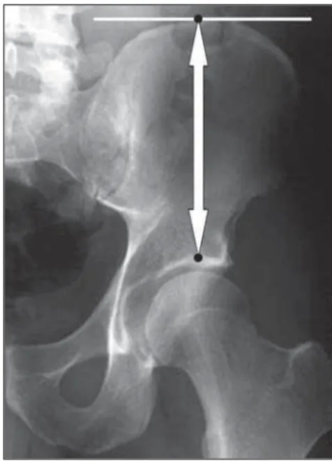
As regards the feet, the evaluation of the discrepancy between heights provides es-sential information. Some times femurs and tibias may present lengths equality and a discrepancy between foot heights; if this discrepancy is significant and we fail to perform this part of the examination, we are likely to fail in diagnosing an asymmetry in the total lower limbs length. On the other hand, a discrepancy between femurs and/ or tibias could be balanced by an opposite asymmetry in foot heights; in this case, a treatment for the functional measurements discrepancy would be contraindicated (ex-ample 4). The Farill technique does not take into consideration the highest point from the iliac crest to the acetabulum – Figure 7). However, this measurement might to be
performed with the same objective of the foot height measurement(6).
In the cases where there are knees dys-plasias, and a line cannot be drawn between femoral condyles, Farill recommends that only direct measurements are utilized in conjunction with the foot height measure-ments.
In cases of hip or ankle dysplasias, the author does not mention alternatives; for these cases, we suggest the method em-ployed by Terry et al.(7),where the
measure-ment is performed directly from the ante-rior supeante-rior iliac spine to the outermost point of the lateral malleolus. For this pur-pose a film with only two exposures is
nec-essary, with each exposure including the anatomical points of reference (anterosupe-rior iliac spine and lateral malleolus). Even so, it is our understanding that the foot height as well as the iliac wings measure-ments should be performed and included in the discrepancies calculation.
In our opinion, the Bell-Thompson method (with a millimetric ruler), although being recommended by some authors(8,9),
does not offer any substantive advantages over the Farill technique. As the ruler re-mains positioned on the chassis, it does not follow the magnification of the long bones in the radiographic imaging, which could result in measurement errors(10).
Addition-ally, for demanding a strict immobilization of the patient, it is very difficult to employ this method in children(8).
The panoramic x-ray of lower limbs is a very accurate method and presents as an advantage the possibility of being per-formed in orthostasis(10). However, it
pre-sents the inconvenience of not being widely available, besides the high cost. Also, it does not measure appropriately feet and iliac wings heights, and must be complemented by x-rays appropriate for such measurements.
The measurement of lower limbs dis-crepancy by means of CT topogram is men-tioned by some authors as the most accu-rate method for diagnosis of lower limbs asymmetry(5,11). This is true, mainly in the
cases where a complete resting of the foot soles on the platform is not achieved (de-formities, utilization of external fixators, etc.); in these cases, it is necessary to per-form a lateral topogram with the measure-ments on this view(5). Additionally, amongst
the methods analyzed in the present study, this is the method with lowest radiation dose(5,10,11), and is the method of choice for
young patients who need serial studies during the therapy management. But, be-sides not being widely available, presents high cost(10).
In summary, considering the low cost, high availability and reasonable accuracy, we recommend the Farill technique,
comple-Femur (cm) Tibia (cm)
Total femur + tibia (cm) (indirect measurement) Femorotibial distance (functional) (cm) Foot height (cm)
Total shortening (cm)
Right 23.4 15.2 38.6 38.6 9.2 Left 23.4 14.7 38.1 37.6 9.2 Shortening — 0.5 < at left 0.5 < at left 1.0 < at left
— Example 3
The left lower limb is 1.0cm < than the right lower limb (0.5cm due the tibial shortening, and 0.5cm due the varus or valgus shorten-ing)
Femur (cm)
Tibia (cm)
Total femur + tibia (cm) (indirect measurement) Femorotibial distance (functional) (cm)
Foot height (cm)
Total shortening (cm)
Right 23.4 14.7 38.1 38.6 9.2 Left 23.4 14.7 38.1 38.1 9.2 Shortening — — — 0.5 < at left
— Example 2
The left lower limb is 0.5 cm < than the right lower limb (shortening due the difference of varus or valgus deviation)
Femur (cm) Tibia (cm)
Total femur + tibia (cm) (indirect measurement) Femorotibial distance (functional) (cm) Foot height (cm)
Total shortening (cm)
Right 23.4 15.2 38.6 38.6 8.7 Left 23.4 14.7 38.1 38.1 9.2 Shortening — 0.5 < at left 0.5 < at left 0.5 < at left 0.5 < at right Example 4
There is no difference between the lower limbs, since the discrepancy between femurs + tibias is balanced by the inverted differ-ence between feet.
mented with an iliac wing measurement. In cases where there is a contraindication, we recommend a panoramic x-ray or computed tomography.
REFERENCES
1. Lampe HI, Swierstra BA, Diepstraten AF. Mea-surement of limb length inequality. Comparison of clinical methods with orthoradiography in 190 children. Acta Orthop Scand 1996;67:242– 244.
2. Merrill OE. A method for roentgen measurement of the long bones. Am J Roentgenol Radium Ther Nucl Med 1942;48:405–406.
3. Farill J. Orthoradiographic measurement of short-ening of the lower extremity; technic. Med
Ra-diogr Photogr 1953;29:32–38.
4. Dahl MT. Limb length discrepancy. Pediatr Clin North Am 1996;43:849–865.
5. Aaron A, Weinstein D, Thickman D, Eilert R. Comparison of orthoroentgenography and com-puted tomography in the measurement of limb-length discrepancy. J Bone Joint Surg Am 1992; 74:897–902.
6. Badii M, Shin S, Torreggiani WC, et al. Pelvic bone asymmetry in 323 study participants receiv-ing abdominal CT scans. Spine 2003;28:1335– 1339.
7. Terry MA, Winell JJ, Green DW, et al. Measure-ment variance in limb length discrepancy: clini-cal and radiographic assessment of interobserver and intraobserver variability. J Pediatr Orthop 2005;25:197–201.
8. Lebouchard R, Denis JP, Trope J, Duranteau Mme. Mensuration radiologique osseuse par la méthode de Bell Thompson. J Radiol Electrol Arch Electr Medicale 1956;37:108–110.
9. Delouvrier JJ, Nahum H. Longueur des membres. Précision des méthodes orthoradiographiques. J Radiol 1981;62:647–651.
10. Machen MS, Stevens PM. Should full-length standing anteroposterior radiographs replace the scanogram for measurement of limb length dis-crepancy? J Pediatr Orthop B 2005;14:30–37. 11. Aitken AG, Flodmark O, Newman DE, Kilcoyne