Resumo
Nos custos totais de exploração de matérias-primas minerais, o transporte participa com 30-60%, o número total de empregados no transporte excede 35%, enquanto o consumo total de energia para o transporte na mina é acima de 40%. Todos esses valores mostram que o transporte representa um dos processos tecnológicos mais importantes na exploração subterrânea de matérias-primas minerais e que a questão de transporte é muito importante, como na escolha do tipo de sistema de transportação, como também na sua projeção, exploração e manutenção. A efi ciência do transporte, além de muitos parâmetros técnicos e tecnológicos de exploração, como também de condições mineiro-geológicas, depende, também, da escolha de vias de transporte optimais, que, se conseguem através de conexão exata de locais subterrâneos de minas com pontos da rede mineira na superfície do terreno. A escolha de vias optimais de transporte mineiro representa uma das tarefas mais importantes nas medições mineiras. Essa obra mostra a maneira de nivelamento indireito do triângulo de conexão em fossa através de método de nivelamento indireito.
Palavras-chave: Medições mineiras, transporte, conexão, triângulo de conexão, nivelamento indireito.
Abstract
In total costs of ore mining, haulage participates with 30-60%; the total number of workers engaged in the transportation exceeds 35%, while the participation of transportation in the total power consumption amounts to over 40%. All these values indicate that transportation is one of the most signifi cant challenges in the underground mining of ore deposits and that haulage analysis is very important both in selecting the haulage type and its design, utilization and maintenance. In addition to various technical mining parameters, together with mining and geological conditions, haulage effi ciency depends on the selection of optimal haulage drives, which can be achieved by accurately connecting the underground mine workings with mine network points on the surface of a site. The selection of the best mine haulage routes is one the most critical tasks in mine surveying. This paper shows how to adjust a junction triangle on a working level using the parametric adjustment method.
Keywords: Mine surveying, underground mine haulage, junction triangle,
parametric adjustment.
Aleksandar Ganic
Associate Professor University of Belgrade, Faculty of
Mining and Geology E-mail: [email protected]
Ivica Ristovic
Associate Professor University of Belgrade, Faculty of
Mining and Geology E-mail: [email protected] E-mail: [email protected]
Dragan Djordjevic
Professor University of Belgrade, Faculty of
Mining and Geology E-mail: [email protected]
Milivoj Vulic
Associate Professor University of Ljubljana, Faculty of Natural Sciences and Engineering
E-mail: [email protected]
Mineração
Parametric adjustment of a junction triangle
in terms of the precise construction of
haulage drives in underground mines
1. Introduction
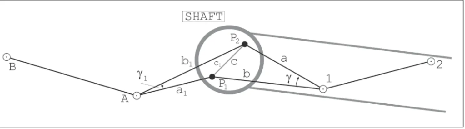
Combined haulage systems (railway transport - hoisting shaft) are the most applied systems in underground mines, both in Serbia and in the nearby countries. Connecting the underground mining workings is an important part of haulage design due to the fact that all the subsequent works follow the connection results, and therefore their accuracy depends largely on the accuracy of the connecting procedure (Ristovic, 2006). One of the most applied connection methods through a vertical shaft is the Weisbach or “junction triangle method” (Figure 1). The usual adjustment procedure for junction triangles is based on the conditional adjustment method.
The objective of the connecting procedure is to connect the stopes and the underground workings of a mine, or the related working level of a mine, with the site surface. More accurately, the connecting procedure determines the horizontal coordinates of the working level of the mine within the same reference system of the surface topography.
The connection through mine workings can be carried out regardless of its position in space, but the most diffi cult and the most complex connecting procedure is the one established through vertical workings (Vižintin et al., 2008). In such a case, two plumb lines are projected through the mine’s main shaft to represent a straight, vertical line. Therefore, the X and Y coordinates of the plumb lines in the surface will be the same as of the underground working level of the mine. By creating various geometrical fi gures and by measuring angular and length values, on the basis of known coordinates of the plumb lines, the coordinates of the fi rst point and the direction angle of the fi rst side of a future underground theodolite traverse are calculated, which is the objective of connecting.
2. Connecting by the junction
triangle method
In connecting main mine galleries through one vertical shaft, the Weisbach method is mostly used, which is also
known as the Junction triangle method. Vertical plumb lines in the shaft with the given point beside the shaft on the surface of the site, and with an unknown point on the mine level form two linked triangles having one common side - the side between the plumb lines. In these triangles, all of the three sides and the angle against the side between the plumb lines are measured, and it is a common practice that, due to a lower impact of errors of length measuring, the triangles are oblique (α <20°; β >160°) (Borshch-Komponiets et al., 1989). When dealing with oblique triangles like the latter, the unknown angles α and β are calculated by applying the Sinus theorem. Four values are measured in each triangle, i.e. one more measurement per each triangle is available, which enables the measurement results to be included in the process of strict adjustment. However, most technical journals tend to emphasize the adjustment of non-oblong junction triangles. The reason for the “non-adjustment” of oblong junction triangles is because the measurements carried out therein are more accurate, and therefore there are no signifi cant differences between the approximate and adjusted coordinates of the points on the working mine level. Hence, the adjustment process becomes more complex, and more comprehensive, requiring longer measurements which may increase the possibility of errors. However, if these were compelling arguments once, now such a concept is completely surpassed (Ganic & Djordjevic, 1999).
The adjustment of junction triangles is currently carried out via the conditional adjustment method, where, because of one redundant measurement per triangle, there is one conditional equation for each triangle, both on the site surface and on the working mine level. However, professional papers have never presented this possibility and the application of the parametric adjustment of a junction triangle on a working mine level. Parametric and conditional adjustment are based on the total least-squares method (Golub & Van Loan, 1996). For this reason, these two ways of calculation will give the same fi nal results (Blaha, 1984). Nevertheless, due to its advantages, the parametric adjustments is applied more frequently than the conditional adjustment.
3. Parametric adjustment
of a junction triangle
The parametric adjustment has been applied to a junction triangle taking into account measurements on a working mine level, as follows:
• 3 measured horizontal directions from an unknown point 1 (α
1, α2, α3). • 3 measured horizontal lengths
from point 1 towards an unknown point 2 on the working mine level (d
1) and towards plumb lines (d2, d
3). The length between the plumb lines on the working mine level is measured for the purpose of the known measurement accuracy control (|c
m- cr| ≤ 3mm), but it is not included in the adjustment process.
The given adjustment data are the coordinates of the plumb lines P
1 and P
2, calculated on the basis of the measurements on the surface of the site. It is also necessary to determine the approximate coordinates of the unknown points 1 and 2 on the working mine level.
In the parametric adjustment of working mine level measurements, there are six measured values available, and fi ve unknown values, namely: Y and X coordinates of the points 1 and 2 and the defi nite angle for the orientation of the observed horizontal directions from point 1 (Hu & Tang, 2001).
In the parametric adjustment, it is necessary to establish functional connections among measured values and unknown variables, based on which residual equations are created (Aleksic, 1990; Strang & Borre, 1997, Fan & Yao, 2005). The residual equations are then converted into standard equations, which are solved in increments, resulting in this case on the coordinates of the unknown points 1 and 2 on the working mine level.
3.1 Residual equations for
the measured horizontal
directions
The functional relation for the measured horizontal directions is as follows:
si +
si = si + zs (1)
Where:
si - Measured horizontal directions from the station S towards the points 1, 2,... i. si - Residuals of the corresponding horizontal directions.
si - Direction angles from the point S towards the points 1, 2,... i. z
s - Angle for the orientation of horizontal directions measured from the station S. If the unknown direction angles and the orientation angle are expressed through approximate values and corresponding increments such as:
si = n
si + si (2)
z s = zs
°
+ z
s (3)
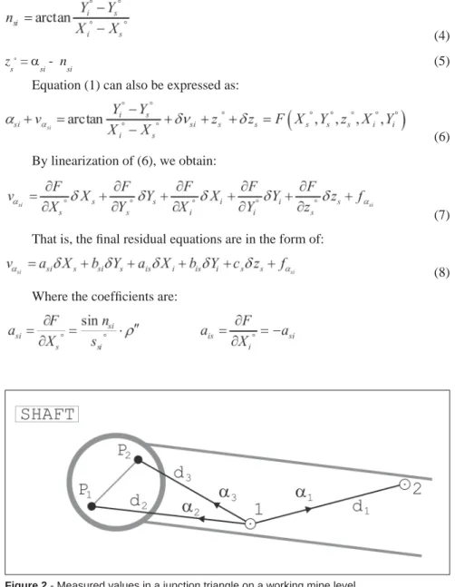
Then, the approximate values of the unknowns are calculated according to the following equations: (4) z s ° =
si - nsi (5)
Equation (1) can also be expressed as:
(6)
By linearization of (6), we obtain:
(7)
That is, the fi nal residual equations are in the form of:
(8)
Where the coeffi cients are:
And the free elements are:
The fi nal set of equations (8) refers to horizontal directions perceived between two unknown points. For directions perceived from an unknown point towards the given points, the increments are as follows:
X
i = 0; Yi = 0
So the residual equations are:
(9)
3.2 Residual equations for measured horizontal lengths
The functional relation for measured horizontal lengths is as follows:
(10)
Where: d
si - Measured horizontal lengths between the point S and points 1, 2,... i;
ν
dsi - Residuals of corresponding horizontal lengths; d
si’ - Adjusted values of horizontal lengths.
If in equation (10), the most probable length values are replaced by approximate values and their corresponding increments, this equation becomes:
(11)
Whereby the approximate lengths are calculated on the basis of approximate coordinates of the points, according to the equation:
(12)
Therefore, equation (11), becomes:
(13)
By linearization of the equation (13):
(14)
We obtain the fi nal residual equations for the measured horizontal lengths:
(15)
Where the coeffi cients are:
And the free elements are:
The same applies to fi nal residual equations for measured directions; equation (15) refers to the measured lengths between an unknown point and the given ones and the fi nal residual equations are in the following form:
(16)
3.3 Final residual equations for the parametric adjustment
of a junction triangle in a working mine level
Taking into account Figure 2 and the equations (8), (9), (15) and (16), the residual equations in the parametric adjustment of measurements in a junction triangle on a working mine level are as follows:
(17) In accordance with the fi nal set of residual equations (17), the coeffi cient matrix of error equations, the free element vector, and the weight matrix, based on standard deviations to the measured directions and lengths are created. Then, the parametric adjustment is carried out according to the known equations, whereby both the coordinates and their increments of the unknown points on the working mine level are obtained according to the equations:
(18)
This solution properly addresses the issue of the parametric adjustment of a junction triangle on the working mine level.
4. Connecting a haulage gallery in the coal mine
Soko by applying the parametric adjustment of a
junction triangle
Soko’s Brown Coal Mine has one haulage shaft and one ventilation shaft, both 160 m deep. Mine development has been carried out through a series of slopes and horizontal galleries. The haulage shaft was subsequently deepened for another 100m, taking its total depth to 260m. New drives were also constructed (1 and GTN-2) to enable access to the Eastern limb of the Central fi eld. The mining method in the Soko Mine is a variant of the room-and-pillar method, with the construction of level drives alongside the seam, with roof coal slicing in retreat. Production is carried out simultaneously through two level drives.
Figures 3, 4 and 5 show geological cross sections through the main underground workings of the Central Field Eastern Limb, in Soko’s Brown Coal Mine.
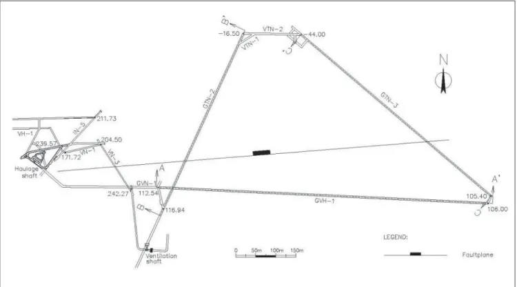
The solution of opening the Eastern Limb of the Central Field is based on the division of a mineable deposit into two levels. The first level is located at elevation -44m to provide working access to the Western and Central fi elds above such elevation. The second level is projected at elevation -150m in order to provide access to the Central fi eld between the fi rst and the second levels. The opening of the -44m level was envisaged to be carried out in two stages. The fi rst stage includes the construction of the main access from the surface to the bottom of the haulage shaft as well as ventilation, haulage and other operating conditions necessary for the continuation of works. The general layout of the working drives of such arrangement is shown in Figure 6.
The connection of the working drives shown in Figure 6 has been carried out using the junction triangle method. Two plumb-bobs, with horizontal coordinates defi ned by the intersections, were suspended from the surface down to one of the haulage drives. The following measurements were taken within the haulage drive:
• Three sets of angular measurements by theodolite Wild T2.
• Te n r e p e t i t i o n s o f l e n g t h measurements by a precise steel band.
The proposed procedure for the parametric adjustment of the junction triangle is:
• Coordinates of the plumb lines P 1 and P
2 obtained on the basis of the measurements on the surface:
Y
P1=660.3738m XP1=812.7780m Y
Figure 3 - Geological cross section longitudinal to drive GVH-1.
Figure 5 - Geological cross section longitudinal to drive GTN-3.
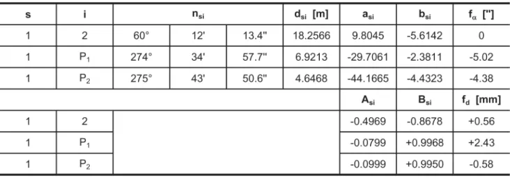
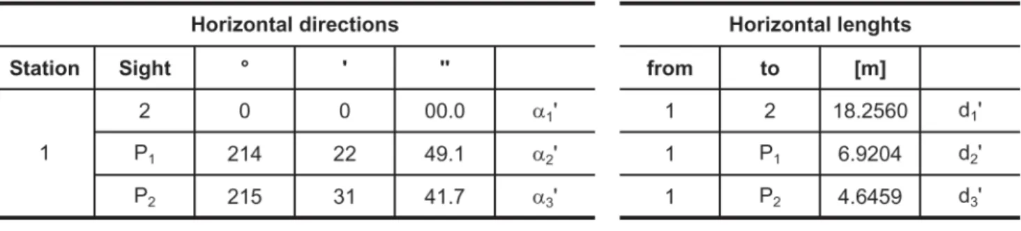
Table 1 - Results of measurements of horizontal directions and lengths.
Table 2 - Coeffi cients and free elements of the fi nal residual equations.
• Approximate coordinates of the points 1 and 2 in the haulage drive:
Y 1
°=667.2730m X 1
°=812.2250m
Y 2
°=683.1160m X
2
°=821.2970m
• Results of measurements of horizontal directions and lengths in the haulage drive (Table 1).
• Standard deviations to the measured values:
σ
α = 5” σd = 0.5mm
Based on the parametric adjustment procedure, coeffi cients and free elements of the fi nal residual equations are calculated according to equations (8) and (15) (Table 2).
Therefore according to the set of equations (17), the coeffi cient matrix of the residual equations will be:
Free element vector: f T = [0 -5.02 -4.38 +0.56 +2.43 -0.58]
As well as the weight matrix: P
By applying the corresponding matrix operations, an inverse coeffi cient matrix of standard equations is obtained:
Where: N = AT . P. A
As well as the free element vector:
nT = (AT
. P. f)T
= [+301.2832 +167.7458 -9.4006 +27.6232 +48.2401]
Based on the coeffi cient matrix and free element vector, the increment vector is obtained:
xT = - (N-1 . n)T = [+0.146mm -0.915mm +6.976” +0.406mm -1.705mm]
The most probable values of the coordinates of unknown points in the haulage drive obtained by the parametric adjustment will be:
Y
1 = 667.2730m - 0.9mm = 667.2721m X1 = 812.2250m + 0.1mm = 812.2251m Y
2 = 683.1160m - 1.7mm = 683.1143m X2 = 821.2970m + 0.4mm = 821.2974m The transposed residual vector for the measurement results will be:
νT
= [ 0 -0,21” +0,21” 0 +1,50mm -1,50mm]
And the most probable values of the measured values in the haulage drive will be in Table 3.
The standard deviations to the coordinates of the unknown points in the haulage drive are:
σ
y1 = 1.50mm σx1=2.06mm
σ
y2 = 4.17mm σx2=8.25mm
For the purposes of control, a conditional adjustment of the junction triangle was also carried out, with the same parameters ( ) and the following adjusted values:
• Angle between plumb lines = 1°08’52.3” (the difference between the value obtained by the parametric adjustment and the conditional one is = |0.3”| ).
• Side distance between the plumb line P
1 and the point 1 in the haulage drive d
2=6.9199m ( = |0.5mm|). • Side distance between the plumb
line P
2 and the point 1 in the haulage drive d
3=4.6464m ( = |0.4mm|). The coordinates of points 1 and 2 in the haulage drive are calculated in the draft of traverse, on the basis of conditionally adjusted measurements as follows:
Y
1 = 667.2716m X
1=812.2250m Y
2 = 683.1140m X
2=821.2969m
And, as it was expected, these coordinates differ only slightly from the coordinates obtained by the parametric adjustment.
5. Conclusion
The parametric adjustment is a strict adjustment method based on the least-squares method. As such, the parametric adjustment, if well performed, will give the same results as any other adjustment based on the least-square method. In comparison with other strict adjustment methods, the parametric adjustment has several advantages of which the most important are: direct calculation of unknown coordinates and an indirect assessment of the accuracy of the measurements performed and the coordinate calculations.
There are a number of commercial geodetic softwares in the market which
are also applied in underground mines in performing different tasks. The fact is that all softwares will give the same fi nal results, if they are based on adjustment according to the least-squares method. However, end users are not familiar with the algorithm according to which the software is realized, that is, the unknown is the applied adjustment method according to which calculations are made.
The procedure shown in the paper enables a simple, but effi cient verification method for commercial softwares and their determining method, if the calculations were made according to the least-squares method and if the obtained results are the most probable values of unknown variables. The verifi cation of the procedure was made by comparing results obtained by the conditional adjustment method, on the example of the haulage drive connection in the coal mine Soko.
Thus the experts can, in practice, organize a measurement program in a
simpler and better way; that is, they can achieve better results and a more effi cient work, and thereby ensure lower operating costs for the company.
6. Bibliographic references
ALEKSIC, I. Geodezija 3 (Geodesy 3). Belgrade: Naucna knjiga, 1990. 245p. BLAHA, G. Tensor structure applied to the least -squares method, revisited. Journal
of Geodesy, v.58, n.1, p.1-30, 1984
BORSHCH-KOMPONIETS, V. et alli. Mine Surveying. Moscow: Mir Publishers, 1989. 365p.
FAN, J. AND YAO, Q. Nonlinear time series: nonparametric and parametric
methods. Springer Netherlands, p.551, 2005.
GANIC, A. AND DJORDJEVIC, D. Izravnanje prikljucnih trouglova izduzenog
oblika (Adjustment of Connected Triangles Elongated in Shape). Underground
Mining Engineering, v.8, n.10, p.95-98, 1999.
GOLUB, G. AND VAN LOAN, C. Matrix Computations. Baltimor and London: The Johns Hopkins University Press, 1996. 694p.
HU, W.C. AND TANG, W.H. Automated least-squares adjustment of triangulation-trilateration fi gures. Journal of Surveying Engineering, v.127, i.4, p.133-142, 2001. RISTOVIC I. Optimization of parameters of continuous haulage systems for
underground mining of metallic and non-metallic mineral raw materials.
Belgrade: Faculty of Mining and Geology, 2006. 190p. (Doctors Thesis). STRANG, G. AND BORRE, K. Linear Algebra, Geodesy and GPS. Wellesley:
Wellesley College, 1997. 624p.
VIŽINTIN, G. et alli. Development of environmental criteria for estimation of land development using GIS. RMZ - Materials and Geo-environment, v.55, n.2, p.237-258, 2008.
Artigo recebido em 08/06/2009 e aprovado em 19/11/2009.