ISSN 1517-7076 artigo e11800, 2017
Corresponding Author: Maria do Carmo Rangel Received on: 11/12/2015 Accepted on: 05/12/2016
10.1590/S1517-707620170001.0132
Effect of La
0.8Sr
0.2MnO
3powder addition in the
precursor solution on the properties of cathode
films deposited by spray pyrolysis
Caio Luis Santos Silva 1, Leonardo Marques Gama 2, Jacqueline Amanda Figueiredo dos Santos 3, Herval Ramos Paes Jr. 2, Rosana Zacarias Domingues 3, Maria do Carmo Rangel 1
1
Grupo de Estudo em Cinética e Catálise/UFBA, Rua Barão de Geremoabo, s/n, Ondina, Salvador-BA, Brazil e-mail: [email protected]; [email protected]
2
Laboratório de Materiais Avançados/UENF, Av. Alberto Lamego, 2000 - Horto, Campos dos Goytacazes-RJ, Brazil
e-mail: [email protected]; [email protected]
3 Laboratório de Materiais e Pilhas a Combustível/UFMG, Av. Ant. Carlos, 6627, Pampulha, Belo Horizonte-MG, Brazil
e-mail: [email protected]; [email protected]
ABSTRACT
Films of lanthanum strontium manganite, LSM (La0.8Sr0.2MnO3) were deposited on yttria stabilized zirconia (YSZ) substrates by different methods aiming to establish the most suitable route to prepare cathodes for solid oxide fuel cells (SOFC). Samples were obtained by using a solution of lanthanum, strontium and manganese nitrates or a dispersion of the LSM powder in this solution. Both commercial and synthetized LSM powders were used, the last one obtained by amorphous citrate method. The films were deposited by spray pyrolysis on YSZ substrates prepared by uniaxial and isostatic pressing. Samples were characterized by scanning electron microscopy, confocal laser scanning microscopy, X-ray diffraction and two-probe conductivity measurements. The area specific resistance and relaxation to cathodic activation were measured by electrochemical impedance spectroscopy. The substrate obtained by uniaxial pressing and the commercial LSM produced films with the highest amount of surface cracks. The film obtained from the suspension showed area specific resistance and activation energy lower than the other produced from the solution. For both samples, the cathodic activation process resulted in an initial reduction of the total resistance of around 20%, the sample produced from the suspension being more resistant to relaxation. Therefore, the LSM suspension is more suitable than the salts solution for preparing films by spray pyrolysis on YSZ substrates to obtain efficient cathodes for SOFC.
Keywords: lanthanum strontium manganite, cathode, spray-pyrolysis, fuel cell, SOFC.
1. INTRODUCTION
Currently, great attention has been devoted to global warming, mainly caused by the greenhouse gases emission from burning of fossil fuels, the current primary source for power generation [1-3]. Because of the need for more efficient energy conversion technologies, fuel cells emerge as one of the most promising alternatives [4]. These devices may be used in small or large applications as well in mobile or stationary operations [5]. Among the various types of fuel cells, the Solid Oxide Fuel Cell (SOFC) is one of the most advantageous and versatile option, due to several reasons. One of the most important feature is that all its components are solid, allowing the use of films in manufacturing processes. In addition, they use non-precious metal catalysts, have high theoretical efficiency conversion values and allow electrical and heat cogeneration. Moreover, because of their high operation temperatures (800 to 1000 °C), a wide variety of fuels can power the SOFCs [6-8]. Despite these advantages, these devices still have some obstacles to commercial applications. The main one is the high cost of solid components, which could be decreased if the SOFCs operate at lower temperatures, such from 500 to 800 °C [9, 10]. However, the temperature reduction causes a decrease in cell performance. A promising alternative to overcome this difficulty is by using films, which reduce the layer thickness, providing a decrease in ohmic losses and optimizing the interface between the electrodes, where the electronic and ionic exchanges occurs [11].
the cell. In addition, the cathode must have porous microstructure and chemical stability during operation as well as high electrical conductivity [12]. Besides these properties, this component must have high catalytic activity for the reduction of oxygen. Several doped and mixed oxides have been proposed as cathode but lanthanum strontium manganite (LSM) has been considered the most promising material for high temperature applications. This is due to its high electronic conductivity, chemical stability, thermal compatibility with the electrolyte (yttrium stabilized zirconia, YSZ) and high catalytic activity for oxygen reduction [7, 13].
Various methods have been used for manufacturing LSM cathodes, including sputtering [14], organometallic vapor deposition [15], spray pyrolysis [16], flame assisted vapor deposition [17] and electrostatic spray [18]. The spray pyrolysis technique is a convenient alternative to the traditional methods, because of the simplicity, low cost, versatility, efficiency and low waste production [16]. This technique was used by CHARPENTIER et al. [11, 19], in the preparation of LSM films by a modified spray pyrolysis method. Instead of producing lanthanum strontium manganite from the precursor solutions directly onto a substrate, the La0.7Sr0.3MnO3-δ powder was previously prepared and then added to the solution containing lanthanum nitrate, strontium acetate and manganese nitrate. It was achieved 0.7 V, 100 mA.cm-2 at 850 °C in a SOFC powered by hydrogen produced by external reforming from methane and steam. Because these results are promising, it is interesting to compare them with the values obtained using only the solution of reagents salts in the preparation of cathodes, under the same conditions.
With this goal in mind, the effect of adding lanthanum strontium manganite powder to the precursor solution of films deposited by spray pyrolysis was studied in this work. The influence of LSM solid precursor (commercial and synthetized) and of the kind of YSZ substrate was also investigated. It is expected to obtain LSM films with suitable properties for cathodes in solid oxide fuel cells at intermediate temperatures (SOFC-IT), with superior performance as compared to films deposited by spray pyrolysis from solutions containing only the precursor salts.
2. MATERIALS AND METHODS
2.1 Sample Preparation
In order to study the effect of the kind of substrate, yttria stabilized zirconia substrates were obtained using two different pressing procedures. For the first one, the substrate (YSZ-U) was produced by uniaxial pressing at 100 MPa, using 3 g of YSZ powder. After pressing, the substrate was heated (3 °C min-1) up to 1000 °C, kept at this temperature for 4 h, heated (2 °C min-1) up to 1250 °C and kept at this temperature for 4 h. They were then rinsed with deionized water in an ultrasonic bath. Substrates with diameters and average thickness of 25 and 1 mm, respectively, were produced. The second type of substrate (YSZ-I) was obtained by uniaxial pressing of YSZ (2 g per tablet) under 26 MPa and subsequently under isostatic pressing at 200 MPa. The substrate was heated (5 °C.min-1) up to 1250 °C, kept at this temperature for 4 h, then to 1500 °C (4.8 °C.min-1) and kept at this temperature, for 5 h. It was then lightly sanded (220 sandpaper) and dipped in an aqueous solution of 10% hydrofluoric acid. The system was heated to 65 °C, for 10 min. The pellets were washed with distilled water and dried in an ultrasonic bath at 60 °C. Substrates with average dimension of 16 mm in diameter and 1.5 mm thickness were produced.
For the preparation of LSM films, the spray pyrolysis deposition [16] was used, the parameters of deposition and thermal treatment being described in Table 1. Three kinds of precursor solutions were used for the production of La0.8Sr0.2MnO3 films: (i) solution of precursor salts (lanthanum, strontium and manganese nitrates); (ii) suspension obtained by the addition of LSM powder (prepared by the amorphous citrate method) to the solution of precursor salts and (iii) suspension obtained by adding commercial LSM powder to the solution. A LSM containing 20% Sr doping on the La-site was used. This formulation was chosen because this solid has shown considerable oxide ion conductivity and sufficient electronic conductivity [5].
Table 1: Deposition and thermal treatment parameters of the LSM films deposited by spray pyrolysis technique.
PARAMETER VALUE
Distance nozzle-susbtrate 30 cm
Deposition time 30 min
Deposition temperature 400 °C
Thermal pre-treatment 500 °C for 30 min Thermal treatment 900 °C for 2 h
In a first preparation, the LSM films were obtained using only the solution of the precursor salts. In this case, an aqueous solution (0.025 mol L-1) containing the following salts was used: lanthanum(III) nitrate hexahydrate (La(NO3)3·6H2O), strontium chloride hexahydrate (SrCl2.6H2O) and manganese (II) sulfate monohydrate (MnSO4·H2O) in a molar ratio of 8:2:10.
In the other preparations, the films were produced from the addition of LSM powder to the aqueous solution of the precursors. Both commercial (Sigma Aldrich) and synthesized LSM powders were used. The films were prepared using a suspension of 0.72 g of La0.8Sr0.2MnO3 powder in 250 mL of a solution of salts (0.0125 mol.L-1). In preparing the LSM powder, the thermal decomposition of the amorphous citrate precursor method was used [20]. A stock solution (10 M) of lanthanum (La(NO3)3·6H2O), strontium (Sr(NO3)2) and manganese (Mn(NO3)2·4H2O) nitrates was prepared, using a molar ratio of 8:2:10. A citric acid solution with the equivalents grams of citric acid and total equivalents grams of metals ratio equal to unity (EgAcid/EgLa:Sr:Mn = 1) was also prepared. The solutions were mixed in a glass reactor at room temperature and heated to 70 °C at a residual pressure of 10 Torr until complete solvent removal. The solid obtained was dried at 70 °C for 96 h, giving rise to the amorphous precursor. Subsequently, it was ground, sieved (100 mesh) and heated (2 ° C.min-1) under air flow up to 1000 °C, being kept at this temperature for 2 h.
2.2 Sample Characterization
The substrates and films were gold-sputter coated and characterized by scanning electron microscopy using a Shimadzu Superscan SS-550 under different magnifications. The samples were also characterized by confocal laser scanning microscopy using an Olympus LEXT OLS4000, operating with a 408 nm wavelength laser diode. A 3D image of the surface was obtained by moving the sample along the Z axis and the reconstructed image representing the surface profile was achieved through surface analysis software, from which it was possible to estimate the thickness of the films from the micrographs of the cross section.
The X-ray diffraction patterns in the Bragg–Brentano geometry were obtained with a Shimadzu XRD-7000 diffractometer, using CuK radiation (1.5405 Å) at 40 kV and 30 mA, using a scanning speed of 2 deg/min, 2θ between 20 and 80°. This technique allows to identify the crystal structure and the phases present in the synthesized samples, as well as to estimate the average crystallite size using the Scherrer Equation [21], where Dhkl is the average crystallite size, k is the shape factor (considered as 0.9), is the wavelength of incident X-ray, β is the full width at half maximum (FWHM) of (020) peak and θ is the Bragg angle of diffraction peak.
) cos( . . hkl hkl k Dhkl (1)
The electrical conductivity measurements were performed by the two-probe method. In this experiment, the sample was placed on a heating plate and two copper wires were connected to the sample using platinum paint. The wires were connected to an Agilent 3458A multimeter operating on the resistance measurement function. The electrical conductivity values were obtained in the temperature range from 200 to 575 °C, in order to obtain a preliminary evaluation of the contact between the electrode and the electrolyte.
2.3 Evaluation of Samples Electrochemical Performance
3. RESULTS AND DISCUSSION
3.1 Morphological, structural and electrical characterization of substrates and films
Figure 1 shows the micrographs of YSZ substrates obtained by confocal laser microscopy. It can be seen that both surfaces showed no cracks and YSZ-I substrate showed a surface with higher roughness average (0.650 m) than the YSZ-U substrate (0.234 m). This result may be related to the stages of sanding and treatment with hydrofluoric acid carried out on the YSZ-I substrate [22].
(a) (b)
Figure 1: 3D micrographs (180 x) obtained by confocal microscopy of (a) YSZ-U and (b) YSZ-I substrates. The Ox and Oy scales are the same and each division is equal to 640 m. In the Oz each division is equal to 328.5 m.
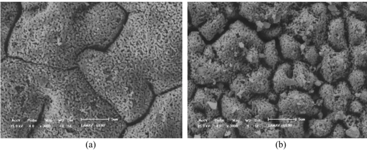
Figure 2 shows the scanning electron micrographs of the films obtained from the solutions of the reactants (YSZ-U/LSM) and those produced by the addition of synthesized LSM powder to the precursors solution (U/LSM-CI). As we can see, the U/LSM-CI film showed less fine grains than the YSZ-U/LSM film, indicating that the addition of the solid to the precursor solution increased the mechanical strength of the films. There is a greater coarsening of the grains in the sample (a) (YSZ-U / LSM) as compared to the sample (b) (YSZ-U / LSM-CI) generating domains of 12 and 4 , respectively. This fact is possibly related to the higher interfacial resistance due to a reduction in the number of contact points as a result of LSM powder micrometer granules in the films preparation, in agreement with other studies [11].
(a) (b)
Figure 2: Top micrographs obtained by SEM of the (a) YSZ-U/LSM and (b) YSZ-U/LSM-CI films.
The YSZ-I/LSM-CO sample (obtained by adding the commercial powder to the precursors solution) showed fewer cracks and shorter propagation length as compared to I/LSM film. On the other hand, YSZ-U/LSM-CO sample showed a greater amount of surface cracks than the YSZ-I/LSM film.
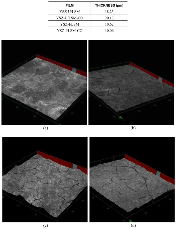
Table 2 shows the thicknesses values of the films, as roughness average (Ra), calculated on base of the arithmetic average deviation from the mean line using the LEXT® software, from the analysis of the cross section. It can be noted that there was no significant difference in the film thickness with the addition of LSM solid to the precursor solution. This result is related to the use of similar deposition parameters utilized to obtain these films (Table 1). We can also observe that the finest films were those obtained on more rough substrates, which can be explained by the penetration of the suspension in the roughness of the substrate.
Table 2: Estimated film thickness with and without addition of commercial LSM powder.
FILM THICKNESS (µm)
YSZ-U/LSM 18.23
YSZ-U/LSM-CO 20.13
YSZ-I/LSM 10.62
YSZ-I/LSM-CO 10.06
(a) (b)
(c) (d)
YSZ-I/LSM and (d) YSZ-I/LSM-CO films. The scales of Ox and Oy are the same and each division is equal to 160 m. For Oz each division is equal to 14.5 m.
The X-ray diffractograms (Figure 4) show the formation of lanthanum strontium manganite perovskite phase, identified by indexing the plans using the La0.8Sr0.2MnO3 standard (PDF 40-1100) as reference. For both cases, peaks related to the cubic phase of yttrium stabilized zirconia substrate were found (PDF 82-1246). This result is related to the penetration depth of the beam. In addition, two diffraction peaks related to segregated phases were observed. The first one, at 2θ = 27.7º, can be assigned to La2O3 phase [23] while the other, at 2θ = 66.9º, indicates SrZrO3 phase produced from the reaction of YSZ substrate with ions in the precursor solution [24]. The film deposited by using the LSM powder in the precursor solution presented a diffractogram with peaks more intense and narrower, thus indicating an increase of crystalline domains in the material.
Figure 4: X-ray diffractogram of the (a) YSZ-U/LSM and (b) YSZ-U/LSM-CO films. Phases: (*) LSM (PDF 40-1100); (o) YSZ (PDF 82-1246); (∆) La2O3 (PDF ) and (•) SrZrO3 (PDF 44-0161).
Table 3 shows the average crystallite size calculated from Equation 1. The values are in agreement with those in literature related to LaMnO3 films deposited by spray pyrolysis and doped with divalent cations [19, 25], where these crystallite sizes varied from 30 to 60 nm depending on the dopant concentration and on the annealing temperature.
Table 3: Average crystallite size of the YSZ-U/LSM and YSZ-U/LSM-CO films.
FILM AVERAGE CRYSTALLITE SIZE
(nm)
YSZ-U/LSM 34
YSZ-U/LSM-CO 56
Table 4 shows the activation energy related to the contact resistance between the electrode and the substrate obtained by the two-probe method. It can be seen that the values were similar and in accordance with those reported by GHARBAGE et al. [14], in the range between 0.081 and 0.150 eV, related to films obtained by spray-pyrolysis deposition on YSZ substrates.
Table 4: Activation energy values calculated by the two-probe method for the thin films produced with and without the commercial LSM powder.
FILM ACTIVATION ENERGY (eV)
YSZ-U/LSM 0.144
YSZ-I/LSM 0.126
YSZ-U/LSM-CO 0.138
YSZ-I/LSM-CO 0.128
20 30 40 50 60 70 80
In
te
n
si
ty
(
a
.u
.)
2 (degree)
(a)
(b) *
*
* *
o o o
3.2 Electrochemical impedance spectroscopy measurements
For the evaluation of the obtained cathodes, the simulation of impedance diagrams of the LSM/YSZ-I/LSM and LSM-CI/YSZ-I/LSM-CI cells was taken, from the equivalent circuit shown in Figure 5. In this diagram, R1 is the resistance in the electrolyte, CPE1 and R2 represent the capacitance and resistance, respectively, of the electrode (LSM Film) and W1S is the finite element of Warburg, who describes the resistance related to diffusion processes at the cathode.
Figure 5: Equivalent circuit used for evaluation of LSM/YSZ-I/LSM and LSM-CI/YSZ-I/LSM-CI cells by electrochemi-cal impedance spectroscopy.
Figure 6 shows the impedance spectroscopy diagrams obtained for the symmetric cells LSM/YSZ-I/LSM and LSM-CI/YSZ-LSM/YSZ-I/LSM-CI, in the range of 600 to 850 °C. According to GAUDON et al. [26], the electrode polarization resistance can be determined from the difference between the intersections of curves with the abscissa axis at high and low frequencies. For all curves, a significant reduction of the polarization resistance (around 50%) was observed in the studied temperature range, for the LSM-CI/YSZ-I/LSM-CI cathode, as compared to the LSM/YSZ-I/LSM cell. This result is also in agreement with the morphological characterization of the films, since the YSZ-I/LSM-CI film showed a surface with higher porosity and reduced grain size, which causes a volume increase of the boundary of triple phase region and thereby facilitates the access of the oxidizing gas, increasing the efficiency of cathodic reduction reaction [27].
(a) (b)
Figure 6: Impedance Nyquist diagram of the cells (a) LSM/YSZ-I/LSM and (b) LSM-CI/YSZ-I/LSM-CI.
Figure 7: Temperature-dependence of area specific resistance (ASR) of the cells ( ) LSM/YSZ-I/LSM and ( ) LSM-CI/YSZ-I/LSM-CI.
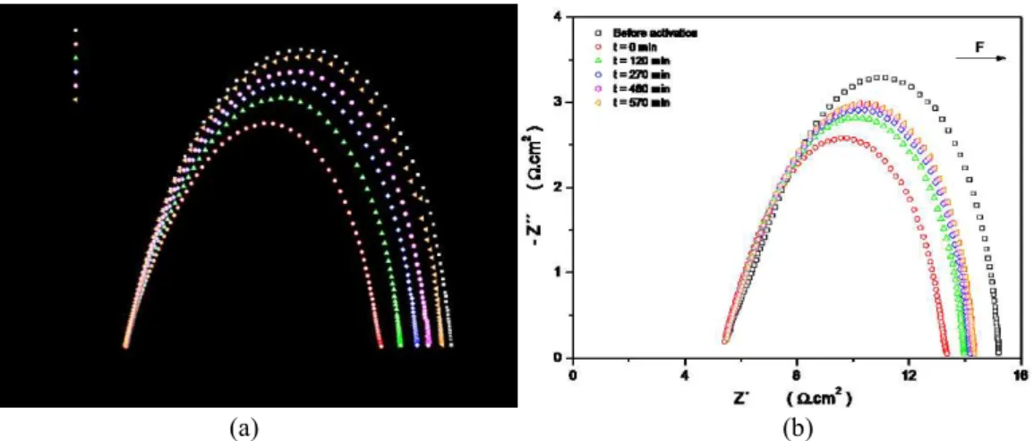
The effect of cathodic activation on the performance of films is illustrated in Figure 8. As can be seen, for both samples, the activation process caused an initial reduction in the total resistance of approximately 20%. One reason for this phenomenon is related to the contraction of the interstitial lattice parameter of man-ganese and the concomitant generation of oxygen vacancies on the surface of LSM electrode. The oxygen vacancies promote the active sites on LSM surface by favoring the dissociative adsorption and the oxygen diffusion on electrode surface [28-30].
In quantifying resistance to relaxation effect caused by cathodic polarization, the values of half-life time of activation were estimated. It was found that the sample produced from the suspension (LSM-CI/YSZ-I/LSM-Cl) showed a half-life time of activation close to 270 min, while that obtained from the salts solution (LSM/YSZ-I/LSM) showed around 180 min. It can be thus concluded that the system produced from the suspension with the powder of salts was more resistant to relaxation, showing a half-life about 1.5 times the value of the other sample.
(a) (b)
Figure 8: Impedance diagram in the Nyquist plane for the (a) LSM/YSZ-I/LSM and (b) LSM-CI/YSZ-I/LSM-CI cells as a function of time from cathodic activation.
4. CONCLUSIONS
depos-ited with the LSM powder led to a decrease of the effects caused by cathodic resistive polarization. The symmetric LSM-CI/YSZ-I/LSM-CI cell showed the lowest values of area specific resistance and activation energy, as well as greater resistance to relaxation of cathodic activation process, as compared to LSM/YSZ-I/LSM cells. Therefore, the addition of the lanthanum manganite powder doped with strontium to the precur-sor solution deposited films by spray-pyrolysis is the most suitable method for preparing La0.8Sr0.2MnO3 films to be used as cathodes for solid oxide fuel cells (SOFC).
5. ACKNOWLEDGMENTS
The authors thank the Ministério de Ciência e Tecnologia e Inovação (MCTI) for the financial support through the Brazilian SOFC Network “Rede PaCOS”. The authors also thank the support from CAPES, CNPq and FINEP.
6. BIBLIOGRAPHY
[1] AZHAR KHAN, M., ZAHIR KHAN, M., ZAMAN, K., et al., “Global estimates of energy consumption
and greenhouse gas emissions”, Renewable and Sustainable Energy Reviews, v. 29, pp. 336–344, Jan. 2014.
[2] RANGEL, M. C., CARVALHO, M. F. A., “Impacto dos catalisadores automotivos no controle da qualidade do ar”, Química Nova, v. 26, n. 2, pp. 265–277, Mar. 2003.
[3] ANG, B. W., SU, B., “Carbon emission intensity in electricity productionμ A global analysis”, S Energy
Policy, v. 94, pp. 56–63, Apr. 2016.
[4] ELLIS, M. W., VON SPAKOVSKY, M. R., NELSON, D. J., “Fuel cell systemsμ efficient, flexible energy conversion for the 21st century”, Proceedings of the IEEE, v. 89, n. 12, pp. 1808–1818, 2001.
[5] O'HAYRE, R., CHA, S., COLELLA, W., et al., Fuel cell fundamentals, John Wiley & Sons, 2016. [6] WEBER, A., IVERS-TIFFÉE, E., “Materials and concepts for solid oxide fuel cells (SOFCs) in stationary and mobile applications”, Journal of Power Sources, v. 127, n. 1–2, pp. 273–283, Mar. 2004.
[7] AMADO, R. S., MALTA, L. F. B., GARRIDO, F. M. S., et al., “Pilhas a combustível de óxido sólidoμ
materiais, componentes e configurações”, Química Nova, v. 30, n. 1, pp. 189–197, Feb. 2007.
[8] CORDEIRO, R. C., TRINDADE, G. S., MAGALHÃES, R. N. S. H., et al., “Nanostructured Ceramic
Suspensions for Electrodes and the Brazilian SOFC Network ‘REDE PaCOS,’” In: Bansal, N. P., Wereszczak, A., Lara-Curzio, E. (eds), Advances in Solid Oxide Fuel Cells II: Ceramic Engineering and Science Proceedings, v. 27, n. 5, pp. 138–152, chapter 14, Wiley Online Library, 2007.
[9] FLORIO, D. Z., VARELA, J. A., FONSECA, F. C., et al., “Direcionamentos da tecnologia industrial de
células a combustível de óxidos sólidos”, Química Nova, v. 30, n. 5, pp. 1339–1346, Oct. 2007.
[10] ANDRADE, M. L., ALMEIDA, L., RANGEL, M. C., et al., “Ni-Catalysts Supported on Gd-Doped Ceria for Solid Oxide Fuel Cells in Methane Steam Reforming”, Chemical Engineering & Technology, v. 37, n. 2, pp. 343–348, Feb. 2014.
[11] CHARPENTIER, P. “Preparation of thin film SOFCs working at reduced temperature”, Solid State
Ionics, v. 135, n. 1–4, pp. 373–380, Nov. 2000.
[12] IVERS-TIFFÉE, E., WEBER, A., HERBSTRITT, D., “Materials and technologies for SOFC-components”, Journal of the European Ceramic Society, v. 21, n. 10–11, pp. 1805–1811, Jan. 2001.
[13] SIQUEIRA, G. O., BELARDI, R. M., ALMEIDA, P. H., et al., “Determination of the Mn3+/Mn4+ ratio
in La1−xSrxMnO3±d powders”, Journal of Alloys and Compounds, v. 521, pp. 50–54, Apr. 2012.
[14] GHARBAGE, B., MANDIER, F., LAURET, H., et al., “Electrical properties of La0.5Sr0.5MnO3 thin
films”, Solid State Ionics, v. 82, n. 1–2, pp. 85–94, Nov. 1995.
[15] ORLANDO, M. T. D., CUNHA, A. G., FREITAS, J. C. C., et al., “Structure and magnetotransport
properties in plasma-sprayed La0.78Sr0.22MnO3 thick film”, Journal of Magnetism and Magnetic
Materials, v. 246, n. 1–2, pp. 10–15, Apr. 2002.
[16] RABELO, S. S., VENÂNCIO, S. A., PAES JR, H. R., et al., “Influência do Substrato nas Propriedades
Estruturais e Morfológicas de Filmes de Manganita de Lantânio Dopados com Estrôncio Depositados por Spray-Pirólise”, Matéria, v. 12, n. 1, pp. 44–53, 2007.
[18] PRINCIVALLE, A., DJURADO, E., “Nanostructured LSM/YSZ composite cathodes for IT-SOFC: A comprehensive microstructural study by electrostatic spray deposition”, Solid State Ionics, v. 179, n. 33–34, pp. 1921–1928, Oct. 2008.
[19] CHARPENTIER, P., FRAGNAUD, P., SCHLEICH, D. M., et al., “Preparation of Cathodes for Thin
Film SOFCs”, Ionics, v. 3, pp. 155–160, 1997.
[20] MOURA, J. S., SILVA, L. A., RANGEL, M. C., et al., “Síntese e caracterização de perovskitas do tipo
LaNi1-xCuxO3 para a purificação de hidrogênio para PaCOS”, Matéria, v. 15, n. 3, pp. 472–479, 2010.
[21] SCHERRER, P., “Estimation of the size and internal structure of colloidal particles by means of röntgen”, Nachr. Ges. Wiss. Göttingen, v. 2, pp. 96-100, 1918.
[22] TAMM, K., KÜNGAS, R., GORTE, R. J., et al., “Solid oxide fuel cell anodes prepared by infiltration of strontium doped lanthanum vanadate into doped ceria electrolyte”, Electrochimica Acta, v. 106, pp. 398–405, Sep. 2013.
[23] GAUDON, M., LABERTY-ROBERT, C., ANSART, F., et al., “Preparation and characterization of
La1–xSrxMnO3+δ (0≤x≤0.6) powder by sol–gel processing”, Solid State Sciences, v. 4, n. 1, pp. 125–133,
Jan. 2002.
[24] CHEN, M., LIU, Y. L., HAGEN, A., et al., “LSM-YSZ reactions in different atmospheres”, Fuel Cells, v. 9, n. 6, pp. 833–840, Dec. 2009.
[25] TODOROVSKA, R., PETROVA, N., TODOROVSKY, D., GROUDEVA-ZOTOVA, S., “Spray -pyrolysis deposition of LaMnO3 and La1−xCaxMnO3 thin films”, Applied Surface Science, v. 252, n. 10, pp. 3441–3448, Mar. 2006.
[26] GAUDON, M., LABERTY-ROBERT, C., ANSART, F., et al., “Evaluation of a sol–gel process for the synthesis of La1−xSrxMnO3+δ cathodic multilayers for solid oxide fuel cells”, Journal of Power Sources, v. 133, n. 2, pp. 214–222, Jun. 2004.
[27] JANARDHANAN, V. M., HEUVELINE, V., DEUTSCHMANN, O., “Three-phase boundary length in solid-oxide fuel cellsμ A mathematical model”, Journal of Power Sources, v. 178, n. 1, pp. 368–372, Mar.
2008.
[28] JIANG, S. P., “Development of lanthanum strontium manganite perovskite cathode materials of solid oxide fuel cells: a review”, Journal of Materials Science, v. 43, n. 21, pp. 6799–6833, Nov. 2008.
[29] BELARDI, R.-M., DESEURE, J., BRANT, M. C., et al., “Electrical study of cathodic activation and
relaxation of La0,80Sr0,20MnO3”, Ionics, v. 15, n. 2, pp. 227–232, Apr. 2009.