Inluence of reinforcement’s corrosion into hyperstatic
reinforced concrete beams: a probabilistic failure
scenarios analysis
Inluência da corrosão de armaduras em vigas
hiperestáticas em concreto armado: uma análise
probabilística dos cenários de falha
a Universidade de São Paulo, Departamento de Engenharia de Estruturas, Escola de Engenharia de São Carlos, São Carlos-SP, Brasil; b Universidade Estadual Paulista, Departamento de Engenharia Civil e Ambiental, Faculdade de Engenharia, Bauru-SP, Brasil.
Abstract
Resumo
This work aims to study the mechanical efects of reinforcement’s corrosion in hyperstatic reinforced concrete beams. The focus is the probabilistic determination of individual failure scenarios change as well as global failure change along time. The limit state functions assumed describe analyti-cally bending and shear resistance of reinforced concrete rectangular cross sections as a function of steel and concrete resistance and section dimensions. It was incorporated empirical laws that penalize the steel yield stress and the reinforcement’s area along time in addition to Fick’s law, which models the chloride penetration into concrete pores. The reliability theory was applied based on Monte Carlo simulation method, which assesses each individual probability of failure. The probability of global structural failure was determined based in the concept of failure tree. The results of a hyperstatic reinforced concrete beam showed that reinforcements corrosion make change into the failure scenarios modes. Therefore, unimportant failure modes in design phase become important after corrosion start.
Keywords: reinforcements corrosion, chlorides ingress, Fick’s law, reliability, reinforced concrete, failure scenarios.
Este trabalho tem como principal objetivo analisar os efeitos da corrosão de armaduras em vigas em concreto armado na alteração dos possíveis cenários de falha individuais e na falha global da estrutura ao longo do tempo. As equações de estado limite consideradas descrevem analitica -mente a resistência à lexão e ao esforço cortante em seções transversais retangulares em concreto armado. Foi também incorporada uma lei que penaliza a resistência ao escoamento do aço em função da evolução da corrosão em conjunto com a lei de Fick, a qual modela a penetração de íons cloreto no interior dos poros do concreto. Equações empíricas baseadas na lei de Faraday foram utilizadas para a determinação da nova área de armadura a cada instante de tempo na análise. A teoria da coniabilidade foi aplicada adotando-se o método de simulação de Monte Carlo para a avaliação das probabilidades individuais dos modos de falha considerados. A determinação da probabilidade de falha global da estrutura seguiu um procedimento baseado no conceito de árvore de falhas. Os resultados da análise de uma viga hiperestática em concreto armado demonstram que a corrosão das armaduras pode alterar os cenários de falha, de forma que, modos de falha não importantes na fase de projeto se tornam importantes à medida que o processo corrosivo evolui.
Palavras-chave: corrosão de armaduras, ingresso de cloretos, leis de Fick, coniabilidade, concreto armado, cenários de falha.
G. P. PELLIZZER a
1. Introduction
Reinforced concrete is one of the most used types of construction material around world. There are several advantages on using this type of solution such as its relative low production cost, facility to obtain its components, adaptability to complex geometries, high strength capacity and chemical properties [1].
The mechanical properties such as strength and stifness have ma-jor importance in the context of reinforced concrete design as it is related to the resistance limit state. However, the interest on struc-tural durability had a considerable advance in the last few years due to the large cost associated to structure repair and maintenance. NBR 6118 [2] prescribes rigorous design criteria in order to ensure durability in reinforced concrete structures. To improve the durability of reinforced concrete structures, engineers have to design taking into account the water/cement ratio adopted into concrete mixture, concrete cracking control, the environment aggressiveness and the prescribed cover depth. However, design codes do not present fur-ther recommendations aiming the structural durability analysis. It provides only guidelines that should be considered without informa-tion concerning the assessment of durability problems, which justi-ies the development of the present research.
Among the processes that reduce the durability of reinforced con-crete structures, reinforcement’s corrosion is mentioned as the ma-jor cause. The corrosion process produces the concrete cracking, cover spalling, loss of steel rebar cross section and yield stress and, consequently, the decrease of the mechanical strength along time. The corrosion process may derive from carbonation and/or high content of chloride ions, for instance, [3-5]. However, among such processes, the chloride penetration is the most important process that triggers the reinforcements corrosion [6]. Therefore, the modelling of chloride penetration and reinforcements corrosion lead to the accurate assessment of reinforced concrete durability. The rebar corrosion phenomenon in reinforced concrete structures due to chloride penetration starts when the chloride concentra-tion at the rebar/concrete interface reaches a threshold value. At this moment, the amount of hydroxyl into concrete pores exceeds the chemical threshold, causing the depassivation of the chemical layer protection around the steel rebar [7]. The chloride concentra-tion at reinforcements interface grows along time and reaches the threshold value due to the ions transport from the external struc-tural surface into it. The chloride ingress into concrete pores is a complex phenomenon governed by complex physical and chemi-cal mechanisms. However, the representation of this phenomenon may be simpliied considering only the chloride ions difusion along the concrete cover. In this context, several models have been pro-posed in literature. Among them, it is worth to mention [8], which presents mathematical models to represent the particles move-ment in saturated concrete. Samson and Marchand [9] studied the inluence of temperature on the chloride transport into concrete pores. Bastidas-Arteaga et al. [10] presented a study on the me-chanical degradation processes caused by reinforcement’s cor-rosion, concrete cracking and bio deterioration, as well as their combined inluence on the strength reduction of reinforced con-crete elements along time. Zhao et al. [11] analysed the mechani-cal degradation on the concrete cover from corrosion processes in non-cracked stages, initially, and then in partially cracked stages. In spite of many proposed models in literature, such models deals the reinforcement’s corrosion considering deterministic
approach-es, i.e., the inluence of the inherent randomness is not accounted. As the corrosion involves chemical, mechanical and environmen -tal parameters, which are uncertain, the randomness inluence is widely signiicant. Therefore, this mechanical problem is represent -ed consistently and realistically when the randomness is properly addressed. As a result, deterministic variables become probabilis -tic and uncertainties are accounted.
There are studies in literature using simple mathematical models to represent the chloride difusion phenomenon into concrete pores combined with statistical approaches to model the uncertainties inluence on the prediction of structural safety along time. Fran-gopol et al. [12], for instance, proposed a model to represent the mechanical behaviour of reinforced concrete girders as a function of time. In this model, the Fick’s law was applied to represent the chloride difusion process along time, empirical laws were adopt-ed for the quantiication of reinforcement’s cross section loss and the Monte Carlo simulation method was used to carried out the probabilistic analysis. Nogueira et al. [13] performed a study on the determination of corrosion start using a probabilistic approach by the coupling between Fick’s law and reliability theory. In this work, the inluence of uncertainties associated with concrete cover depth and water-cement ratio on the probability of structural life failure was analysed. Nogueira and Leonel [14] proposed a sim-pliied method to determinate the optimal maintenance time as a function of water-cement ratio, cover depth and environment ag-gressiveness. Interaction abacuses were proposed in order to de-termine optimum values of concrete cover according to mainte-nance time ixed a priori. Liberati et al. [15] proposed the coupling among Fick’s law, reliability algorithms and damage mechanics to predict the structural life based on a robust inite element code. Such model allowed the elastoplastic behaviour of reinforcements and quasi-brittle behaviour of concrete.
Monte Carlo simulation method is applied to assess the probability of each individual failure mode. The probability of global structural failure is achieved based in the concept of failure tree. Conse-quently, the applied model performs mechanical analyses in the probabilistic domain. A hyperstatic beam is analysed in this study and the change on the failure modes, individual and global, ac-cording to the corrosion evolution is represented, which is the main contribution of this work. Moreover, the evolution of the probability of failure, for global and each individual failure mode, is assessed, which is another contribution of this study.
2. Mechanical model
2.1 Simple bending and shear strengths
The evaluation of strength in reinforced concrete members consid-ering simple bending and shear cases is performed based on clas-sical hypothesis and models described by the Brazilian standard [2]. Figure 1 illustrates the cross section of a rectangular beam subjected to bending moment M, containing width bw, height h,
ef-fective depth d, tensile steel area As, compression steel area As’,
neutral axis position x and strength of compression concrete fck.
The neutral axis is deined by the distance x, which value is null at
the cross-section end, at is more compressive ibre. By adopting the simpliication of plastic depth allowed by the parabolic-rectan-gle diagram for compression concrete, given by y = 0.8x, and en-forcing the cross section equilibrium the bending design moment and neutral axis position are obtained. In such equilibrium condi-tion, the external bending moment is equilibrated by the resistant bending moment, which is due to reinforcements and concrete. By performing the equilibrium in terms of bending moment, the follow-ing equation is obtained:
(1)
(
)
0.68
0.4
d w ck
M
=
b xf d
-
x
in which Md is the external bending moment applied into the
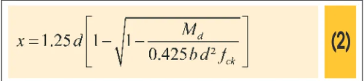
cross-section, normally denominated as bending design moment. The neutral axis position is determined from Equation 1. Solving such equation for x variable one obtains:
(2)
After the design of the reinforced concrete element, in which the tensile steel area is determined, the associated resistant bending moment, Mresist, is calculated by equilibrium conditions. Such
equi-librium results in:
(3)
(
)
2
0.408
resist w ck s sk
M
=
b x f
+
A f d x
-in which: fsk is the yield steel for longitudinal reinforcements.
The determination of shear strength in reinforced concrete struc-tures assumes as valid the hypothesis of generalized truss. It as-sumes stirrups positioned at 90º with the beam axis and spaced at each s. In addition to that, the shear resistance is determined considering the values of transversal reinforcement area Asw, concrete compressive characteristic strength fck (MPa), steel yield
for transversal reinforcement fyw (MPa), bw and d given in metre.
The shear resistance of a rectangular cross section, Vresist (kN),
belonging to a reinforced concrete beam is calculated by [16], considering the parameters described in the present paragraph, as follows:
(4)
Figur
1 – Rectangular cr oss-section of a rectangular reinforced concrete
e
It is important to mention that during the durability analysis, in which steel reinforcements area is lost along time, the neutral axis position, Equation 2, is updated at each time step. Therefore, as the reinforcements are corroded the neutral axis is recalculated. Another important remark that must be mentioned concerns the safety coeicients for design. The hyperstatic beam analysed in this study was designed considering safety coeicients. Then, the steel reinforcements areas were determined considering safety coeicients on the concrete and steel strengths and on the loading actions. Nev-ertheless, the probabilistic analyses were carried out disregarding such safety coeicients. Therefore, the characteristic values for all variables were considered during the probabilistic analyses.
2.2 Fick’s law
Reinforcement’s corrosion due to chloride ingress occurs in the pres-ence of oxygen. Such process stars when the chloride concentration at the rebar contours exceeds a threshold level causing depassiv-ation. Even for well-constructed and controlled reinforced concrete structures, a gradual ingress of chloride content from the external sur-face into concrete pores may occur according to the environmental conditions of aggressiveness. The transport mechanisms responsible for chlorides movement into concrete are capillary absorption, perme-ability under pressure, ion migration and ionic difusion [4]. Among them, the most signiicant contribution is attributed to the ionic difu-sion. Therefore, the proposed models, in literature, to represent such phenomenon are based, normally, only into ionic difusion.
Fick’s law [17] is an approach that has been widely used to simu-late chloride penetration and its transport through concrete pores [7, 14, 15, 18, 19, 20]. It is important to mention that Fick’s laws for difusion assumes the media in which the low occurs as ho-mogeneous, isotropic and chemically inert. In addition to that, the chloride low is assumed to be identical along all directions and constant along time. Considering concrete, these hypotheses are not completely satisied, because concrete is well known as het-erogeneous, anisotropic and chemically reactive (continued hy-dration and micro-cracking process) material. However, the meth-ods commonly adopted for chlorides transportation modelling in concrete consider this process governed only by ionic difusion. Then, it assumes that the concrete cover is completely saturated. Therefore, it makes the hypotheses of Fick’s laws acceptable for the chloride ingress modelling, because, in this case, the mate-rial is assumed completely saturated, with unidirectional chloride lux, i.e., from the exterior surface into the concrete depth. When chloride difuses into concrete, a change in chloride concentration,
C, occurs at any time, t, in every point, y, of the concrete, i.e., it is
a non-steady state of difusion. To simplify its analysis, the difu-sion problem is considered as one-dimendifu-sional. Many engineering problems of chloride ingress, as those discussed in this study, can be solved considering this simpliication.
For a semi-ininite domain with an uniform luid concentration at the external surface, the second Fick’s law can be written as fol-lows [13-15, 17]:
(5)
In which: C(y,t) is the chloride concentration at a given depth y and at a time t; C0 is the chloride concentration at the external surface assumed
constant in time; erfc is the complementary Gauss error function; D0 is the material difusion coeicient considered constant along time. From Equation 5, assuming that y is the concrete cover thickness
and C(y,t) the chloride concentration threshold, required to
elimi-nate the chemical protective layer of reinforcements, it is possible to determine the time for corrosion start tr as follows:
(6)
During the corrosion process caused by chloride difusion, two dif-ferent phases are observed. The irst one, called initiation period, is deined from the construction until the rebar depassivation. The second phase, denominated propagation period, involves the end of initiation period until the structural collapse. The boundary be-tween these two phases is the point characterized by the time of corrosion starts, which is evaluated by Equation 6 [14, 15].
2.3 Steel area reduction as a function of time
After the start of reinforcement corrosion, the rebar cross-section area reduces until its complete deterioration deining the propaga-tion period. In literature, there are few mathematical models to rep-resent such period as most researches consider as structural life only the initiation period. However, the propagation period can be modelled by empirical equations based on Faraday’s laws. Accord-ing to this approach, the reduction on the rebar cross-section area along time, assuming uniform corrosion process, is determined by the following equation [7, 21]:
(7)
( )
initialr
d
d t
ì
set t
set t
£
r= í
0.0232
(
)
initial corr r
d
-
i
t t
-
>
î
In which: d(t) and dinitial are the rebar diameter given in millimetres
for actual and initial conigurations, respectively; icorr is the corro-sion ratio given in µA/cm²; tr is the time for corrosion initiation given
in years and calculated according to Equation 6; t is the difusion
time, given in years.
Diferent parameters have inluence on the intensity of corrosion or into its rate. Among them, the water-cement ratio w/c and the cover depth y have to be mentioned. In order to account the inluence of such
pa-rameters, the corrosion ratio is expressed according to [22] as follows:
(8)
2.4 Steel yield strength reduction as a function of time
during corrosion process. Du et al. [23] performed an experimental study aiming to determine the mechanical residual strength of cor-roded steel rebar located into reinforced concrete elements. The researchers observed that the decrease on the yield stress oc-curs faster than the reduction of rebar diameter. According to [23], the reduction of the steel yield stress along time can be evaluated based on the following empirical expression:
(9)
in which: fy,t e fy,0 are the yield stress for corroded and non-corroded
steel rebar at a given time, respectively; Qcorr is the amount of
rein-forcements corrosion given as a percentage of material mass loss. The amount of corrosion is calculated, according [23], as follows:
(10)
In which: icorr is given in µA/cm² and calculated by Equation 8; the
diameter is provided in millimetres and the times in years.
3. Reliability model
3.1 General Concepts
The reliability analysis aims at calculating the probability of fail-ure regarding a speciic failfail-ure scenario, known as limit state. It is worth to note that reliability R and probability of failure Pfare complementary concepts, in which R=1- Pf.
The irst step in the reliability assessment is to identify the basic set of random variables
[
1, 2,...,]
T n
X = x x x for which uncertainties
have to be considered. For all these variables, probability distribu-tions are attributed to model its randomness. These probability dis-tributions may be deined by physical observations, statistical stud-ies, laboratory analysis and expert opinion. The number of random variables is an important parameter to determine the computing time consumed during the reliability analysis. To reduce the size of the random variable space, it is strongly recommended to consider as deterministic all variables whose uncertainties lead to minor ef-fects on the value of the probability of failure.
The second step consists in deining a number of potentially criti-cal failure modes. For each of them, a limit state function G X
( )
separates the space into two regions: the safe domain, where
( )
0G X > and the failure domain, whereG X
( )
<0. The boundarybetween these two domains is deined byG X
( )
=0, known as the limit state itself.The probability of failure is evaluated by integrating, over the fail-ure domain, the joint density function, [21]:
(11)
In which fX
(
x x1, 2,,xn)
is the joint density function of thevari-ables X. As the evaluation of the above integration is impossible in practice, as the joint density function has not an explicit form, alternative procedures have been developed on the basis of the concept of reliability index, β, or simulation methods [24, 25]. In the present study, the Monte Carlo simulation method was applied to evaluate the probability of structural failure for each individual failure mode. Such approach will be presented in the following section.
3.2 Monte Carlo simulation
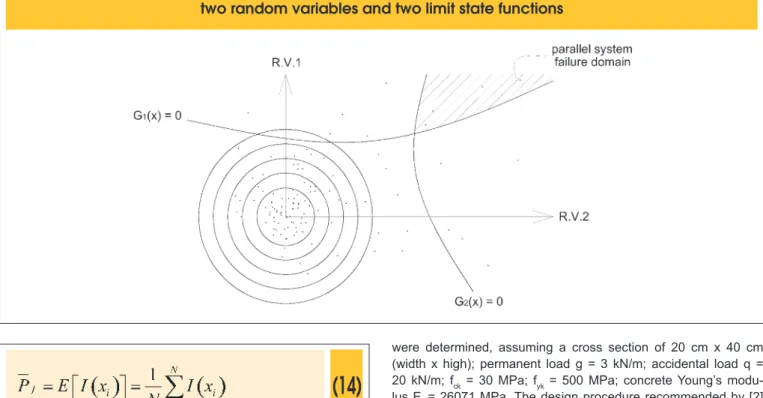
Monte Carlo method is a numerical simulation procedure widely used in reliability problems. In this method, a sampling of ran-dom variables is used to construct a set of values aiming to de-scribe the failure and safe spaces in order to calculate Eq. (11). The sampling is constructed based on the statistical distribution assigned for each random variable considered in the problem. As this method deals with simulation of the limit state function, as bigger be the sampling adopted more accurate will be the spaces’ description and more accurate will be the probability of failure achieved. The kernel of this method consists on the construction of a sampling for the random variables involved in the problem, as described in Figure 2.
Figure 2 presents a general sampling scheme assuming two random variables and two limit state functions. The simula-tion leads to the structural failure when the considered point is located at the failure domain. Otherwise, safety condition is observed. Series schemes consider failure if at least one limit state function be violated. On the other hand, parallel schemes assume failure condition when a set of critical limit state func-tions are violated. Such set of limit state funcfunc-tions are deined according to the structural system analysed and the failure paths available.
In spite of simulation methods be applicable for reliability analysis, optimization approaches such as First Order Reli-ability Methods (FORM) and Second Order ReliReli-ability Methods (SORM) are also available. FORM and SORM are based on the determination of the reliability index, which is associated to the probability of failure.
The probability of failure is calculated, for Monte Carlo simulation, using the following equation:
(12)
The function I
( )
xi can be estimated as follows:(13)
By simulating the limit state function for a convenient range of sam-pling, the mean value of I
( )
xi will be an estimator for the(14)
The disadvantage of this method is related to the high number of simulations required to compute accurately the probability of ure. Normally, in order to estimate accurately the probability of fail-ure of
10
−n, the number of simulations must be higher than10
n+2or
10
n+3. It means, in engineering structures, where the probabilityof failure is in between 3
10
− to10
−6, it is required10
5 to10
9 real-izations of the limit state function. When complex numerical me-chanical models are involved, which lead to high computational time, this method may be not reliable. However, theoretically, when the number of simulations tends to ininity, the probability of failure calculated tends to its real value. Other details about Monte Carlo simulation can be found in [24-27].4. Studied problem
4.1 Structure deinition
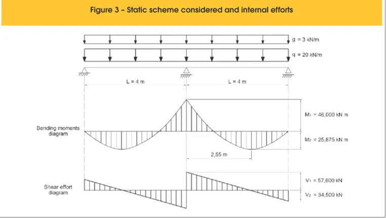
The presented methodology was applied to the probabilistic anal-ysis of a hyperstatic beam. Such beam is supported into three points, and the external load is composed by an uniform distributed load. Figure 3 illustrates the static scheme of the beam. The bend-ing moment and shear efort diagrams are also presented. The reliability analyses were carried out considering the critical ef-forts presented in Figure 3. The intensity of such eef-forts is deined as follows:
(15)
The analysed beam was designed, i.e. the reinforcements areas
were determined, assuming a cross section of 20 cm x 40 cm (width x high); permanent load g = 3 kN/m; accidental load q = 20 kN/m; fck = 30 MPa; fyk = 500 MPa; concrete Young’s modu-lus Ec = 26071 MPa. The design procedure recommended by [2] was followed. In addition to that, the following parameters were considered for durability analysis: environmental aggressiveness class III (industrial type with high risk of structure deterioration [2]); concrete cover thickness 4 cm. It is important to stress that the structural design considered safety factors. However, the proba-bilistic analyses were carried out disregarding all safety factors on the load and material properties.
After such considerations, the structure was designed and detailed as shown in Figure 4.
It is worth to mention that in this study serviceability limit states were not accounted.
4.2 Safety Evaluation. Mixed model considered
and efort redistribution
The reliability theory describes hyperstatic structural systems as redundant systems. Such description appears since the system failure, in this case, occurs after the failure of a number of indi-vidual modes equal to the structural hyperstatic degree. Conse-quently, as more than one limit state must be violated to the global failure be observed, such systems are subjected to load distribu-tion, ensuring higher safety level when compared to simple iso-static schemes.
Considering the studied beam, the global collapse occurs after the consecutive failure of at least two individual failure modes. The fail-ure is assumed when the efort due to the external load, Equation 15, exceeds the structural mechanical capacity given by Equations 3 and 4, in a given cross-section.
It is important to mention that hyperstatic structures presents more than one failure path, i.e. due to the load distribution and the com-bination of diferent random variables, the global failure can oc-cur according to diferent sequences of individual failure modes. In such cases, the reliability theory based on system approach aims to determine the probability of each individual failure mode as well as the probability of global structural failure. As a result, this approach predict the most probable failure path and the most prob-able mechanical mechanism of failure.
In order to apply the reliability theory based on system approach it
is convenient to construct a tree of failure. The strategy of tree of failure is commonly used in literature to indicate all possible failure paths. Therefore, by determining the probability of failure on each branch, the probability of global failure is determined as well as the most probable failure path.
To construct the tree of failure, individual failure modes must be deined. In the present study, three individual failure modes were considered. Two failure modes are related to bending whereas
one relates shear. The bending failures are due to the maximum negative and positive bending moments M1 and M2, respectively.
Such bending moments are represented in Figure 3 and occur at the central support (negative moment) and along the beam’s span (positive moment). The shear failure is due to V1, which occur at
the cross-section next to the central support.
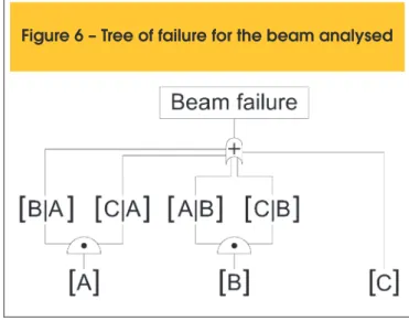
Therefore, the tree of failure was constructed considering three limit states: failure [A] deined by the bending failure on point A,
forts
failure [B] deined by the bending failure on point B and failure [C] deined by shear failure on point A. The points A and B are illus-trated in Figure 5 whereas Figure 6 presents graphically the tree of failure.
The irst level of the tree presented in Figure 6 describes only in-dividual failure modes [A], [B] and [C]. The second level accounts the conditional failure modes, i.e. the modes observed only after the occurrence of one individual mode. Therefore, in the second level, the conditional failure modes are written as follows: [B|A], [C|A], [A|B] and [C|B]. As observed in Figure 6, it is assumed that the individual failure mode [C] leads to the global failure. As previ-ously commented, shear failure has brittle mechanical behaviour. Then, the occurrence of such individual failure mode leads to the mechanical collapse of some structural components; the efort re-distribution is not available in such cases and collapse is observed. The tree of failure, which is used to illustrate the system approach with reliability theory, may be composed by failure mechanisms associated in parallel or series manner. The system adopted in the beam analysed in this study is mixed, as it is composed by a parallel sequence (initial failure by bending) connected to a series sequence (initial failure due to shear efort), [27]. Assuming that each failure path is a mutually exclusive event, the probability of global failure Pf,syst is obtained by the sum of the probabilities of failure on each path, as follows:
(16)
To formulate the reliability problem, the following limit state func-tions were considered:
(17)
1 rA aA
G
x
=
M
-
M
( )
2 rB aB
G
x
=
M
-
M
( )
3 rA aA
G
x
=
V
-
V
In which: Mr and Ma are, respectively, the resistant bending moment
and the bending moment due to the loading. concerns the limit state function, in terms of bending moments, for point A, whereas indicates the limit state function, in terms of bending moments, for point B. Vr and Va are the resistant shear efort and the shear force
due to the loading, respectively. indicates the limit state function,
in terms of shear, for point. The resistant eforts are obtained con-sidering Equations 3 and 4. The eforts due to the applied load are obtained using Equations 15.
4.3 Efort redistribution. Hypothesis assumed
It is important to mention that the initial static scheme presented in Figure 3 is valid for the determination of the irst individual failure mode, i.e. events [A], [B] and [C] on the tree of failure. After the irst individual failure mode be violated, efort redistribution may be assumed.
As previously mentioned, shear failure is brittle and normally leads to the structural collapse. Therefore, when the irst individual fail-ure mode violated is the mode [C], structural failfail-ure is assumed. However, the irst individual failure being modes [A] and [B], which characterize bending failures, efort redistribution has to be per-formed.
If individual failure mode [A] is irstly observed, a perfect plastic hinge is assumed to appear at point A. The mechanical efect of such new condition is introduced by reapplying the diference between the bending moment due to the external load and the resistant bending moment at point A, which characterizes a new static scheme. Then, in this new static scheme, the positive bend-ing moments and shear eforts considerbend-ing the exceedbend-ing bendbend-ing moment at point A are recalculated along the beam and the failure of the conditional failure modes is assessed.
When the irst individual failure mode observed is [B], irst level on the tree of failure, a perfect plastic hinge is introduced at point B.
Figure 5 – Failure modes defined by the respectively cross-sections
Analogously to performed for point A, the diference between the bending moment due to the external load the resistant bending moment is reapplied into the structure. Then, considering this new static scheme, the bending moment at point A and the shear eforts along the beam span are recalculated in order to assess the viola-tion of the condiviola-tional failure modes.
The corrosion modelling was performed considering the propa-gation phase, i.e. the reinforcements area and yield stress are penalised after the corrosion time initiation. For each time step increment, the rebar area and yield stress are determined using Equation 7 and 9, respectively. After applying the corrosion efects, the limit state functions are recalculated in order to determine the failure path at each time increment (irst individual failure mode and the conditional mode). As a result of such procedure, the in-dividual probabilities of failure and the probability of global failure are assessed. Is important to emphasize that the internal stresses derived from the expansive corrosion reactions and the adherence loss between steel were not considered in the present study.
5. Results and discussion
The random parameters adopted in the probabilistic analyses are presented in Table 1. In addition to such parameters, it was also
considered the following information, which were assumed as deterministic:
n Water-cement ratio: 0.50;
n Chloride concentration for reinforcements depassivation,
C(y,t): 0.90 kg/m3 [22];
n Chloride concentration at the beam surface, C0: 2.95 kg/m3 [22]; n Concrete difusion coeicient: [22];
n Total time considered in the analysis: 20 years;
n Time increment to evaluate the strength capacity due to corro-sion: 0.1 years;
n Total number of Monte Carlo simulations: 3x10⁶.
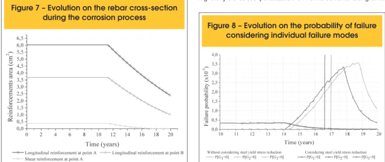
Figure 7 illustrates the evolution of reinforcement area along time. Due to corrosion phenomena, reinforcement area is lost along time. As illustrated in this igure, the reinforcement depassivation occurs after 11 years of the beam construction. From that time, de-nominated time for corrosion initiation, the corrosion propagation period starts. Then, the reinforcement area is penalized according to Equation 7. It is important to stress that reinforcement diameter reduction along time has linear behaviour, as presented in Equa-tion 7. Consequently, the area reducEqua-tion along time has quadratic behaviour.
Figure 8 presents the evolution of the probability of failure consid-ering each individual failure mode along time. In this igure, the probabilistic analyses were carried out accounting and disregard-ing the yield stress penalization on reinforcements along time.
Table 1 – Statistic properties for random variables
V.A. Distribution Mean Std. deviation Unit
fck Normal 30000.0 8000.0 kN/m²
fyk (longitudinal reinforcements) Lognormal 500000.0 50000.0 kN/m² fyk (transversal reinforcements) Lognormal 600000.0 60000.0 kN/m²
q Normal 3.0 0.345 kN/m
g Gumbel 20.0 4.3 kN/m
Figure 7 – Evolution on the rebar cross-section
during the corrosion process
In order to do not disserve the visualization of the results illustrated in Figure 8, the probabilities of failure only in the range 10 to 20 years are considered.
It is important to emphasize that, regarding Figure 8, the probability of failure of each initial failure mode changes along time. There-fore, the most probable failure path is not the same during all the time, as the most probable initial individual failure mode changes along time.
In the beginning of the propagation time, the most probable initial failure mode is [A]. Such type of failure is, initially, obvious as the cross-section positioned at point A required the higher amount of reinforcement’s area. However, as the corrosion process proceeds along time, the most probable failure scenario change. As present-ed in Figure 8, after 14 years of the beam construction, the failure mode [C] becomes the most probable initial failure mode. Such probabilistic behaviour is explained due to the stirrups diameter be lower than the longitudinal reinforcements diameter. Therefore, as presented in Equation 7, the stirrups lose cross-section area faster than longitudinal reinforcements along time. As a result of such cross-section lost, the failure on stirrups become more prob-able. This type of probabilistic behaviour illustrates the relevance/ importance of the present study. It shows that the mechanical be-haviour intended during design phase may not be observed during the structural life. The mechanical structural behaviour can change drastically when corrosion efects are accounted. As presented in
Figure 8, sudden brittle failures due to shear efort may appear before the expected ductile bending failures.
After 16.5 years from the beam construction, the individual fail-ure mode [B] becomes the most probable initial failfail-ure mode, as presented in Figure 8. Such change is explained due to the lon-gitudinal reinforcements cross-section lost along time caused by corrosion. Thus, the faster decrease of the longitudinal reinforce-ment’s cross-section along time at point B in comparison with point A and stirrups increases signiicantly the importance of such initial failure mode. As the reinforcement area along the beam change due to the corrosion, the structural coniguration change, the re-sistant mechanisms change and, consequently, the failure modes also change.
Another important behaviour that must be commented concerns the reduction of the probabilities of failure in individual modes [A] and [C]. The probabilities of failure presented in Figure 8 re-late only the probability of failure of each individual failure mode. Therefore, conditional probabilities of failure were not considered in the construction of such igure. Then, it explains the reduction on individual failure modes [A], after 14.5 years, and [C], after 18.5 years. It is important to emphasize that at each time increment at least one individual failure mode had its individual probability of failure increased (during the propagation period obviously). It is consistent regarding probabilistic analyses and make consistent the analyses performed.
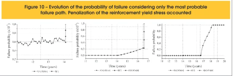
Figure 9 – Evolution of the probability of failure considering only the most probable failure path.
Penalization of the reinforcement yield stress disregarded
The penalization of the reinforcement yield stress as a function of time did not introduce signiicant change into the probabilistic mechanical behaviour of the beam along time. The subtle difer-ence concerns the time in which the mechanical efects due to the corrosion are observed. Considering the penalization of reinforce-ment yield stress, the mechanical efects of corrosion are observed earlier in comparison with analyses where such penalization was disregarded.
The behaviour of the probability of failure evolution along time re-garding only the most probable failure path can also be analysed, leading to interesting results. Figure 9 presents the evolution of the probability of failure along time considering only the most probable failure path and disregarding the penalization of the reinforcements yield stress. Figure 10 presents similar results but accounting the penalization of the reinforcements yield stress.
The main diference among the results presented in Figure 9 and 10 relates the time in which the mechanical corrosion efects are observed. When the penalization of the reinforcements yield stress is accounted, the mechanical corrosion efects are earlier observed, as expected. However, any change is observed into the most probable failure paths, which are the same.
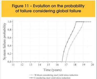
Figure 11 illustrates the evolution of the probability of global failure along time. According to this igure, it can be observed important increase on the probability of global failure from, approximately, 16 years. Such global probabilistic behaviour indicates, as presented in Figures 9 and 10, that in this age, the mechanical efects due to the corrosion change the most probable failure path. The re-duction on the reinforcements cross-section provided by corrosion phenomenon reduces the structural resistance. Consequently, the probability of global failure grows. It is important to observe that the probability of global failure always increase during the propagation period, which is consistent.
6. Conclusions
The main conclusions of the present study are the following:
n The penalization on the reinforcement yield stress along time introduces mechanical degradation earlier than the case in which such penalization is disregarded. However, any change was observed regarding the structural global failure path. Then, the importance of considering such penalization concerns the extension of propagation period, which is lower when penaliza-tion is considered. In spite of its simplicity as the penalizapenaliza-tion model is based on empirical observations, the coupling of this approach in a nonlinear mechanical framework may lead to important changes into the mechanical structural behaviour.
n The main conclusion of the present study concerns the change on the structural failure mode along time. The corrosion pro-cess provides reduction on the reinforcement’s cross-section area along time. Then, the structural resistance changes along time as well as the initial failure mode and the struc-tural collapse path. The knowledge about the most probable failure mode has major importance into a structural design, especially if maintenance, safety and failure prevention are focused. Considering a reinforced concrete structural design, bending moments and shear eforts lead to the determination of longitudinal reinforcements and stirrups areas, respectively. Then, the structural cross-sections more requested by the
ex-ternal load receive higher reinforcement area. The structural engineer, intuitively, expects that the irst failure mode occurs at the cross-section with higher reinforcement ratio, as such cross-sections are more requested. However, during the cor-rosion process, reinforcements area are lost, as previously mentioned. In addition to that, the corrosion process has more severe consequences in cross-sections with lower reinforce -ment ratios, as presented in the results of the present study. Then, during the corrosion phase, failure modes expected dur-ing design phase normally does not occur and failure modes in cross-section with lower reinforcement ratio appear. Therefore, the change on the failure modes during the propagation pe-riod is an important phenomenon that must be accounted in durability analyses in reinforced concrete structures in order to avoid unexpected failure modes.
Finally, the present study supports further investigations that in-corporates nonlinear mechanical models for concrete and steel, in order to consider realistic approaches to the eforts redistribution. Furthermore, the coupling of the probabilistic model to an optimiza-tion approach may also be interesting to determinate the optimal design solution that includes initial costs, maintenance and repair costs due to the change on the failure modes along time.
7. Acknowledgment
Sponsorship of this research project by São Paulo Research Foun-dation (FAPESP), grant number 2014/18928-2 is greatly appreci-ated. This research is a part of the activities scheduled by the re-search project USP/COFECUB 2012.1.672.1.0.
8. Bibliography
[1] MEHTA, P. K.; MONTEIRO, P. J. M. Concreto: microestru-tura, propriedades e materiais. Ibracon, São Paulo, 3ed., 2008, 674 p.
[2] ASSOCIAÇÃO BRASILEIRA DE NORMAS TÉCNICAS. NBR 6118. Projeto de estruturas de concreto, Rio de Janei-ro, 2014.
[3] HELENE, P. R. L. Corrosão em armaduras para concreto armado. Pini/IPT, São Paulo, 1986.
[4] CASCUDO, O. O controle da corrosão de armaduras em concreto: inspeção e técnicas eletroquímicas. São Paulo: Pini; Goiânia: Editora UFMG, 1997.
[5] APOSTOLOPOULOS, C. A.; PAPADAKIS, V. G. Conse-quences of steel corrosion on the ductility properties of rein-forcement bar. Construction and Building Materials, v. 22, n. 12, 2008, p. 2316-2324.
[6] BASTIDAS-ARTEAGA, E.; SCOEFS, F.; STEWART, M. G.; WANG, X. Inluence of global warming on durability of cor-roding RC structures: a probabilistic approach. Engineering Structures, v. 51, 2013, p. 259–266.
[7] VAL, D. V.; STEWART, M. G. Life-cycle cost analysis of re-inforced concrete structures in marine environments. Struc-tural Safety, v. 25, 2003, p. 343–362.
[8] SAMSON, E.; MARCHAND, J.; SNYDER, K. A. Calculation of ionic difusion coeicients on the basis of migration test results. Materials and Structures, v. 36, 2003, p. 156–165. [9] SAMSON, E.; MARCHAND, J. Modeling the efect of
tem-perature on ionic transport in cementitious materials. Ce-ment and Concrete Research, v. 37, 2007, p. 455–468. [10] BASTIDAS-ARTEAGA, E.; SÁNCHEZ-SILVA, M.;
CHA-TEAUNEUF, A.; RIBAS-SILVA, M. Coupled reliability model of biodeterioration, chloride ingress and cracking for rein-forced concrete structures. Structural Safety, v. 30, 2008, p. 110-129.
[11] ZHAO, Y.; YU, J.; JIN, W. Damage analysis of cracking mod-el of reinforced concrete structures with rebar corrosion. Cor-rosion Science, v. 53, 2011, p. 3388–3397.
[12] FRANGOPOL, D. M.; LIN, K-Y.; ESTES, A. C. Reliability of reinforced concrete girders under corrosion attack. Journal of Structural Engineering, ASCE, v. 123, n. 3, 1997, p. 286– 297.
[13] NOGUEIRA, C. G.; LEONEL, E. D.; CODA, H. B. Reliability algorithms applied to reinforced concrete structures durabil-ity assessment. IBRACON Structures and Materials Journal, v. 5, n. 4, August, 2012, p. 440-450.
[14] NOGUEIRA, C. G.; LEONEL, E. D. Probabilistic models ap-plied to safety assessment of reinforced concrete structures subjected to chloride ingress. Engineering Failure Analysis, v. 31, 2013, p. 76–89.
[15] LIBERATI, E. A. P.; NOGUEIRA, C. G.; LEONEL, E. D.; CHATEAUNEUF, A. Nonlinear formulation based on FEM, Mazars damage criterion and Fick’s law applied to failure assessment of reinforced concrete structures subjected to chloride ingress and reinforcements corrosion. Engineering Failure Analysis, v. 46, 2014, p. 247-268.
[16] CARVALHO, R. C.; FIGUEIREDO FILHO, J. R. Cálculo e de-talhamento de estruturas usuais de concreto armado segundo a NBR 6118:2003 – 3ed. – São Carlos: EdUFSCar, 2009. [17] CRANK, J. The mathematics of difusion. 2ed. Oxford
(Lon-don): Clarendon Press; 1975, 414 p.
[18] GUZMÁN. S.; GÁLVEZ, J. C.; SANCHO, J. M. Cover crack-ing of reinforced concrete due to rebar corrosion induced by chloride penetration. Cement and Concrete Research, v. 41, 2011, p. 893–902.
[19] BASTIDAS-ARTEAGA, E.; CHATEAUNEUF, A.; S
AN-CHEZ-SILVA, M.; BRESSOLETTE, P.; SCHOEFS, F. A
comprehensive probabilistic model of chloride ingress in un-saturated concrete. Engineering Structures, v. 51, 2011, p. 259–66.
[20] VAL, D. V.; CHERNIN, L.; STEWART, M. G. Experimen -tal and numerical investigation of corrosion-induced cover cracking in reinforced concrete structures. Journal of Struc -tural Engineering, ASCE, v. 135, 2009, p. 376–385.
[21] VAL, D. V.; MELCHERS, R. E. Reliability of deteriorating RC slab bridges. Journal of Structural Engineering, ASCE, v. 123, n. 12, 1997, p. 1638–1644.
[22] VU, K. A. T.; STEWART, M. G. Structural reliability of con-crete bridges including improved chloride-induced corrosion models. Structural Safety, v. 22, n. 4, 2000, p. 313-333. [23] DU, Y. G.; CLARK, L. A.; CHAN, A. H. C. Residual capac
-ity of corroded reinforcing bars. Magazine of Concrete Re-search, v. 57, n. 3, April, 2005, p. 135-147.
[24] NOWAK, A. S.; COLLINS, K. R. Reliability of structures, Bos-ton: McGraw-Hill, 2000.
[25] ANG, A. H-S.; TANG, W. H. Probability Concepts in Engi-neering: Emphasis on Applications to Civil and Environmen-tal Engineering, 2nd Edition. New York: John Wiley & Sons, 1984.
[26] SANTOS, K. R. M. Técnicas de amostragem inteligente em simulação de Monte Carlo. São Carlos, 2014, Dissertação (Mestrado) – Escola de Engenharia de São Carlos, Univer-sidade de São Paulo, São Paulo, 191 p.