Multiple flaws are frequently occurred in actual components, such as pressure vessels and power plants. These flaws will in some circumstances lead to more severe effects than single flaw alone. Assessment of the interaction behavior is based on the evaluation of alignment and combination of these multiple flaws. In the cur rent standards, multiple cracks are treated as an equivalent single crack if the distance between two cracks satisfies a prescribed criterion. First, this study introduces the current alignment and combination rules for through wall cracks. Following, to investi gate the effects of the interaction of cracks, brittle fracture of a plate containing two offset cracks is simulated. The effect of cracks distances and crack lengths on stress intensity factors is evaluated. In addition, crack growth behavior is simulated based on linear elastic fracture mechanics approach. The extended finite element method has been utilized to model the problem. This method enables the domain to be modeled by finite elements without explicitly meshing the crack surfaces, and hence crack propagation simulations can be carried out without remeshing. Based on the results, a new alignment and combination rule is proposed.
crack interaction, crack growth, extended finite element method, brittle fracture.
! " #
a PhD Candidate, Faculty of Mechanical Engineering, K.N. Toosi University of Technology, Tehran, Iran
E mail: [email protected] b Prof., Faculty of Mechanical Engineer ing, K. N. Toosi University of Technolo gy, Tehran, Iran
http://dx.doi.org/10.1590/1679 78251664
$ %"&' % &
Combination rules Alignment rules
Standard/codes
≤ max (2 , 2 ) ≤ 12.5 mm
ASME
≤ max (2 , 2 ) Growth ≤ 10 mm ≤ 5 mm
≤ 2 > 5 Fracture: ≤ 12.5 mm JSME
≤ + < 0: ≤ ( + )
> 0: ≤ ( + )& ≤ ( + ) API 579
≤ min (2 , 2 ) ≤ ( + )
BS 7910
≤ max (2 , 2 ) ≤ 0.5 min (2 , 2 )
WES 2805
≤ min (2 , 2 ) ≤ min (2 , 2 )
GB/T 19624
≤ min (2 , 2 ) ≤ ( + )
R6
≤ min (2 , 2 ) ≤ ( + )
A16
≤ min (2 , 2 ) ≤ ( + )
FKM
Interaction rectangles Interaction rectangles
RSE M
≤ min (2 , 2 ) ≤ min (2 , 2 )
FITNET
cracks treatment rules for through wall cracks in the fitness for service codes.
Extensive studies have been conducted to understand the effect of multiple crack interaction and to reduce the conservativeness in the current assessment procedures. In addition, many approaches have been developed to provide insights on the interacting effect of multiple cracks under linear elastic fracture mechanics (LEFM). Some analytical models have been proposed for the problem of a linear elastic solid with multiple cracks. Yokobori et al. (Yokobori, Uozumi, & Ichikawa, 1971) based on the concept of continuous distribution of infinitesimal dislocations, studied two equal length offset cracks in an infinite elastic solid. Sadowski et al. (Sadowski, Marsavina, Peride, & Craciun, 2009) formulated a new analytical model in order to investigate the interaction of two collinear cracks in an orthotropic elastic material. The solutions are restricted to special geometries.
Other approaches such as finite element method (Serier, Belhouari, & Bachir Bouiadjra, 2004), fi nite element alternating method (Kamaya, 2008) and body force method (Murakami & Nemat Nasser, 1982) have been developed to provide insights on the interacting effect of multiple cracks. However, these works focused on the calculation of stress intensity factors. The condition of crack coalescence for offset cracks is often studied experimentally due to the difficulty of simulation of the crack growth process. Hasegawa et al. (Hasegawa, Saito, & Miyazaki, 2009) performed fracture ex periments on carbon steel plates with two nonaligned flaws and proposed a new alignment rule for linear elastic fracture mechanics evaluation. Miyazaki et al. (Miyazaki, Hasegawa, Saito, & Bezensek, 2009) conducted fracture tests on flat plate specimen with non aligned flaws at ambient temperature and investigated the effects of the flaw separation and flaw size on the maximum load. Although many attempts have been done to study the interaction of multiple cracks, but it is an open problem. Some FFS codes have been revisited in recent years. The reason for revision of FFS codes is to reduce the margin of conservativeness of these codes to extend the component life and reduce the costs of the component replacement. This reason justifies the new studies of interacting cracks and revision of FFS codes. This has been done based on new simulations, new softwares, new tools, and new methods that were not available before. Certainly, extended finite element method (X FEM) is an appropriate tool for handling huge computations and crack growth simulations.
In the present study a new application of X FEM is developed for simulating the growth of multiple interacting cracks in a brittle material. The model developed based on the principles of mixed mode fracture mechanics, provides a rational explanation for the phenomenon of crack inter action, and predicts the coalescence conditions. The X FEM allows the entire crack to be represent ed independently of the finite element mesh, and so remeshing is not necessary to model crack growth. So, in this study, the interaction between two non aligned parallel through wall cracks is investigated considering their length, distance between planes and crack tip separation. The values of mode I and mode II stress intensity factors are evaluated by X FEM analysis and the effect of stress intensity factor interaction on fracture behavior is studied. In addition, the crack growth sim ulation is developed using the X FEM and propagation paths of two interacting cracks have been determined. The interaction is considered by the occurrence of coalescence. Based on the simulation results, new alignment and combination rules are proposed for linear elastic fracture mechanics
( )% ' ' % * % %+&'
The extended finite element method (X FEM) proposed by Moës et al. (Moës, Dolbow, & Belytschko, 1999) proved to be a very efficient tool for the numerical modeling of crack propagation in LEFM. In the X FEM, a discontinuous function and the two dimensional asymptotic crack tip displacement fields are added to the finite element approximation to account for the crack using the notion of partition of unity. This allows the representation of crack discontinuities independently of the mesh. The method does not require any remeshing for crack growth. The extended finite ele ment approximation for the displacement is expressed as:
( ) = " #$( )%$
$∈'
+ " #(( ) ( ))(
(∈*
+ " #+( ) ," -.( )/+.
0
.1
2
+∈3
where is the set of all nodes in the mesh; is the classical degree of freedom at node ; is the shape function associated with node ; ⊂ is the subset of nodes that are enriched for the crack discontinuity and are the corresponding additional degrees of freedom; the nodes in are such that their support intersects the crack but do not contain any of its crack tips; and ⊂ is the subset of nodes that are enriched for the crack tip. The corresponding additional degrees of freedom are /+., l=1, …, 4, for the crack tip; the nodes in are such that their support contain the crack tip. The function (#) is a discontinuous function across the crack surface and is constant on each side of the crack: +1 on one side of the crack and −1 on the other. The near tip functions -.(#);
=1, ..., 4 are given by
4-.(5, 6)7, 8 = 1 … 4 = ;√5= >62 , √5?@=62 , √5= >62 = >6, √5?@=62 = >6A (2)
where ( θ) are the local polar co ordinates at the crack tip. The variational formulation of the boundary value problem is given by
B C ∶ EF GH
I
= B J. EF GH
I
+ B K̅. EF GM
NO
(3)
where σ is the stress tensor, εεεε is the strain tensor, and b and K̅ are the body force and external trac
tion vectors, respectively. is the domain and Γ is traction boundary. Discretization of Eq.3 and applying X FEM displacement approximation (Eq. 1) results in a discrete system of linear equilib rium equations:
) 4 (
P = Q
where $ is the stiffness matrix, is the vector of degrees of nodal freedom (for both classical and enriched ones) and is the vector of external force. The element contribution to K and f are as follows:
P$(R = S
P$(TT P$(TU P$(TV
P$(UT P$(UU P$(UV
P$(VT P$(VT P$(VV
W (5)
Q$X= YQ$T Q$U Q$V Q$V Q$VZ Q$V0[\ (6)
where the submatrices and vectors that appear in Eq. (5) and Eq. (6) are defined as:
P$(]^= B(_$])` a _(^ GΩ (5, = = u, a, b)
Q$T= B #$K̅ GΓ + B #$/ GΩ ef
hi (8)
Q$U= B #$ K̅ GΓ + B #$ / GΩ ef
hi
(9)
Q$Vj = B #$kjK̅ GΓ + B #$kj/ GΩ ef
hi
(10)
In Eq. 7, % is the constitutive matrix for an isotropic linear elastic material, and _lT, _lU, and _lV are the matrix of shape function derivatives which are given by
_m = n
om,p q
q om,r
om,r om,p
s (11)
_m)= n
(omt),p q
q (omt),r
(omt),r (omt),p
s (12)
_m/= u_m/v _/wm _m/x _m/yz (13)
_m/{= n
(om|{),p q
q (om|{),r
(om|{),r (om|{),p
s (} = 1, 2, 3, 4) (14)
For the elements cut by a crack, the standard Gauss quadrature points are insufficient for numeri cal integration. The elements that are cut by a crack are subdivided into sub triangles which do not cross the crack and the element quadrature is performed over these sub triangles. Therefore, the number of gauss integration points is increased for the elements that have been enriched.
, & - % % & & #%" ## % # %. %&"# ' " /"&0%+ *.# #
•€ و • = B ‚ƒ
$(( )„…„† + ƒ$ $(( )„…„† − ˆ$ ( , )E(‰„†„Š
(
‹ GŒ
(15)
where (1) are the actual fields of the problem approximated by the X FEM solution and (2) are the auxiliary fields. These fields are chosen to be the asymptotic crack tip fields for pure mode I or pure mode II to compute and , respectively. In Eq.(15), are the local directions with respect to the crack tip, δ Ž is the Kronecker’s delta and is an arbitrary and continuous function that must vanish at the outer boundary of the problem domain and take the value 1 at the crack tip. The SIFs of the problem are then calculated as follows:
•' =•2‘•( ,’“]R ”•–R ') •''=•2‘•( ,’“]R ”•–R '') (16)
where ′= for plane stress and ′= / (1ν2) for plane strain.
The function used in this work is an annular weighting function which takes value =1 for nodes contained in a circle of radius measured from the crack tip, and =0 for the remaining nodes. For additional details on the evaluation of the SIFs in the X FEM, see (Moës et al., 1999).
For the prediction of the crack growth direction, the MTS criterion (maximum tangential stress) (Erdogan & Sih, 1963) is used, which means that the crack will propagate from its tip in a direction θ so that the circumferential stress σθθ is maximum.
6—= 2 5?˜ > ‚ −2•''/•'
1 + š1 + 8(•''/•') ‰ (17)
where θc is the angle that will follow the crack for each of the crack increments. θ is measured with respect to a local polar coordinate system with its origin at the crack tip and aligned with the direc tion of the existing crack. The sign convention is such that θ when > 0 and vice versa. The equivalent mode I stress intensity factor is calculated using the growth angle θ
•'Rœ = •'?@=Z•62 ž − •— ''32 ?@=Z•62 ž sin (6— —) (18)
This can then be compared to the critical value for the material and crack growth is said to occur if
•'Rœ≥ •— (19)
1 " * # * % &
In this section, the X FEM simulation of two offset cracks on the flat plate is investigated for differ ent parametric studies. Two types of simulations are carried out: In the first, the specimen is sub jected to the fixed tensile stress, and stress intensity factors are extracted for different parameters. The specimen in the second type is subjected to displacement control loading, and the growth path of two cracks and their coalescence are analyzed for different conditions.
12$2 ' 3
The tensile specimen shown in Fig. 2 is employed for X FE analysis. The model is a representation of a plate with two non aligned through wall cracks. Tensile static load is applied to this plate and brittle fracture was assumed. The mechanical properties of specimen are shown in Table 2.
! " Illustration of plate geometry with two nonaligned through wall cracks.
Mechanical property value
Young’s modulus, (GPa) 200
Yield strength, σ (MPa) 304
Tensile strength, σ (MPa) 449
Poisson’s ration, ν 0.3
Fracture toughness, (MPa√m) 28.2
Elongation % (min.) 18
The width and wall thickness of the specimen are 160 mm and 5.7 mm, respectively. The length of the specimen is 800 mm. The plate is loaded by a uniform stress in the vertical direction. The plane strain condition is assumed, and a two dimensional X FE model has been defined, as depicted in Fig. 3.
! " Numerical model and mesh detail around two offset cracks with enriched nodes.
The structured mesh consists of 9435 quadrilateral elements. This level of discretization is found to yield a converged solution (results are within 1% of those for a 10000 elements). The mesh is refined to the centre of the plate to obtain more accuracy in the domain of crack propagation. It is inde pendent of the crack geometry and the same mesh is used throughout the simulation. The great advantage of extended finite element method is using a fixed mesh in all performed simulations. Because of a high number of performed analyses, this method is very convenient particularly in the crack growth analysis and tremendously reduces the time of the analysis.
When cracks are dissimilar in length, the larger crack (2 1) is susceptible to fracture. The larger
crack is assumed to have constant length, 2 1=20 mm. In the analysis, the effects of different values
of the out of plane crack separation ( ), the in plane crack separation ( ), the direct distance be tween two cracks (!), and the length of smaller crack (2 2) on the stress intensity factors and crack
growth path is evaluated. Based on the physics of the problem and according to FFS rules present ed in Table 1, new dimensionless variables are defined for parametric analysis of the problem, and the effects of these variables on the variation of stress intensity factor of the cracks and crack coa lescence are analyzed:
∗
= 2 ∗
= 2 (20)
In order to obtain more detailed interactions, the mode I stress intensity factor at inner tip of larger crack (Fig. 2: point A) is extracted. The " is normalized by the stress intensity factor and is referred to "*= # . Note that is the stress intensity factor for an isolated crack with the length of 2 under normal remote stress. In this problem the length of first crack is assumed to be fixed, equal to 2 1=20 mm, the length of second one (2 2) is selected as a variable and the analyses
12(2 4
To verify the X FEM model, both two and three dimensional standard finite element analyses were carried out using the code Abaqus. Quarter point collapsed elements were introduced at the crack tip to model the stress field singularity. For the 2 D FE model the element type CPS8 (8 node quadratic plane stress) and for the 3 D FE model the type C3D20 (20 node quadratic brick) is used. For comparison of results, a special specimen (2 1=2 2=20 mm, = =10 mm i.e. *= *=0.5) is
subjected to a prescribed tensile load on its top edge equal to 10000 N/m, and its bottom edge is fixed. The material is identical to the one considered in Table 2. The 2 D FE mesh consists of 3371 elements and 10294 nodes. The 3 D FE mesh consists of 11392 elements and 55153 nodes. The 2 D and 3 D FE meshes used in Abaqus conform to the crack surface. In order to capture singularity at the crack tip, the mesh around the crack tip is needed to be considerably refined. The FE meshes and deformed shapes of the specimen are shown in Fig. 4 and Fig. 5. Also, Fig. 6 shows the normal ized mode I stress intensity factor distribution along thickness for 3 D FE model in Abaqus. It seems that this parameter is approximately fixed along thickness direction. Table 3 compares the results of FE models and X FE model. The results of X FE model are consistent with the 2 D and 3 D FE models. It seems that this model could be used for further simulations.
Model. Order of
elements
No. of elements
No. of nodes
No. of DOFs
Max. displacement
Normalized stress intensity factor "*
2 D X FE linear 9435 9710 19420 4.033×10⁸ 1.134
2 D FE quadratic 4371 11294 22588 4.034×10⁸ 1.138
3 D FE quadratic 11392 55153 165459 4.033×10⁸ 1.136
Comparison of the results of different models.
(b)
! " FE models created in Abaqus (a) 2 D mesh (b) 3 D mesh.
(a)
(b)
! " Deformed shape of the FE models in Abaqus (a) 2 D FE model (b) 3 D FE model.
! " & Normalized mode I stress intensity factor distribution along thickness for 3 D FE model in Abaqus. 1.11
1.12 1.13 1.14 1.15 1.16
0 1 2 3 4 5 6 7 8 9 10
Node along thickness direction
N
o
rm
a
li
ze
d
s
tr
e
ss
in
te
n
si
ty
f
a
ct
o
r,
KIA
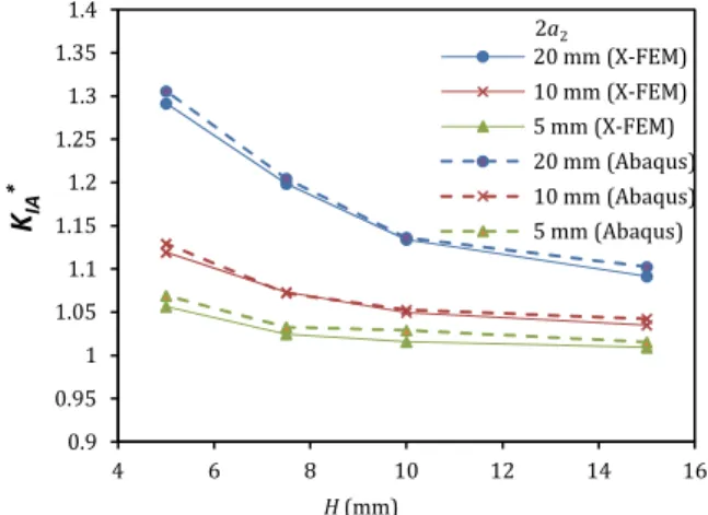
To ensure the accuracy of the proposed extended finite element model (X FEM), normalized mode I SIFs versus different vertical crack distance are calculated for different values of second crack length and compared with the results of 2 D FE model (Abaqus software). Modeling stationary cracks using FEM needs the geometry of cracked body to be matched with the mesh. Therefore, for each case, a separate FEM model is constructed.
Figure 7 shows good correlation between the calculated SIFs at the crack tip using 2 D FEM and X FEM. The difference between the X FEM and Abaqus results in all cases is less than 2 percent.
! " ' Validation of X FEM model with Abaqus results.
12,2 '
Figs. 8 10 show the influence of the normalized vertical ( *) and horizontal ( *) distances on the interaction of stress intensity factor "* at the inner tip of larger crack (point A). In the analyses, the normalized vertical ( *) and horizontal ( *) distances take the following values:
∗= 1.5, 1.0, 0.9, 0.7, 0.5, 0.3
∗ = 1.5, 1.2, 1.0, 0.9, 08, 0.7, 0.6, 0.5, 0.4, 0.3, 0.2, 0.1, 0, −0.2
! " ( Normalized mode I stress intensity factor distribution at inner tip of larger crack for similar offset cracks (2 =2 =20 mm).
0.9 0.95 1 1.05 1.1 1.15 1.2 1.25 1.3 1.35 1.4
4 6 8 10 12 14 16
20 mm (X-FEM) 10 mm (X-FEM) 5 mm (X-FEM) 20 mm (Abaqus) 10 mm (Abaqus) 5 mm (Abaqus)
H(mm)
2a2
KIA
*
0.9 0.95 1 1.05 1.1 1.15 1.2 1.25 1.3 1.35 1.4
-0.2 0 0.2 0.4 0.6 0.8 1 1.2 1.4
KIA
*
S*
1.5 1 0.9 0.7 0.5 0.3
! " Normalized mode I stress intensity factor distribution at inner tip of larger crack for dissimilar offset cracks (2 =20 mm, 2 =10 mm).
! " Normalized mode I stress intensity factor distribution at inner tip of larger crack for dissimilar offset cracks (2 =20 mm, 2 =5 mm).
The figures show that the mode I stress intensity factor at the inner tip of larger crack increases as the nearest crack tips approach one another, but then declines as the tips pass. As is clear from these figures, the general shape of the curves and their values in the three figures, are approximate ly located in the same range. Another important point is that in high *, although the normalized in plane crack separation ( *) decreases, the stress intensity factor does not exceed a certain limit. For example, according to Fig. 8, in *=1.5, the stress intensity factor in comparison with an iso lated crack, is maximally increased about 4%.
0.95 1 1.05 1.1 1.15 1.2
-0.2 0 0.2 0.4 0.6 0.8 1 1.2 1.4
1.5 1 0.9 0.7 0.5
S*
H*
KIA
*
0.9 0.95 1 1.05 1.1 1.15 1.2
-0.2 0 0.2 0.4 0.6 0.8 1 1.2 1.4
1.5 1 0.9 0.7 0.5
S*
KIA
*
1212 # *
Figs. 11 13 show that normalized mode I stress intensity factors are almost in the same range for different secondary crack length. This indicates that the normalized first mode stress intensity fac tor is an appropriate factor for describing the interaction effect. According to figure 12 in *= 1.0, the increase in the stress intensity factor in comparison with an isolated crack, is about 7%. Fur thermore, maximum increase occurs when the lengths of two cracks are equal. According to figure 13, in * = 0.9, the maximum increase in the stress intensity factor for the length of second crack 2a2=20 mm is 8.5 % and for 2 2=10 mm is 8 %, and at the length of secondary crack 2 2=5 mm is
equal to 6.5%. "*
! " Comparison of normalized mode I stress intensity factor at inner tip of larger crack for different secondary crack length ( *=1.5).
! " Comparison of normalized mode I stress intensity factor at inner tip of larger crack for different secondary crack length ( *=1.0).
0.9 0.92 0.94 0.96 0.98 1 1.02 1.04 1.06
-0.2 0 0.2 0.4 0.6 0.8 1 1.2 1.4 20 mm 10 mm 5 mm
S* KIA
*
2a 2
0.9 0.92 0.94 0.96 0.98 1 1.02 1.04 1.06 1.08
-0.2 0 0.2 0.4 0.6 0.8 1 1.2 1.4 20 mm 10 mm 5 mm
S* KIA
! " Comparison of normalized mode I stress intensity factor at inner tip of larger crack factor for different secondary crack length ( *=0.9).
The crack interaction and coalescence is most relevant to the mixed mode loading condition. The extent of / ratio depends on the offset distance. Figs. 14 and 15 indicate that the mode II stress intensity factor ( ) is introduced when the nearest crack tips closely approach; the crack tips then actually experience a mixed mode I and II condition during their interaction.
! " The ratio of mode II to mode I stress intensity factor at inner tip of larger crack factor for different secondary crack length ( *=0.9).
0.9 0.92 0.94 0.96 0.98 1 1.02 1.04 1.06 1.08 1.1
-0.2 0 0.2 0.4 0.6 0.8 1 1.2 1.4 20 mm 10 mm
5 mm
S* KIA
*
2a 2
-16 -14 -12 -10 -8 -6 -4 -2 0 2
-0.2 0 0.2 0.4 0.6 0.8 1 1.2 1.4
20 mm 10 mm 5 mm
S*
1
0
0
×
KII
/
KI
! " The ratio of mode II to mode I stress intensity factor at inner tip of smaller crack factor for different secondary crack length ( *=0.9).
The mode II stress intensity factor becomes significant and the sign changes from positive to nega tive as the crack tips approach and then pass. The absolute value of / is larger for the inner tip of smaller crack.
The direction of crack growth under combined mode I and II loading is only related to the / ratio (Eq. (17)). The positive value of / promotes a divergent path while its negative value a convergent one. The above results indicate that it is the mixed mode stressing condition experienced by the nearest tips of the offset cracks that leads to the change of crack growth direc tion and causes coalescence.
1252 / # 6
In order to obtain detailed information about the interaction behavior of offset cracks, crack growth simulation is carried out for different configuration of cracks. In the analyses, the normalized verti cal ( *) and horizontal ( *) distances take the following values:
∗= 1.5, 1.0, 0.9,0.7, 0.5, 0.3
∗= 1.5, 1.2,1.0, 0.9, 08, 0.7,0.6, 0.5, 0.4,0.3, 0.2, 0.1,0, −0.2
In the simulation, plate specimen is subjected to displacement controlled loading and the crack path is determined according to procedure described in the previous section. In each configuration, the growth behavior is determined and it is specified whether propagating cracks run into the opponent crack or not. The crack paths obtained by the simulation for two configurations of cracks are shown in Figs. 16 and 17. Figure 16 shows the results for the specimen in which *=0.75, *=0.75 and 2 2=20 $$. In this case, the cracks grow to each other and coalescence of the crack tips would
occur. Figure 17 shows the result for the specimen in which *=1.5, *=1.5 and 2 2=10 $$. In this
case, the inner flaws did not grow significantly because the distance between the flaw tips is large. Finally, coalescence of the crack tips did not occur. Also, Table 4 presents the crack propagation paths of X FEM simulation for some configurations.
-35 -30 -25 -20 -15 -10 -5 0 5 10
-0.2 0 0.2 0.4 0.6 0.8 1 1.2 1.4 20 mm 10 mm 5 mm
S*
1
0
0
×
KII
/
KI
No. Crack length
($$) ($$)
* ($$) * Fracture path
coalescence
A 01 30 1.5 30 1.5 No
A 02 2 1=20 20 1 20 1 Yes
A 03 2 2=20 15 0.75 15 0.75 Yes
A 04 10 0.5 10 0.5 Yes
B 01 20 2 20 2 No
B 02 2 1=20 15 1.5 15 1.5 No
B 03 2 2=10 10 1.0 10 1.0 No
B 04 7.5 0.75 7.5 0. 75 Yes
C 01 15 3.0 15 3.0 No
C 02 2 1=20 10 2.0 10 2.0 No
C 03 2 2=5 5 1.0 5 1.0 No
Cracks paths results: X FEM simulation.
! " & Simulated crack propagation paths for similar offset cracks ( *=0.75, *=0.75, 2 1=20 $$ 2 2=20 $$).
Simulation results of crack propagation paths for different configuration of offset cracks indicate that the coalescence of the crack tips will occur when the increase in the mode I stress intensity factor in comparison with an isolated crack is about 7% or greater, and the ratio of the mode II to mode I stress intensity factor at the tip A is more than 1%.
According to Figures 8 10 and 14, it could be concluded that for equal offset cracks (2 1=2 2), the
following conditions are satisfied when *≤
1 and *≤
1. For dissimilar offset cracks (2 1≠2 2), these
conditions are satisfied when *< 1 and *< 1. This could be a boundary for alignment and combi nation criteria for offset cracks.
1272 ' 6 6 3 % "6
In order to assess the proximity rules in the FFS codes, the treatment of these codes is compared with the X FE simulation results for some configurations in Table 5.
In the ASME and JSME codes, an absolute value is used for the alignment rule and the vertical distance is compared with a fixed separation distance of 12.5 mm. This implies that the interac tion is not taken into account even though the interaction is important for large cracks. According to Table 5, the two cracks in A 02 and A 03 specimens are regarded as two non aligned independ ent cracks (TNIC) in accordance with the ASME and JSME Codes; whereas the simulation results indicate that the cracks run in to each other. On the other hand, the two cracks in B 03, C 02 and C 03 specimens are regarded as aligned and combined cracks which this is not consistent with the simulation results. It can be asserted that the vertical distance should be a function of the size of cracks. However, in these codes, the combination rule is defined in terms of the larger crack. Com pared to simulation results, this rule gives conservative evaluation.
In the API 579 the vertical distance is compared with the average of two crack lengths as the alignment rule. Also, in the BS 7910, FKM, R6 and A16 the direct distance ! is compared with the average of two crack lengths as the alignment rule. These codes, especially API 579, give overly conservative results compared to the simulation results, particularly, if the opponent crack is small. In the API 579, the two cracks of the specimens B02, B 03, C 02 and C 03 are treated to be aligned and combined as one single crack (OSC) as opposed to the simulation results, where the cracks did not run to each other. In these codes, the horizontal distance between two cracks is compared with the minimum crack length. It seems to be a reasonable criterion.
No. Crack length (mm) (mm)
Fracture path coalescence (X FEM results) ASME &
JSME API 579
BS7910, R6,
A16 & FKM WES 2805
GB/T 19624 &
FITNET Proposed rules
A lig nm en t C om bi na ti on R es ul te d cr ac k A lig nm en t C om bi na ti on R es ul te d cr ac k A lig nm en t C om bi na ti on R es ul te d cr ac k A lig nm en t C om bi na ti on R es ul te d cr ac k A lig nm en t C om bi na ti on R es ul te d cr ac k A lig nm en t C om bi na ti on R es ul te d cr ac k
A 01 30 N N TNIC N TNIC N TNIC N TNIC N TNIC N TNIC
A 02 2 1=20 20 Y N TNIC Y Y OSC N TNIC N TNIC Y Y OSC Y Y OSC
A 03 2 2=20 15 Y N TNIC Y Y OSC N TNIC N TNIC Y Y OSC Y Y OSC
A 04 10 Y Y Y OSC Y Y OSC Y Y OSC Y Y OSC Y Y OSC Y Y OSC
B 01 20 N N TNIC N TNIC N TNIC N TNIC N TNIC N TNIC
B 02 2 1=20 15 N N TNIC Y Y OSC N TNIC N TNIC N TNIC N TNIC
B 03 2 2=10 10 N Y Y OSC Y Y OSC Y Y OSC N TNIC Y Y OSC N TNIC
B 04 7.5 Y Y Y OSC Y Y OSC Y Y OSC N TNIC Y Y OSC Y Y OSC
C 01 15 N N TNIC N TNIC N TNIC N TNIC N TNIC N TNIC
C 02 2 1=20 10 N Y Y OSC Y Y OSC Y N TCC N TNIC N TNIC N TNIC
C 03 2 2=5 5 N Y Y OSC Y Y OSC Y Y OSC N TNIC Y Y OSC N TNIC
Abbreviations: Y: Yes; N: No; OSC: One single crack; TCC: Two co planar cracks; TNIC: Two non aligned independent cracks.
Comparison of proximity rules among different codes.
In the GB/T 19624 and FITNET codes, the vertical distance between two cracks is compared with the minimum crack length as the alignment rule and the horizontal distance is compared with the minimum crack length as the combination rule. The evaluation of cracked geometries with these codes match with the simulation results in the most cases. The alignment rules defined by GB/T 19624 and FITNET give conservative evaluation only in some cases (B 03 and C 03). These codes seem to be reasonable criteria.
It is clear that, for two identical co planar cracks, almost all the current FFS codes prescribe that a single enveloping crack with a length of 2 =4 + should be adopted if the condition of
/ < 2 is satisfied. However, for two dissimilar co planar cracks, the combination rule is different in various FFS codes. For example, for two interacting cracks with 1=2 2, the combination rule in
BS7910, R6, A16, FKM, FITNET, GB/T19624 is / 2< 2, which is less than that of / 2< 3 in
API579 and less than that of / 2< 4 in ASME code. The combination rules for co planar cracks
As can be seen in Table 5, it seems that the proposed alignment and combination rules are in accordance with the X FE simulation results and these rules could reduce the margin of conserva tiveness. This leads to more component life and less the costs of the component replacement.
& * # &
To investigate the effects of the interaction of cracks, extended finite element method has been uti lized to simulate the brittle fracture of a plate containing two offset cracks. The effect of crack dis tances and lengths on the values of mode I and mode II stress intensity factors is evaluated. In ad dition, crack growth behavior is simulated based on linear elastic fracture mechanics approach. The mode I stress intensity factor at the inner tip of two offset cracks increases by decreasing distance between the two cracks, and decreases by decreasing opponent crack length) The mode II stress intensity factor is introduced when the nearest crack tips closely approach; the crack tips then ac tually experience a mixed mode I and II condition during their interaction. The mode II stress in tensity factor becomes significant and the sign changes from positive to negative as the crack tips approach and then pass. Simulation results of crack propagation paths indicate that the coalescence of the crack tips will occur when the increase in the mode I stress intensity factor in comparison with an isolated crack is about 7% or greater, and the ratio of the mode II to mode I stress intensity factor at the tip A is more than 1%. According to simulation results, the following conditions are satisfied when *≤
1 and *≤
1 for equal offset cracks (2 1=2 2), and when *< 1 and *< 1 for dis
similar offset cracks (2 1≠2 2). Therefore, the following alignment and combination rules are pro
posed for LEFM assessment:
Alignment rule: ¥ ≤ 2< min(2 1, 2 2) 2 1≠ 2 2
1 2 1= 2 2§
Combination rule: ¥ ≤ 2< min(2 1,2 2) 2 1≠ 2 2
1 2 1= 2 2§
! "
This research received no specific grant from any funding agency in the public, commercial or not for profit sectors.
*
None declared.
"
AFCEN. (2005) RSE M: Inservice Inspection Rules for the Mechanical Components of PWR Nuclear Islands. Paris: French Association for design, construction and in service inspection rules for nuclear island components.
API. (2007) API 579 1/ASME FFS 1: Fitness for Service: American Petroleum Institute.
ASME. (2010). Boiler and Pressure Vessel Code Section XI Rules for Inservice Inspection of Nuclear Power Plant Components. New York: American Society of Mechanical Engineers.
BS. (2005) BS 7910: Guide to Method for Assessing the Acceptability of Flaws in Metallic Structures. London: Brit ish Standards Institution.
Commissariat a L’Energie Atomique. (2002) A16: Guide for Defect Assessment and Leak Before Break Analysis. France.
CS. (2004) GB/T19624: Safety Assessment for In Service Pressure Vessels Containing Defects. Beijing: Chinese Standards.
Erdogan, F., & Sih, G. (1963). On the crack extension in plates under plane loading and transverse shear. Journal of basic engineering, Vol. 85, pp. 519.
European Fitness for Service Network. (2008) FITNET Fitness for Service (FFS) – Procedure: Eds. M. Koçak, S. Webster, J.J. Janosch, R.A. Ainsworth, R. Koers.
FKM. (2004) Fracture Mechanics Proof of Strength for Engineering Components. Frankfurt am Main: Forschungs kuratorium Maschinenbau (FKM).
Hasegawa, K., Saito, K., & Miyazaki, K. (2009). Alignment Rule for Non Aligned Flaws for Fitness for Service Eval uations Based on LEFM. Journal of Pressure Vessel Technology, Vol. 131, No. 4, pp. 041403.
Jones, R., Atluri, S., Pitt, S., & Williams, J. (1995). Developments in the analysis of interacting cracks. Engineering Failure Analysis, Vol. 2, No. 4, pp. 307 320.
JSME. (2004) Codes for Nuclear Power Generation Facilities: Rules of Fitness for Service for Nuclear Power Plants: Japan Society of Mechanical Engineers.
Kamaya, M. (2008). Influence of the Interaction on Stress Intensity Factor of Semielliptical Surface Cracks. Journal of Pressure Vessel Technology, Vol. 130, No. 1, pp. 011406 011406.
Lam, K. Y., & Phua, S. P. (1991). Multiple crack interaction and its effect on stress intensity factor. Engineering Fracture Mechanics, Vol. 40, No. 3, pp. 585 592.
Miyazaki, K., Hasegawa, K., Saito, K., & Bezensek, B. (2009). Experimental Study of Ductile Fracture for Non Aligned Multiple Flaws in a Plate. Paper presented at the ASME 2009 Pressure Vessels and Piping Conference, Prague, Czech Republic.
Moës, N., Dolbow, J., & Belytschko, T. (1999). A finite element method for crack growth without remeshing. Inter national Journal for Numerical Methods in Engineering, Vol. 46, No. 1, pp. 131 150.
Murakami, Y., & Nemat Nasser, S. (1982). Interacting dissimilar semi elliptical surface flaws under tension and bending. Engineering Fracture Mechanics, Vol. 16, No. 3, pp. 373 386.
Sadowski, T., Marsavina, L., Peride, N., & Craciun, E. M. (2009). Cracks propagation and interaction in an ortho tropic elastic material: Analytical and numerical methods. Computational Materials Science, Vol. 46, No. 3, pp. 687 693.
Serier, B., Belhouari, M., & Bachir Bouiadjra, B. (2004). Numerical study of the interaction between an interfacial crack and a subinterfacial microcrack in bi materials. Computational Materials Science, Vol. 29, No. 3, pp. 309 314. Tan, J. T., & Chen, B. K. (2013). A new method for modelling the coalescence and growth of two coplanar short cracks of varying lengths in AA7050 T7451 aluminium alloy. International Journal of Fatigue, Vol. 49, No. 0, pp. 73 80.
Wes. (1997) Wes 2805: Methods of Assessment for Defects in Fusion welded Joints with Respect to Brittle Fracture and Failure due to Fatigue Crack Growth: The Japan Welding Engineering Society.
Yau, J. F., Wang, S. S., & Corten, H. T. (1980). A Mixed Mode Crack Analysis of Isotropic Solids Using Conserva tion Laws of Elasticity. Journal of Applied Mechanics, Vol. 47, No. 2, pp. 335 341.