Guilherme Ornelas Pimentel Meneses
Licenciatura em Engenharia BiomédicaElectron driven reactions in sulphur
containing biological prototypes
Dissertação para obtenção do Grau de Mestre em Engenharia Biomédica
Orientador: Doutor Filipe Ribeiro Ferreira da Silva,
Investigador Pos-Doc, Universidade Nova de Lisboa
Júri:
Electron driven reactions in sulphur containing biological
proto-types
Copyright © Guilherme Ornelas Pimentel Meneses, Faculdade de Ciências e Tecnologia, Universidade Nova de Lisboa
Acknowledgements
I would like to express my special appreciation and thanks to my advisor Dr. Filipe Ferreira da Silva, for his constant support, encouragement and for the opportunity he has given me to visit and work with an international group. You have been a tremendous mentor for me.
Prof. Dr. Janina Kopyra, for her supervision, discussion and assistance while and after working at the Siedlce University.
Prof. Dr. Paulo Limão-Vieira for the immense knowledge and guidance through-out these years. Special thanks to Diogo Almeida for all the help, availability and laughs. Tiago Cunha for the fruitful discussions, hard work and friendship through the several stages of this thesis.
I thank all of the remaining members of the research group, particularly Dr. Susana Sério, Juscelino Ferreira and Emanuele Lange.
NANO-IBCT for providing me with financial support for the STSM. To the Depart-ment of Physics of the New University of Lisbon, CEFITEC, and Siedlce University for providing me the necessary working conditions.
My cousin Diogo, Paulo and his colleagues for their help and availability.
My closest colleagues and friends from UNL, not only for the much-valued friend-ship but also for all the great moments shared over the years.
To my dedicated parents, for the unconditional support.
Abstract
The interaction of ionising radiation with living tissues may direct or indirectly generate several secondary species with relevant genotoxic potential.
Due to recent findings that electrons with energies below the ionisation thresh-old can effectively damage DNA, radiation-induced damage to biological systems has increasingly come under scrutiny. The exact physico-chemical processes that occur in the first stages of electron induced damage remain to be explained. How-ever, it is also known that free electrons have a short lifetime in the physiological medium. Hence, electron transfer processes studies represent an alternative ap-proach through which the role of "bound" electrons as a source of damage to biological tissues can be further explored.
The thesis work consists of studying dissociative electron attachment (DEA) and electron transfer to taurine and thiaproline. DEA measurements were executed in Siedlce University with Prof. Janina Kopyra under COST action MP1002 (Nano-scale insights in ion beam cancer therapy). The electron transfer experiments were conducted in a crossed atom(potassium)-molecule beam arrangement.
In these studies the anionic fragmentation patterns were obtained. The results of both mechanisms are shown to be significantly different, unveiling that the damaging potential of secondary electrons can be underestimated. In addition, sulphur atoms appear to strongly influence the dissociation process, demonstrat-ing that certain reactions can be controlled by substitution of sulphur at specific molecular sites.
Keywords: dissociative electron attachment, electron transfer, taurine, thiaproline,
Resumo
A interacção da radiação de alta energia com o meio biológico produz diversas espécies secundárias com potencial genotóxico relevante. Estudos recentes de-monstram que electrões com energia abaixo do limiar de ionização são altamente eficientes no que diz respeito à criação de quebras na estrutura do ADN e ARN. Os processos físico-quimicos que ocorrem nos primeiros instantes de interacção dos electrões não são totalmente conhecidos. É sabido que os electrões livres têm um curto tempo de vida no meio biológico, passando a existir em estados solvatados. Assim, estudos do processo de transferência de electrão são uma alternativa capaz de desvendar o papel de espécies dadoras de electrões como precursores de dano em tecido biológico.
O objectivo deste trabalho é estudar padrões de fragmentação de compostos que contêm enxofre (taurina e tiaprolina) por transferência de electrão em coli-sões átomo(potássio)-molécula e por captura electrónica dissociativa (CED). As medidas de CED foram realizadas na universidade de Siedlce, Polónia, no grupo da Professora Janina Kopyra através da rede COST MP1002 (Nano-scale insights in ion beam cancer therapy) num aparalho de feixes de electrões e molecular cruzados.
Os padrões de formação de fragmentos aniónicos foram obtidos por ambas as técnicas. Os resultados revelaram diferenças significativas nos dois processos, sobretudo devido à influência do iãoK+no complexo de colisão após transferência
do electrão. Para além disso, a presença do átomo de enxofre nas moléculas estudadas condiciona o processo de dissociação, demonstrando que certas reacções podem ser controladas ao substituir o enxofre em ligações específicas da molécula.
Palavras-chave: captura electrónica dissociativa, transferência de electrão, taurina,
Contents
Contents xi
List of Figures xiii
List of Tables xv
Glossary xvii
1 Introduction 1
1.1 Motivation . . . 1
1.2 Thesis Outline . . . 4
2 Electron Driven Reactions 5 2.1 Indirect Damage By Free Electrons . . . 5
2.1.1 Introduction . . . 5
2.1.2 Dissociative Electron Attachment (DEA) . . . 8
2.1.3 Dynamics of anion formation . . . 9
2.2 Damage By Electron Transfer . . . 11
2.2.1 Introduction . . . 11
2.2.2 Atom-Atom Collisions . . . 13
2.2.3 Atom-Molecule Collisions . . . 17
2.3 State Of The Art . . . 20
3 Experimental Set-ups 23 3.1 Electron Transfer Experimental Set-up . . . 23
3.1.1 Apparatus Overview . . . 23
3.1.2 Projectile Beam . . . 24
3.1.3 Langmuir-Taylor Surface Detector . . . 26
3.1.4 Molecular Target Oven . . . 27
3.1.5 Time-of-Flight Mass Spectrometer . . . 27
3.2 Dissociative Electron Attachment Experimental Set-up . . . 32
3.2.1 Apparatus Overview . . . 32
3.2.2 Monoenergetic Electron Beam . . . 33
3.2.3 Ion Extraction and Detection . . . 35
3.2.4 Energy Scale Calibration . . . 36
3.2.5 Vacuum system . . . 36
4 Results and Discussion 37 4.1 Experimental Conditions . . . 37
4.1.1 Dissociative Electron Attachment Measurements . . . 37
4.1.2 Electron Transfer Measurements . . . 38
4.2 Taurine . . . 41
4.2.1 Dissociative Electron Attachment Results . . . 42
4.2.2 Electron Transfer Results . . . 46
4.2.3 Discussion . . . 52
4.3 Thiaproline . . . 53
4.3.1 Dissociative Electron Attachment Results . . . 54
4.3.2 Electron Transfer Results . . . 59
4.3.3 Discussion . . . 65
5 Conclusions and Future Work 67 5.1 Conclusions . . . 67
5.2 Future Work . . . 69
List of Figures
1.1 Chronological schematic of radiation effects on living beings . . . 2
2.1 Thermalization of electrons after being created . . . 6
2.2 Born-Oppenheimer potential energy diagram . . . 8
2.3 Classification of resonances . . . 10
2.4 Adiabatic and non-adiabatic potential energy curves . . . 15
2.5 Schematic of atom-atom scattering . . . 16
3.1 Schematic of the electron transfer experimental device . . . 25
3.2 Charge exchange system schematics . . . 26
3.3 Langmuir-Taylor detector . . . 27
3.4 Picture of the molecular target oven . . . 28
3.5 Single-stage TOF schematic . . . 28
3.6 Schematic of the implemented TOF mass spectrometer . . . 29
3.7 Voltages applied to TOF extraction system . . . 30
3.8 Schematic of the dissociative electron attachment experimental device 33 3.9 Trochoidal electron monochromator arrangement . . . 35
3.10 Quadrupole mass spectrometer arrangement . . . 36
4.1 Schematic representation of taurine molecule . . . 41
4.2 DEA to taurine: ion yield of (a)m/z124 and (b)m/z1 . . . 42
4.3 DEA to taurine: ion yield of (a)m/z46 and (b)m/z16 . . . 43
4.4 Possible dissociation pathways for (A and B)O− and (C)NH2− produc-tion after low-energy electron attachment to taurine . . . 44
4.5 Schematic representation of the stable conformer of taurine molecule . 45 4.6 Taurine TOF anion spectra at 30, 70 and 100 eV collision energies . . . 48
4.7 Schematic representation of thiaproline molecule . . . 54
4.8 DEA to thiaproline: ion yield of 132, 117, 105, 100, 88, 71, 61, 46 and 45m/z 55 4.9 DEA to thiaproline: ion yield of 32, 26, 17 and 16m/z . . . 56
List of Tables
4.1 Available energies in the centre-of-mass framework. . . 39 4.2 Experimental acquisition parameters registered for potassium-thiaproline
collisions. . . 40 4.3 Experimental acquisition parameters registered for potassium-taurine
collisions. . . 40 4.4 Resonance positions of the anionic fragments generated from DEA to
taurine. . . 43 4.5 Assigned anionic fragments in DEA and electron transfer to taurine. . 47 4.6 Resonance positions of the anionic fragments generated from DEA to
Glossary
π∗ πantibonding orbital.
σ∗ σantibonding orbital.
Khyper+ hyperthermal potassium ion.
Kther+ thermal potassium ion.
Khyper0 hyperthermal potassium atom.
Kther0 thermal potassium atom.
Rc crossing radius.
a.m.u. atomic mass units. AE appearance energy.
BDE bond dissociation energy. CEC charge exchange chamber. CPS cationic potassium source. DBS dipole bound state.
DEA dissociative electron attachment. DP deflecting plates.
EA electron affinity. ET electron transfer.
IE ionisation energy. LEE low energy electron.
LTD Langmuir-Taylor detector.
LUMO lowest unoccupied molecular orbital. m/z mass to charge ratio.
MO molecular orbital. MTO molecular target oven. NMR nuclear magnetic resonance. PO potassium oven.
QMS quadrupole mass spectrometer. SEM secondary electron multiplier. T taurine.
TEM trochoidal electron monochromator. TNI temporary negative ion.
TOF time-of-flight. TP thiaproline.
Chapter 1
Introduction
1.1
Motivation
Over the last decades, the scientific community has shown particular interest in better understanding the processes capable of damaging biological tissue, mainly those that may result in severe physiological pathologies. It soon became clear that the exposure of living tissue to ionising radiation (e.g., X-rays, γ-rays, α
particles, ions, protons and electrons) may eventually cause in the long term erratic DNA replication, cellular death, cancer and mutations, as a final result of several sequenced chemical and biological mechanisms triggered in the early stages of irradiation (approximately 10−6 s after interaction). Indeed, the direct
and indirect effects of ionising radiation are recognized as the main precursors of structural and functional cellular alterations [1].
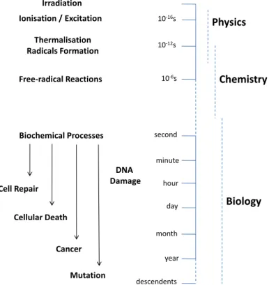
In figure 1.1 is presented a chronological schematic representing the different stages of cell damage in biological systems, from the instant of irradiation up to a time scale of several years. The initial instants of irradiation ( 10−6seconds) are
governed by physical processes, such as excitation and ionisation, followed by physical-chemical processes that may culminate in DNA lesions. In turn, DNA damage leads to a stage where biological processes may occur and cancer may be diagnosed, reaching the medical and health sciences [2]. As such, it is fair to state that to better understand in detail certain biological effects and ultimately avoid the mentioned physiological disorders, one needs to first unravel and eventually gain control over the processes originating such chain of events, i.e. the physical and physical-chemical processes. Such knowledge may also contribute to the development of more effective and accurate treatments.
10-16s
10-12s
10-6s
second Irradiation
Ionisation / Excitation
Thermalisation Radicals Formation
Free-radical Reactions
Biochemical Processes
Physics
Chemistry
minute
hour
day
month
year
descendents DNA
Damage Cell Repair
Cellular Death
Cancer
Mutation
Biology
Figure 1.1: Chronological schematic of radiation effects on living beings.
destroying cancer cells. However, such therapy is also responsible for damaging the surrounding healthy tissue. In addition to the knowledge based on macroscopic evidences, the understanding of the fundamental molecular mechanisms that follow radiation impact is thus a necessary prerequisite for a more effective and controlled radiotherapy strategy.
Over the past century, great research efforts have been made to better under-stand the direct and indirect effects of ionising radiation interaction with biological systems, especially DNA and other cellular components. Cancer related research is driven towards the study of such mechanisms [3]. Initially, it was thought that direct ionisation and attack by hydroxyl radicals (OH ) were the main precursors for double strand breaks in DNA. However, the majority of biological effects is not related to direct interactions with the biological material, but rather with secondary species resulting upon direct irradiation [1]. Such secondary species (e.g., ions, radicals and free electrons) may be potentially more damaging than the primary radiation. Actually, the results of Brunet al.[4] illustrate that when
the same amount of energy is deposited in DNA by photons or by low energy secondary electrons, the latter produces much more damage.
1.1. MOTIVATION
is not restricted to DNA, they being also effectively capable of damaging other structures present in the cellular medium, such as proteins [5]. DNA is directly packed and ordered by proteins called histones and is also expressed by other kind of proteins called transcription factors. Due to protein’s molecular and structural complexity, scientific studies rather focus on its building blocks, i.e. amino acids. Such studies intend to understand the fragmentation patterns of biomolecules upon dissociative electron attachment (DEA) processes.
Since free electrons have a short lifetime before being fully thermalized by the physiological medium, an alternative approach is to study a process that can mimic electron driven reactions in cellular medium conditions, such as the process of electron transfer (ET) from a donor atom to a biomolecule of interest. Both processes are capable of dissociating the molecule, generating multiple anionic and neutral fragments, and possibly causing its loss of functionality. Moreover, the products of the dissociation, including free radicals (H , OH and O ), can in turn induce further damage.
Because DNA is the most important molecular target in radiotherapy, LEEs genotoxic effects can result in higher sensitivity of tumour cells to radiation via two strategies: (1) making DNA more sensitive to LEEs through radiosensitizers and (2) increasing the number of LEEs near the DNA. Because low energy electrons have a range of about 5 times the diameter of the DNA helix and are created in large numbers, their damage can be confined within a short distance involving few biomolecules such as DNA of cancer cells and nearby water molecules and proteins [6].
In the same line of thought, sulphur containing nucleobases are also effectively used as anticancer drugs [7]. There is, however, lack of knowledge on the con-sequences to these molecules upon interaction with ionising radiation. As such, the scientific community has become more aware of the importance of studies on electron driven reactions to sulphur containing biological relevant molecules, in order to further investigate the role of sulphur atoms in such processes.
The core work was performed in Atomic and Molecular Collisions Labora-tory (CEFITEC, Department of Physics of FCT/UNL), in a crossed beam set-up designed to perform time-of-flight (TOF) mass spectrometric studies of negative ions, resulting from electron transfer processes in atom-molecule collisions. Ad-ditionally, DEA studies have been performed in the Department of Chemistry of Siedlce University in Poland, in close collaboration with Prof. Janina Kopyra within COST action MP1002 (Nano-IBCT: Nano-scale insights in ion beam cancer therapy). In order to conduct dissociative electron attachment to biomolecules studies, an electron-molecule crossed beam apparatus was used where the yielded negative ions were detected.
1.2
Thesis Outline
This thesis starts with a background chapter where the fundamental concepts of both dissociative electron attachment and electron transfer processes are described, followed by a section summarizing the main published research work within this context. The aim of the chapter is not to provide an exhaustive description of the theory, but rather an empirical summary of the theoretical concepts essential to understand the following chapters.
In chapter 3 the experimental set-ups are thoroughly described and its working principles explained. The apparatus where the electron transfer measurements were performed is addressed on the first section of the chapter. On the following section is given a portrayal of the apparatus designed to perform dissociative electron attachment measurements.
Chapter 4 comprises the results obtained and its analysis. The chapter includes two sections assigned for the two molecules studied. In each section the results of both measurements are presented separately along with a comparative discussion.
Chapter 2
Electron Driven Reactions
2.1
Indirect Damage By Free Electrons
2.1.1
Introduction
It is now known that one of the most abundant products of living tissue irradiation with ionising radiation are LEEs. In fact, for each MeV of deposited energy in bio-logical tissue, approximately 5×10⁴secondary electrons are produced [8]. Adding
to this, the evidences show that these electrons possess an energy distribution ranging from 0 eV to ~20 eV, most of them having energies lying below the typical ionisation threshold (~10 eV) of most organic molecules [9].
Secondary electrons generated by high quanta interaction with the biological system will gradually lose kinetic energy, until reaching near 0 eV energy and becoming trapped by electrostatic interaction with the induced and permanent dipoles of the surrounding biomolecules. At this stage, i.e. within a time scale of 10−12s, electrons can be considered as being thermalized and later they become
solvated [6]. Figure 2.1 represents a scheme of the thermalization process in energy, time and space scales. Aldrichet al.[10] studies revealed the importance of physical
fast processes in biological relevant molecules, i.e. electron attachment prior to solvation.
Irradiation
Ionisation M+ + e
-Electronic Excitation M*
Free Electron
Time (ps) Energy (eV)
30
20
6 0
0,1
Distance (nm)
0
Attachment M
-Solvated Electron e-(aq)
1
0
-3 1
10
Figure 2.1: Thermalization of electrons after being created by interaction of high energy quanta with the physiological medium: energy, time and space scales [1]
than the ionisation threshold (~10 eV) and even at energies lower than excita-tion energies (~3 eV) [12]. Boudaiffaet al.[8] and Lehnertet al.[13] even suggest
that 70% of the DNA damage is related to secondary low energy electrons, the remaining 30% being related to direct deposition of energy. By demonstrating that electron capture by DNA composing molecules is the main cause for the formation of single and double strand breaks in DNA chains within this energy range, Boudaiffaet al. [8] changed the paradigm of radiation induced damage,
since a new set of natural processes has to be taken into account.
Following Sanche’s work [8], several other dissociative electron attachment and theoretical studies were conducted, focusing mostly on different other biological relevant molecules such as nucleotides, sugar units and amino acids.
2.1. INDIRECT DAMAGE BY FREE ELECTRONS
The resulting molecular anion can react via the following channels:
e−+AB→(AB−)∗ →(AB)−+hv (2.1)
(AB−)∗ →(AB)∗+e− (2.2)
(AB−)∗ → A+B−orA−+B (2.3)
Wheree−represents the incident electron and ABa generic molecule.
Reaction 2.1 represents radiative stabilization of the TNI to its stable ground state, being capable of confining the extra electron. This reaction implies release of the excess internal energy by photon emission. Since radiate lifetimes are on the order of 10−9−10−8s, which is significantly higher than the latter processes, this
mechanism will not be able to compete with the other two presented channels, unless some external influence confines the electron in the vicinity of the molecule long enough for the anion to stabilize.
Another reaction channel, depicted in equation 2.2, refers to autodetachment of the extra electron from the TNI. As mentioned before, this mechanism can be both elastic and inelastic. In the latter case, the resulting molecule is left in an electronic or vibrational excited state.
The TNI lifetime varies on a large scale, depending on the size of the molecule and the resonance energy. According to Heisenberg’s uncertainty principle, the lifetime of a TNI is related to the energy width given by:
Γ ≈ ¯h
τ (2.4)
WhereΓis the energy width of the resonance, ¯hthe Planck constant andτ the
lifetime of the anionic state.
be also site and bond selective, i.e. the process can selectively occur depending if the electron is captured into specific regions of the molecule and specific chemical bonds [14, 15, 16, 17].
On the other hand, one should note that in addition to direct damage to cellular constituents, low energy electrons also have an indirect role. Indeed, secondary electrons may interact with other molecules present in the surrounding environ-ment and generate reactive species (ions, excited molecules and free radicals), which in turn are known to have the capability to efficiently damage DNA. Given that cells are 70% composed of water, radicals H , OH and O , products of H2O radiolysis, are proven examples of such significant role.
2.1.2
Dissociative Electron Attachment (DEA)
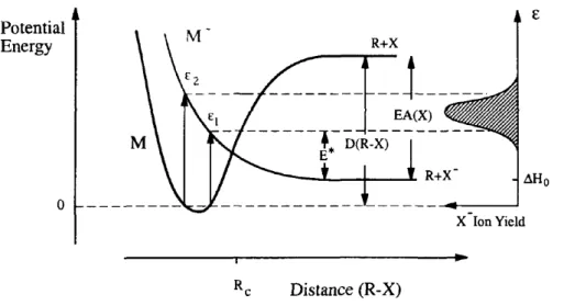
The process of dissociative electron attachment described in equation 2.3 can be pictured in a Born-Oppenheimer potential energy diagram, as depicted in figure 2.2. Such curves are only applicable to diatomic molecules, while for poly-atomic molecules they represent two-dimensional cuts through hyperdimensional surfaces along a reaction coordinate.
Figure 2.2: Born-Oppenheimer potential energy diagram associated with electron attachment and subsequent electronic dissociation. Adapted from [9].
2.1. INDIRECT DAMAGE BY FREE ELECTRONS
to compensate the bond dissociation energy, D(R-X). Hence, the lowest energy limit for DEA is given by:
∆H0 =D(R−X)−EA(X) (2.5)
Considering electronic transitions, one can make the approximation that they are most likely to occur without changes in the position of the nuclei involved. This approximation is known as the Franck-Condon principle and the transitions involved are called vertical transitions [18]. According to the Franck-Condon principle, transitions from the continuum state (M+e−(r→∞)) to the temporary
negative ion (M−) are only possible within the energy range betweenǫ1andǫ2
(figure 2.2).
Autodetachment can occur for internuclear distances smaller thanRc, which is
the crossing point of the two potential energy curves. For radius longer thanRc
the extra electron is bound to fragment X to a degree that autodetachment ofM−
is no longer possible.
On the right-hand side of figure 2.2 is shown the ion yield curve as a function of the incident electron energy (ǫ). The excess energy is represented in the same
figure asE∗, as well as the electron affinity (EA).
2.1.3
Dynamics of anion formation
In order for dissociation to occur, the extra electron must be somehow trapped to prevent immediate autodetachment. This subsection addresses the electronic configuration of the temporary negative ions in resonant electron attachment.
If the electron is captured without changing the electronic configuration of the target molecule, i.e. if the extra electron is added into one of the unoccupied virtual MOs, one speaks of a single particle (1p) resonance. On the other hand, if the electron attachment is accompanied by an electronic excitation of the molecule, meaning that two electrons will be in normally unoccupied MOs, the resonance is called core excited or two particle one hole (2p-1h) resonance.
If the energy of the core excited resonance lies above that of the excited neutral (the parent electronic state), the resonance is called open channel core excited resonance. However, if it lies below, one refers to a closed channel or Feshbach resonance. The latter implies a much longer lifetime of the anion, since the parent excited state cannot be reached any more.
effective interaction potential between the electron and the neutral molecule. For that reason, such resonances are called shape resonances. The effective interaction potential is the combination between the charge-induced polarization potential for long-range interaction and the repulsive centrifugal potential at shorter dis-tances, where electron-electron repulsion dominates. Such combination results in a potential barrier where an electron can eventually be trapped. However, these resonances have short lifetimes since the electron can escape by tunnelling through the barrier.
At low energies vibrational Feshbach resonances (VFR) can occur. This trapping mechanism is likely to take place in molecules having a very large dipole moment (>2.5D) leading to a long-range attractive interaction. The extra electron becomes
trapped in a very diffuse orbital whose dimensions are very large when compared to the size of the resulting ion core (Rydberg-like orbital), on the positive side of the dipole, resulting in an anion with a geometry similar to the neutral. Hence, the anionic state is also called dipole bound state (DBS) [19]. In free electron attachment, these states are only accessible if release of the excess energy through internal vibrational redistribution takes place. Such resonance can serve as a "doorway" for dissociation if it is coupled to a dissociative valence state.
While shape resonances usually occur at energies below 4 eV, core excited resonances can occur from 4 to 10 eV.
Figure 2.3 summarizes the possible resonances in terms of formation energy.
2.2. DAMAGE BY ELECTRON TRANSFER
2.2
Damage By Electron Transfer
2.2.1
Introduction
Over the past few years, studies on low energy electrons interaction with biologi-cally relevant molecules in the gas-phase have increasingly come under scrutiny. Such studies were mainly driven by the discovery of the capability of secondary electrons to induce single and double strand brakes to DNA. However, free elec-tron attachment processes may not be sufficient to accurately describe dissociation reactions within the physiological environment. As mentioned before, once gener-ated in the physiological medium, the LEEs will not act as free electrons after a short period of time, but should be rather treated as being in a bound state, namely solvated in water. In fact, the solvated electron is an important species with high chemical reactivity and consequent short lifetime (like most free radials). Being the simplest electron "donor", its reactions correspond to electron transfer mechanism [20].
Given this context, further investigation on electron transfer of "bound" elec-trons to biological relevant molecules (as in atom-molecule collisions) can provide additional information not reached through DEA studies. In addition, the pres-ence of the cation created after the electron transfer by the electron "donor", can change the accessed channels and fragmentation patterns of the molecule in study. For these reasons, electron transfer studies may be an alternative approach to study free electron reactions, when aiming to simulate electron driven dissociation reactions within the cellular medium.
In atom-molecule collisions a neutral atom with a weakly bound electron (A) has the role of electron donor. Reaching a certain distance from the relevant
molecule,Atransfers its valence electron to the molecular target (BC) yielding,
much like in the electron attachment process, a transient negative ion. After that, several pathways may take place in what concerns TNI, from which the following are the most likely to occur:
A+BC → A++ (BC−)∗ → A++ (BC−); (Non-dissociative ionisation) (2.6)
A++ (BC−)∗ → A++B−+C; (Dissociative ionisation) (2.7)
Equation 2.6 represents the pathway where the relevant molecule is able to form the parent anion. Pathway 2.7 depicts the fragmentation of the TNI, much like in the DEA case. Nevertheless, it is worth noting that despite accessing the same resonance as in DEA, the TNI obtained in electron transfer may decay through different pathways and thus yield different fragments. Reaction 2.8 represents the capture of an atomic element from the molecule by the electron donor (usually a proton).
As in DEA processes, electron transfer may be also described dividing the mechanism in two different stages: first the donor projectile (A) must undergo
ionisation in the vicinity of the electron acceptor (BC); then, the ejected electron
must be captured by the target molecule, leading to the formation of the TNI. The described process depends on two important physical properties. One is the electron affinity (EA) of the target molecule and the other is the ionisation energy (IE) of the projectile electron donor atom. EA is defined as the amount of energy needed for the electron to detach, i.e. the ability of an atom or molecule to thermodynamically form a stable TNI. Therefore, electron affinity is given by the difference between a neutral atom or molecule’s ground state energy and that of its corresponding anion, as written in the following equation:
EA(BC) = E(BC)−E(BC−) (2.9)
The endoergicity of the electron transfer process is determined by the ionisation energy of the "donor" atom and the electron affinity of the target molecule (cf. equation 2.10).
∆E =IE(A)−EA(BC) (2.10)
Where∆E is the reaction energy. If the ionisation energy of the atom is higher
than the electron affinity of the target molecule, then the reaction is endothermic. As opposed to electron attachment, associated to electron transfer processes in atom-molecule collisions arises the possibility for excess internal energy to be transferred to positive species, since a third body (A+) is present. Following
the comparison to electron attachment, it has been shown that atom-molecule collisions allow the formation of a stable parent anion (BC−) [21], possibly due to a
coulomb interaction between the positive ion (A+) and the TNI. Such process can
2.2. DAMAGE BY ELECTRON TRANSFER
investigate negative ion formation. Neutral potassium atoms are used due to their low ionisation energies (IE(K) = 4.34 eV). Although neutral potassium atoms do not exist in the physiological medium, they provide a key insight on the effects of charge carriers in the degradation of relevant biomolecules.
2.2.2
Atom-Atom Collisions
Two different processes can occur from collisions between two neutral atoms in their ground state: elastic scattering and inelastic scattering. The first implies the conservation of the systems’ total kinetic energy, regardless of the kinetic energy transfer from one atom to the other, where both species are kept neutral. On the other hand, conservation of total kinetic energy is not observed in inelastic scattering, where the involved atoms can be left in different electronic states from before the interaction. This thesis addresses a particular mechanism of inelastic scattering, in which an electron is transferred from one atom to the other with possible electronic excitation of the electron acceptor.
The electron transfer process may be characterized through the following reaction, where A represents the electron donor atom, B the electron acceptor atom and * means excited electronic state:
A+B → A++ (B−)∗ (2.11)
The interaction between two particles can be described in quantum mechanics as a system that obeys the time-dependent Schrödinger equation [22]:
HΨ(r,R) = i¯h
dΨ(r,R)
dt
(2.12) WhereΨis the total wavefunction,rrepresents the electronic coordinates, R
represents the nuclear coordinates and H is the Hamiltonian operator, which in turn can be written as
H =Tn+Te+V (2.13)
In whichTn andTe represent the nuclei and electrons kinetic energy operators
respectively, and V is the sum of all potentials between all of the intervening particles of the system.
electrons. Since the mass of a proton is 1836 times larger than that of an electron, electrons in an atom will move at much higher speed than the nucleus. When the nuclei make small changes in their relative position, the electrons almost instantaneously adjust to the new set of nuclear positions. Thus, the nuclei motion is considered to have no influence on the electronic motion.
On one hand, the Born-Oppenheimer approximation allows for considering the motion of the nuclei as a classical trajectory (R(t)), in which they move as a
function of the final electronic state. Furthermore, it is valid to consider the nuclei fixed when studying the behaviour of the electrons. This corresponds to neglect the influence of the operator Tn.
The subsequent step lies in considering that the nuclei move slowly, inducing slow modifications in the potential felt by the electrons. In this context, the elec-trons’ dynamic state will adiabatically accompany the motion of the nuclei and the Born-Oppenheimer approximation is still valid. This means that as long as R(t)
does not vary rapidly, we can adapt the fixed-nuclei solution for the Schrödinger equation (from the Born-Oppenheimer approximation) to a time-dependent so-lution. In other words, it is possible to describe a dynamic situation in which the nuclei coordinates change over time but allow the electrons to reach their equilibrium positions.
Electron transfer in atom-atom collisions is, in general, mediated through the crossing of adiabatic potential energy surfaces of the covalent (A+B) and
ionic (A++B−) states (equation 2.11). The switch between ionic and covalent
configurations occurs if the adiabatic principle is valid, i.e. if the particles approach each other slowly. If the internuclear distance changes rapidly, the valence electron does not have sufficient time to jump from one atom to the other. In that case the system remains in the same electronic configuration [23].
The non-crossing rule states that potential energy curves corresponding to electronic states with the same symmetry cannot cross. From that, if two adiabatic states with the same symmetry come together, the respective wave functions will change their character. However, if the particles come across each other along one of these states (ionic or covalent) with sufficiently high velocity, the time spent in the avoided crossing region could be short for the electrons to adjust their positions. This means that the system violates the non-crossing rule and moves, in this region, along a non-adiabatic (diabatic) potential curve [24].
2.2. DAMAGE BY ELECTRON TRANSFER
The probability of a non-adiabatic transition (electron transfer) between two states has been calculated by Landau, Zener and Stueckelberg by solving the time-dependent Schrödinger equation for a simple one dimensional, two state system. This model assumes that the transition only occurs in a strict region around the crossing radius (Rc), where the radial velocity is constant (linear trajectory) and
equivalent for both electronic states. As such, the Landau-Zener formula for the non-adiabatic transition is given by [24]
p =exp
−v ∗ vr
=exp −v ∗ v
1− b 2
R2c
−1/2!
(2.14)
Wherev∗is the reduced velocity andbis the impact parameter, in Å.
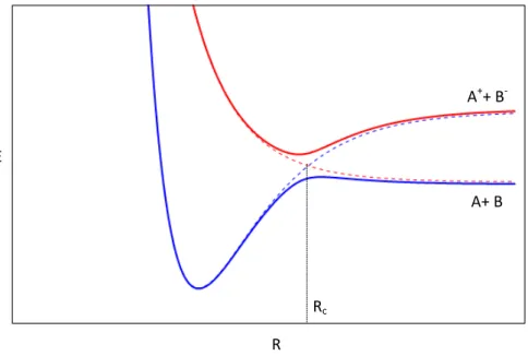
To better illustrate the ion-pair formation process from the charge transfer point of view, the analysis of the curve crossing is shown in figure 2.4.
R E
Rc
A++ B-
A+ B
Figure 2.4: Adiabatic and non-adiabatic potential energy curves for a general atom-atom collision, as a function of the internuclear distance (R). Full curves represent the adiabatic ionic (red) and covalent (blue) states. Dashed curves correspond to the non-adiabatic ionic (red) and covalent (blue) states. Adapted from [26].
It is clear from the curves representation that the non-adiabatic and adiabatic states are similar for internuclear distances much larger than the crossing radius, where an avoided crossing between the adiabatic states is observed. The separation between the covalent and ionic potentials at infinite A-B internuclear distance is given by the endoergicity value (equation 2.10).
covalent potential zero and the ionic potential can be given by a pure coulombic potential. Such consideration leads toRc being approximated by:
Rc = e 2
∆E =
14.41
IE(A)−EA(B) (2.15)
WithRcin Å and∆Ein eV.
Until now, in this discussion a single crossing point has been considered. How-ever, in an atom-atom collision, for a given impact parameterb <Rc, two crossing
points will appear. Considering a straight line trajectory, figure 2.5 illustrates the possible collision trajectories upon interaction.
Rc
b
A + B
A + B A+ + B–
A+ + B–
RC
“Ionic” path
“Covalent” path
Figure 2.5: Schematic of atom-atom scattering with b representing the impact parameter, the shaded area representing the repulsive part of the potential. Red curves represent the ionic path and blue curves represent the covalent trajectory. Adapted from [26].
2.2. DAMAGE BY ELECTRON TRANSFER
For ion-pair formation, the electron jump must occur only at the first or at the second crossing, which only happens within two of the four trajectories (inelastic scattering). If the electron transfer does not occur or if it occurs at both crossings, no ion-pair formation will happen (elastic scattering).
On a relevant note, to better understand the electron transfer process in atom-atom collisions, it is helpful to follow the potential curves illustrated in figure 2.4 together with the more pictorial representation of the process presented in figure 2.5. In fact, starting from the right of figure 2.4, one can simulate the neutral acceptor and electron donor atoms coming together (along the blue line) until they reach the first crossing point, where the electron can be transferred. The second crossing point is simulated following the curves from left to right.
2.2.3
Atom-Molecule Collisions
Although some of the principles discussed in section 2.2.2 still apply to atom-molecule collisions, to describe the latter system a much more elaborate analysis is required, due mainly to the increased structural complexity of the molecular target. New processes have to be considered when studying such a collision system, namely rotational, vibrational and electronic excitation of the electron acceptor (molecule), as well as collision-induced dissociation, or a combination of all the aforementioned processes.
The description of atom-molecule collisions is interpreted by means of multi-dimensional potential hypersurfaces, in which numerous nuclear coordinates of the molecule have to be taken into account, in contrast with the uni-dimensional po-tential energy curves derived from the collision between atoms. For interpretation purposes, the time period associated with rotational and vibrational movements of the molecule have to be considered in the analysis. The time it takes for a molecule to rotate is relatively long when compared with the collision time and therefore may be neglected, i.e. considered frozen. Nevertheless, the vibrational time is in the same order of magnitude of the collision time, meaning that vibrational effects have to be considered in the collision process [24].
Some models have been developed to electronically describe inelastic collisions between atoms and diatomic molecules [23]. However, such models are not valid for polyatomic molecules where, again, there is a significant number of processes that can occur. In fact, the mentioned models do not apply to the molecules studied throughout this thesis and therefore it is not convenient to make use of them.
electron transfer process in these collisional systems on a more qualitative per-spective. Indeed, by analysing and complementing the electron transfer data with electron scattering, quantum mechanical calculations and dissociative electron attachment profiles, it is possible to obtain relevant information about the general behaviour of such process.
As mentioned before, dissociative electron attachment consists of the capture of a free electron by the target molecule resulting in a TNI that may decay through different reaction pathways. Such mechanism may be compared with what occurs in atom-molecule collisions, bearing in mind two major differences: in the latter process the electron is initially in a "bound" state; and the capture of an electron will result in the formation of a positive ion species in the vicinity of the recently generated anionic molecular target. The aforementioned differences will influence the fragmentation pathways of the TNI when comparing DEA with electron transfer in atom-molecule collisions.
The electron transfer mechanism may be generically described as follows: on a first step, the "bound" electron is detached from the electron donor projectile; on a second step the electron is captured by the electron acceptor target molecule. From this rationale, one can state that electron capture from a molecule is a resonant process, much like for DEA, and thus only certain energy losses from the system can culminate in electron transfer. This means that if the available energy of the system is high enough for the anionic state of the molecule to be accessed, this state will be formed [27].
The available energy is defined as the kinetic energy of the electron donor in the centre-of-mass framework, considering its ionisation energy:
Ea = mtm
mtm+mK ·α·
Elab−IE (2.16)
With Ea being the available energy (in eV),mtm the target molecule’s mass, mK the projectile mass,Elab is the kinetic energy of the projectile relative to the
lab frame defined as the voltage applied to the potassium ion source, α is an
experimental correction factor and IE is the ionisation energy of the electron-donating projectile, which in the present experiment was neutral potassium atom. The potassium ionisation energy is 4.34 eV.
The experimental parameter (α) is adimensional (approximately 0.89) and
2.2. DAMAGE BY ELECTRON TRANSFER
assuming this formula appear to yield available energy values according to what is expected by DEA.
A resonant anionic state can be accessed if the available energy (Ea) of the
projectile is higher than the energy of such state. In contrast, anionic resonance states with energies above Ea cannot be accessed. Through this rationale, by
changing the kinetic energy of the potassium beam to values whereEais below
certain resonant anionic states, it has been shown for several molecules that the resonances accessed through electron transfer appear to be the same as in DEA, despite the fragments yield being different [27]. AlthoughEamay be higher than a
certain resonance, the electron is transferred with the energy equal to the accessed resonant anionic state.
As pointed before in this section, the presence of the electron donor in the vicinity of the resulting molecular anion has a critical influence on the reaction pathway after electron transfer. An example of the influence of this temporary reaction complex in the fragmentation channels pertains to the nitromethane (CH3NO2) studies. The parent anion (CH3NO−2) was observed in electron transfer
with potassium atoms measurements, whereas it was was not reported in DEA studies. Such difference is justified by the presence of the cationic potassium generated after transferring the electron, allowing enough time for the parent anion to stabilize into a stable geometry [29].
Despite this assumption, it is not totally clear the exact way the mentioned reaction works. The accepted empirical reasoning is that, after electron transfer, a chemical complex is formed that interacts through a coulombic potential. Such complex will probably suppress the rejection (autodetachment) of the extra elec-tron from the molecular anion. That is, the competition between autodetachment and formation of the parent anion favours the latter, in clear contrast with what happens in the DEA case.
autodetachment (section 2.1.1).
2.3
State Of The Art
As mentioned along the previous chapters, Sanche’s seminal studies [8, 11] show-ing that low energy electrons can efficiently damage DNA by inducshow-ing resonant single and double strand breaks, motivated field-related investigators to better understand electron driven reactions in the physiological medium. Indeed, several experimental and theoretical DEA studies with segments and building blocks of DNA and RNA molecules have been reported, in the gas-phase and deposited as thin films [2, 30, 31, 32, 33]. Investigation of electron attachment process to phosporic acid esters, in order to simulate the behaviour of the phosphate group in DNA [34], and to the nucleotide deoxycytidine monophosphate (dCMP) [35] are two good examples of DEA studies aiming to reveal the LEEs induced damage to DNA. Furthermore, formation of negative ions from electron attachment to other biological relevant molecules, such as amino acids, have been studied [36, 37, 38]. Site- and bond-selective cleavage upon DEA was reported for the nucleobases thymine an uracil [14, 17, 39], ribose [19], amino acids [40] and various other biomolecules. In the case of pyrimidine bases thymine and uracil, the loss of an hydrogen atom is site- and bond-selective from the N1 position of the ring for electrons with energies close to 1 eV, whereas electrons with energies between 1 eV and 3 eV are required to induce the loss of one hydrogen atom from the N3 position of the ring. These experiments revealed that electron-induced dissociation can be a controlled process, i.e. by tuning the initial electron energy one can control specific chemical reactions in DEA.
Aiming to better mimic electron driven reactions in the physiological medium, electron transfer in atom-molecule collision measurements were pursued. In fact, following the same path and reasoning taken for electron attachment experiments, research on electron transfer to pyrimidine nucleobases [41], sugar units present in the DNA and RNA chains (D-ribose and an analogue THF) [42, 43], amino acids valine and alanine [44], and other biomolecules was performed. Remarkable site and bond selectivity has also been shown [41] in thymine and uracil studies: by tuning the collision energy of the projectile potassium beam, H− abstraction
results from N-H bonds rather than from C-H ones, and from N1 site versus N3. A joint study has also revealed the structure NCO−as a key fragment upon
2.3. STATE OF THE ART
proposed both site selectivity and a chain of reactions composing a slow decay process as possible causes underlying the formation of the referred anion.
Chemoradiation therapy is gradually becoming a dominant cancer treatment. When using both chemotherapy simultaneously with radiotherapy, lower doses are required compared to single radiotherapy treatments. Such concomitant ther-apy involves a radiosensitizer that will improve DNA damage upon radiation interaction, increasing cancer cells death rate. Halouracils are a good example of radiosensitizers. Such molecules are uracil analogues where the methyl group in the position C5 is replaced by an halogen atom. Electron transfer studies to halouracils (5-chlorouracil and 5-fluorouracil) yielded several anionic fragments that require the ring to break, resulting in its function loss,proving its enhanced "sensitivity" to radiation damage [46].
The role of sulphur atoms in electron driven reactions to biological molecules still need to be unravelled. Naturally sulphur containing amino acids, such as cysteine and methionine, have already been subjected to DEA studies [47, 48]. On a recently published article [49], the authors show results of DEA to gas-phase thiothymine, which is a sulphur containing analogue of thymine, and suggest that the sulphur atom plays a key role on the dissociation process. Making use of experimental data and theoretical computational methods, they were able to conclude that the sulphur atom within this molecule strongly controls the fragmentation pathways. The most intense products of the dissociation process comprise the sulphur atom (S−, SCN− and[M−S]−, where M represents the
intact molecule), suggesting that the resonances are localized in the C-S group. In the same line of thought, electron attachment to sulphur containing analogue of uracil (2-thiouracil) revealed that most of the damage is localised at the sulphur site, the main yielded fragment being the thiocyanate,SCN−[50].
These results show that certain reactions can be controlled by placing a sulphur atom at a specific site within nucleobases. Hence, they represent a first step to understand the sulphur containing molecules role on further inducing cellular damage and its potential application in chemoradiation therapy.
The work performed in this thesis comprises measurements with two sulphur containing molecular targets: taurine (2-amino-ethanesulfonic acid) and thiapro-line (L-4-thiazolidinecarboxylic acid).
functions: taurine promotes bile flow and increases bile acid production; in the central nervous system taurine has the role of neurotransmitter and acts as neuro-protective agent; it has positive cardiovascular antiarrhythmic effects; and its deficiency leads to retinal degeneration. Furthermore, taurine has therapeutic applications. In fact, it may inhibit nerve stimulation and has been reported to control motor tics, such as uncontrollable facial twitches [52], and it has been suggested that taurine may act as an antioxidant.
Chapter 3
Experimental Set-ups
This chapter is devoted to the characterization of the two experimental set-ups used throughout the work performed in this thesis. The bulk of the work pertains to the studies on electron transfer in collisions between neutral potassium atoms and biomolecules, and was performed in Atomic and Molecular Collisions Lab-oratory, CEFITEC. The crossed beam set-up designed to perform such studies is described in the first section.
Part of the research studies were performed in the Department of Chemistry of Siedlce University in Poland, where dissociative electron attachment mea-surements were conducted, making use of an electron-molecule crossed beam apparatus described in the second section of the present chapter.
3.1
Electron Transfer Experimental Set-up
3.1.1
Apparatus Overview
A scheme of the experimental device is presented in figure 3.1. The apparatus can be divided into two main regions, which are set in two high vacuum chambers differentially pumped through diffusion pumps, reaching base pressures of the order of 10−5Pa (10−7mbar). The chambers communicate through an aperture
valve.
to the potassium beam, is created in an oven (called molecular target oven) where liquid, gas and solid samples are admitted. Both beams enter the collision region through two different collimation slits: an horizontal 5×0.5 mm slit is placed in
the potassium beam path, whereas an aperture with 1 mm diameter is placed in the molecular beam axis.
In addition to the molecular target oven and the Langmuir-Taylor detector, the second region comprises the extraction system of the TOF mass spectrometer. The collision region consists of two parallel plates 1.2 cm apart and equally distanced to the collision plane. The anionic fragments resulting from electron transfer in potassium-molecule collisions are extracted by applying an electric field normal to the collision plane. The fragments pass through an Einzel lens system designed to focus the ions before entering the time-of-flight tube towards the channeltron detector.
In the second chamber a set of heating lamps is installed to both avoid the condensation of samples on the chamber’s walls and to facilitate the baking of the chamber. Typical working pressures are in order of 6×10⁻⁴Pa (6×10⁻⁶mbar),
depending on the sample. Both the TOF tube and the liquid and gas samples inlet system tubes are wrapped with heating bands to avoid condensation of the samples on the respective walls.
3.1.2
Projectile Beam
The accelerated neutral potassium beam is obtained through a process based on the collision between a hyperthermal potassium ion (K+hyper) and a thermal potassium
atom (Kther0 ), resulting in an electron jump from the second to the first, i.e. they
undergo resonant charge exchange. Being a resonant process, the hyperthermal potassium ion becomes neutral and no kinetic energy is lost. Such process can be described as follows:
K+hyper+K0ther →K0hyper+K+ther (3.1)
Where the products of the reaction are the desired hyperthermal potassium atom (K0hyper) and the thermal potassium ion (K+ther).
3.1. ELECTRON TRANSFER EXPERIMENTAL SET-UP
TOF
PO
CEC DP LTD
MTO
CPS
Figure 3.1: Schematic of the electron transfer experimental device. PO: Potassium oven, CEC: Charge exchange chamber, CPS: Cationic potassium source, DP: De-flecting plates, LTD: Langmuir-Taylor detector, MTO: Molecular target oven, TOF: TOF mass spectrometer. Adapted from [26].
oven is maintained 20 K higher than the potassium oven to avoid condensation inside and in the entrance and exit collimation slits.
The potassium ions are pushed towards the charge exchange oven with the desired energy by applying an acceleration voltage between the ion source and the oven, where the neutral potassium lies. The ions that enter the oven go through resonant charge exchange and become neutral (K0hyper).
The resulting beam is composed mainly of hyperthermal potassium atoms that enter the collision chamber with a kinetic energy given by the applied acceleration voltage. However, since only a fraction of the potassium ions undergo resonant charge exchange, exiting the charge exchange oven one finds hyperthermal potas-sium ions (K+hyper), which therefore must be removed. With that purpose, a pair of
plates. Such current also gives an indication of the charge exchange efficiency, which is related to the potassium vapour density in the charge exchange oven. The voltage applied to the deflecting plate varies according to the beam kinetic energy (optimal values were tested [26]). The measured ion currents increase with increasing beam kinetic energies and are in the order of 1-100 nA.
0
T her
K
0
Hyper Hyper
K + K+ KHyper+
0
Hyper
K
K Oven
Ion Source
Deflecting plates
Charge Exchange Oven
Figure 3.2: Charge exchange system schematics. Taken from [26]
3.1.3
Langmuir-Taylor Surface Detector
The Langmuir-Taylor detector (figure 3.3) is placed at the entrance of the collision chamber in order to monitor the potassium neutral beam that reaches this point. It consists of a stainless steel cylindrical collector placed around a high purity (> 99%) iridium filament. The collector has two holes along the beam axis and
the filament is placed above the main section of the beam, in order to minimize interfering with it.
3.1. ELECTRON TRANSFER EXPERIMENTAL SET-UP
the hyperthermal potassium atoms beam intensity. A typical current of 0.63 A is applied to heat the filament, whereas +60 V are applied in order to repel the ionized potassium.
Figure 3.3: Langmuir-Taylor detector.
3.1.4
Molecular Target Oven
The molecular target oven (figure 3.4) is composed of a copper outer body, a removable stainless steel sample holder that fits into the outer body through a back opening, and a copper capillary tip. The outer body is also connected to a liquid and gas sample admission system.
The oven is heated through a halogen bulb and surrounded by a stainless steel reflector to increase the bulb’s heating efficiency. The bulb’s intensity is controlled by a variac and the outer body temperature is monitored by a K-type thermocouple.
The oven is set on a platform allowing for a fine alignment with the collision center.
3.1.5
Time-of-Flight Mass Spectrometer
3.1.5.1 Working Principle
The time-of-flight mass spectrometer is founded on the simple principle that charged particles with different mass-to-charge ratios (m/z), when subjected to
the same force, obtain different velocities and thus will take different flight times along a fixed field-free region.
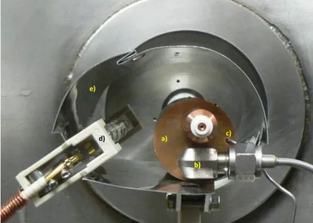
a)
b) b)
c)
d)
e)
Figure 3.4: Picture of the molecular target oven. a) Molecular target oven - outer body; b) Gas and liquid samples inlet system; c) Thermocouple; d) Heating lamp; e) Radiation deflector. Adapted from [56].
to the extraction plate, setting an electric field between the plate and the drift region. The extracted ions cross the drift region with velocities that are inversely proportional to the square root of their masses. This means that heavier, hence slower, ions will arrive at the detector after the lighter ions with higher velocities.
Depending on the drift region length and the extraction potential applied, ion flight times fall in the range of 10 to 200 µs. Such fact represents a significant
advantage of TOF devices in comparison to other types of mass spectrometers, since a complete mass spectrum is obtained within several tens of microseconds.
Drift Region Extraction Region
-V
D
et
ec
to
r
3.1. ELECTRON TRANSFER EXPERIMENTAL SET-UP
3.1.5.2 Implemented TOF
There have been several improvements to the simple design described above, such as reflectron type TOF spectrometers, with the intent to increase the mass resolution of the spectrometer. Within the scope of the research work carried out in Lisbon, the configuration used is a dual-stage time-of-flight system (Wiley-McLaren geometry [57]). The main upgrade of this geometry from the single-stage one is the introduction of a second extraction region, called acceleration region, that allows longer field-free regions maintaining the possibility to rectify the flight time of ions with the same mass created at different initial positions. Both the flight time and space-focusing are two of the most significant parameters regarding mass resolution.
The TOF mass spectrometer used, pictorially presented in figure 3.6, consists of an extraction region (which corresponds to the collision region), an acceleration region, an einzel lens system, a set of deflecting plates, a field-free drift tube and a channeltron detector.
Extraction System
EL DP
Drift Tube Detector
AR ER
1
st
G
rid
2
n
d
G
rid
R
P
Figure 3.6: Schematic of the implemented TOF mass spectrometer. RP: Repeller plate; ER: Extraction Region; AR: Acceleration region; EL: Einzel lens system; DP: Deflecting plates. Adapted from[26].
Extraction and Acceleration Regions
The extraction region is where the neutral potassium and molecular beam collide. It consists of two electrodes (repeller plate and first grid) 1.2 cm apart. Before reaching the collision region both beams are made to pass collimating slits to avoid saturation.
repeller plate consisting of a -350 V pulse added to a -3500 V constant value, causing the negative ions to leave this region into the acceleration region.
Ions entering this region suffer a significant acceleration due to the -3500 V constantly applied to the first grid with respect to the second grid referenced to the ground, causing them to enter the einzel lens region and ultimately the drift region and detector. When the -350 V pulse is active, the particles will leave the extraction system with a total energy of 3850 eV. Whereas when the pulse is not active, the voltage difference between the repeller plate and the first grid is zero, and the particles are not extracted. Thus, this pulsed signal is used as a start signal for the time-of-flight measurements.
Einzel Lens System
The purpose of the einzel lens system is to concentrate and converge the ions extracted from the collision region to the channeltron detector, optimizing the detection and the yielded signal. This set works like an optical lens system, forcing the ions to converge to a focal point without changing its energy. It comprises three aligned cylinders, where a voltage is applied to the central one and the others are grounded. Several tests upon the apparatus assembling allowed to conclude that the optimal voltage to apply is -1500 V. With the same purpose, a set of deflecting plates were also assembled after the einzel lens system. However, the deflecting plates are grounded since they were found to be irrelevant to the signal improvement.
The voltages applied to the extraction system are summarized in figure 3.7.
-3500V + -350V
-3500V -1500V
Figure 3.7: Voltages applied to TOF extraction system. Adapted from[26].
Channeltron Detector
3.1. ELECTRON TRANSFER EXPERIMENTAL SET-UP
emits secondary electrons. Due to a voltage drop of about 2000 V between the entrance and the rear end of the detector, the electrons collide once again with the channeltron’s walls, generating a cascade of electrons. As such, for each ion impact, the detector generates a negative voltage pulse with 20 ns duration and an amplitude of typically -20 mV.
TOF Mass Spectra
Once in the field-free region, ions with different masses will reach the detector at different time intervals. Since the time of flight is proportional to the square root of (m/z) and that all fragments have the same charge (-e), the resulting spectrum
assigns to every channel a given mass. Each channel corresponds to a 8 ns time window. The time-of-flight starts from the moment the extraction pulse is applied.
3.1.6
Vacuum System
The vacuum system comprises two chambers (potassium chamber and collision chamber) differentially pumped.
The vacuum conditions in the potassium chamber are guaranteed by a diffusion pump and a liquid nitrogen trap to avoid migrations of diffusion pump oil into the chamber. The diffusion pump backup is guaranteed by a two-stage rotatory pump with a magnetic valve and a sieve trap in between to prevent the contamination with rotatory oil vapours.
The vacuum conditions in the collision chamber chamber are guaranteed in a similar way as the one described in the potassium chamber case. The high-vacuum is achieved by a diffusion pump. The TOF system is pumped differentially by a turbomolecular pump placed near the channeltron detector. Both the turbo and the diffusion pumps are backed up by a two-stage rotatory pump. The liquid and gas sample inlet system is also differentially pumped by a two-stage rotatory pump.
Both chambers are connected through a manual gate valve that allows an independent chamber operation. Therefore, it is possible to operate one of them at atmospheric pressures keeping the other in high-vacuum conditions, which is important when cleaning the collision chamber or potassium replacement is needed.
The rotatory pumps provide an ultimate pressure of 1 Pa. Only after primary vacuum pressures are reached the pumping is changed to the diffusion and tur-bomolecular pumps, which provide high-vacuum pressures, in the order of 10−5
It is relevant to stress the importance of achieving vacuum in the conditions described, since it is related to mean free path, i.e. the average distance that a particle travels between collisions. The mean free path is given by:
λ∼= 7×10
−3
WorkingPressure(cm) (3.2)
Considering that during measurements the base pressure is around 6×10⁻⁵
Pa, the mean free path is approximately 116 m. Given that the distance between the plane where the potassium ions are generated and the collision region is about 50 cm, it is fair to state that the measurements are performed under single-collision conditions.
3.2
Dissociative Electron Attachment Experimental
Set-up
3.2.1
Apparatus Overview
Free electrons are made to collide with a molecular target by means of a crossed beam arrangement as shown in figure 3.8, where negative ions resulting from dissociative electron attachment are detected.
The apparatus consists of one high-vacuum chamber. An electron beam with well-defined energy is generated by a trochoidal electron monochromator (TEM) and focused into the reaction region. Two halogen bulbs heat the chamber with two purposes: (1) to sublimate the solid samples generating an effusive molecular target beam, and (2) to prevent condensation of the sample in the lens system and walls of the chamber. The temperature inside the chamber is controlled by a PT100 resistor. The sublimated molecular beam is guided through a capillary towards the collision region. Negative ions formed from the electron-molecule collision are mass analysed by a quadrupole mass spectrometer (QMS) and detected by a secondary electron multiplier (SEM).
3.2. DISSOCIATIVE ELECTRON ATTACHMENT EXPERIMENTAL SET-UP
Gas and liquid samples with high vapour pressure are admitted into the chamber through a gas-inlet system (Swagelok) with a leak valve incorporated. The system is also equipped with aSF6gas cylinder, allowing for energy calibration
with the known resonance spectrum for this compound, as described in subsection 3.2.4. Further details can be found elsewhere [9, 58]
QMS SEM
IO E
B
ES
TEM
C1/C2
MTO B1-B3
S1-S4
RA
Figure 3.8: Schematic of the dissociative electron attachment experimental de-vice. ES: Electron source, B1−B3: Focusing lenses with non-axial holes, TEM:
Trochoidal electron monochromator,S1−S4: Focusing lenses with axial holes, RA:
Reaction area, MTO: Molecular target oven, IO: ion optics, QMS: Quadrupole mass spectrometer, SEM: Secondary electron multiplier, −→E: Electric field (y-direction), −→
B: Magnetic field (x-direction).
3.2.2
Monoenergetic Electron Beam
The electrons are emitted from a hot tungsten filament supplied with a current of approximately 2.3 A. A set of three electrodes with non-axial holes following the filament (B1-B3) focuses the electrons into the deflection region, where the energy
![Figure 2.1: Thermalization of electrons after being created by interaction of high energy quanta with the physiological medium: energy, time and space scales [1]](https://thumb-eu.123doks.com/thumbv2/123dok_br/16547877.737026/24.892.239.603.164.452/figure-thermalization-electrons-created-interaction-energy-quanta-physiological.webp)


![Figure 3.2: Charge exchange system schematics. Taken from [26]](https://thumb-eu.123doks.com/thumbv2/123dok_br/16547877.737026/44.892.135.729.287.629/figure-charge-exchange-system-schematics-taken-from.webp)