Reactive electron scattering from
biomolecules and technologically relevant
molecules
Carolina Raquel Guedes Matias, MSc.
A thesis submitted to the University of Innsbruck and Universidade Nova de Lisboa for the degree of Philosophy Doctor (PhD) in Physics
Supervisor: Assoz. Prof. Dr. Stephan Denifl Co-supervisor: Prof. Dr. Paulo Limão-Vieira
Innsbruck
i
I would like to thank my supervisors, Professor Stephan Denifl and Professor Paulo Limão-Vieira for not only giving me the opportunity to perform my PhD thesis under their supervision, but also for their support, dedication and orientation. They were always available to help me in anything I needed.
To Professor Paul Scheier for accepting me in his working group and for all advises, which certainly made a difference in my training.
To all my colleagues at the Institute for Ion Physics and Applied Physics, University of Innsbruck, for making my stay as comfortable as possible, for the welcoming atmosphere and all support over these years. Especially to David and Josi who always had an answer to my questions. Every day they would provide some minutes of their busy time to help, discuss and advise me. I would also like to make a special thanks to my colleagues and friends, Marcelo and Andi, for the great time we have had together in the research activities as well as for all the support given when I most needed it.
To all my friends who always had a word of support and motivation. They helped me to successfully overcome some difficult times in this past three years.
To my parents for their unconditional support, for their trust and for the opportunities that they provided me over these years. Without their support I would not have been able to come so far.
To my little brother that although I don’t say it too loud, I care about him very much.
iii
Abstract
The role of a set of gases relevant within the context of biomolecules and technologically relevant molecules under the interaction of low-energy electrons was studied in an effort to contribute to the understanding of the underlying processes yielding negative ion formation. The results are relevant within the context of damage to living material exposed to energetic radiation, to the role of dopants in the ion-molecule chemistry processes, to Electron Beam Induced Deposition (EBID) and Ion Beam Induced Deposition (IBID) techniques. The research described in this thesis addresses dissociative electron attachment (DEA) and electron transfer studies involving experimental setups from the University of Innsbruck, Austria and Universidade Nova de Lisboa, Portugal, respectively.
This thesis presents DEA studies, obtained by a double focusing mass spectrometer, of dimethyl disulphide (C2H6S2), two isomers, enflurane and isoflurane (C3F5Cl5) and two
chlorinated ethanes, pentachloroethane (C2HCl5) and hexachloroethane (C2Cl6), along with
quantum chemical calculations providing information on the molecular orbitals as well as thermochemical thresholds of anion formation for enflurane, isoflurane, pentachloroethane and hexachloroethane. The experiments represent the most accurate DEA studies to these molecules, with significant differences from previous work reported in the literature. As far as electron transfer studies are concerned, negative ion formation in collisions of neutral potassium atoms with N1 and N3 methylated pyrimidine molecules were obtained by time-of-flight mass spectrometry (TOF). The results obtained allowed to propose concerted mechanisms for site and bond selective excision of bonds.
v
Symbols and acronyms
1-MeT 1-methyl-thymine
1-MeU 1-methyl-uracil
1p One particle resonance
2p-1h Two particle-one hole resonance
3-MeT 3-methyl-thymine
3-MeU 3-methyl-uracil
a. m. u. Atomic mass unit
a.u. Arbitrary unit
AD Autodetachment
AE Appearance energy
B Magnetic field
BOA Born-Oppenheimer approximation
D Bond dissociation energy
DBS Dipole-bound state
DD Dipolar dissociation
DEA Dissociative electron attachment
DMDS Dimethyl disulphide
DNA Deoxyribonucleic acid
DSB Double strand break
vi e. g. for example
EA Electron affinity
EAad Adiabatic electron affinity
EAv Vertical electron affinity
EI Electron ionisation
Ek Kinectic energy
ESA Electrostatic analyser
et al. and others
eV electron-volt
FCF Franck-Condon factor
FWHM Full width at half maximum
h Plank constant, 6.626×10⁻³⁴ J.s-1
ħ Reduced Plank constant, 6.6×10⁻¹⁶eV/s (h/2π)
HOMO Highest occupied molecular orbital
i.e. in other words (id est)
IE Ionisation energy
IMS Ion mobility spectrometry
K Potassium
Khyper Hyperthermal potassium atom
Kther Thermal potassium atom
kV kilovolt (103 V)
vii LEE Low energy electron
LUMO Lowest unoccupied molecular orbital
M Molecule
M* Excited molecule
m* Apparent mass
m/z Mass to charge ratio
m1 Molecular fragment
MeV Mega electron-volt (106 eV)
MIKE Mass analysed ion kinetic energy
MO Molecular orbitals
MS Mass spectrometry
NDA Non dissociative attachment
R Nuclear coordinates
Rc1 First crossing radius
Rc2 Second crossing radius
s Second
SSB Single strand break
T Thymine
Th Thomson (mass unit)
TNI Temporary negative ion
TNT Trinitrotoluene
viii U0 Initial kinetic energy
Va Attractive polarization interaction
VDE Vertical detachment energy
VE Vertical excitation
VEA Vertical electron attachment
Veff Effective potential
VG-ZAB Double focusing mass spectrometer
Vl Repulsive centrifugal potential
Γ Resonance width
ΔH°f Heat of formation
ν Vibrational level
σ* σ antibonding orbital
τ Autodetachment lifetime
ix
List of Figures
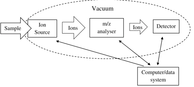
Figure 1.1 – Schematics of the various components present in a mass spectrometer. Represented are: the sample inlet; ion source; m/z analyser (separates the ions according to their individual m/z values); detector (generates a signal whenever an ion reaches the detector); vacuum system (provides binary collision conditions); computer (drives each of
the spectrometer’s component, records and stores the data obtained). Adapted from [4]. .. 2
Figure 2.1 - Schematic representation of direct electron scattering. Adapted from [1]. ... 6
Figure 2.2 - Schematic representation of resonant electron scattering. Adapted from [1]. . 6
Figure 2.3 - Born-Oppenheimer potential energy curves for a molecule in the ground state (M) and its electronically excited state (M–). Vertical transitions are shown
representatively. Also represented are the vibrational modes (ν) and the Franck-Codon region (shadow). Adapted from [3]. ... 8
Figure 2.4 - Dynamics of Autodetachment (AD) and dissociative attachment (DEA) in electron-molecule scattering through resonances. 𝜈 represents a vibrational quantum number. Adapted from [8]. ... 11
Figure 2.5 - Schematics of a potential curve for low energy electron interactions with a molecule ABC. Representation of possible decay processes: DEA (dissociative electron attachment), AD (autodetachment) and NDA (non-dissociative electron attachment). Adapted from [6]... 12
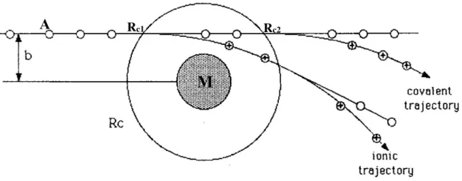
Figure 2.6 – Representation of the collision trajectories between an alkaline atom (A) and a molecule (M). The crossing radius corresponds to the external circle and the repulsive potential region is represented by the dashed area. When the electron is transferred at Rc1
the trajectory is known as ionic, whereas at Rc2 the trajectory is termed covalent. Adapted
from [14,17]. ... 15
Figure 2.7 - Schematic diagrams of potential energies. Representation of the electron affinity (EA), vertical detachment energy (VDE) and vertical attachment energy (VAE). Adapt from [6]. ... 16
x
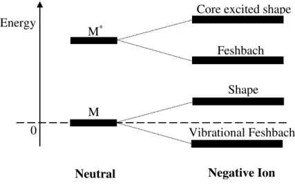
Figure 2.9 - Classification of the different types of resonance according to their energy in comparison to the neutral parent (M). Adapted from [1]. ... 18
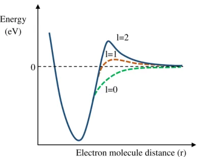
Figure 2.10 - Representation of the effective potential of the electron-molecule interactions depending on their distance (r). Depending on the angular momentum, different potential
barriers are formed. For l = 0, no potential barrier is formed, while for l ≠ 0 a centrifugal
barrier is created and the electron can be momentarily trapped inside the effective potential. Adapted from [21]... 19
Figure 2.11 – Representation of a dipole bound state or also called vibrational Feshbach resonance, since its vibrational levels are below the corresponding levels of the neutral. Adapted from [25]... 20
Figure 2.12 – Scheme of a potential energy diagram where the neutral ground state and electronically excited state of molecule AB is visible. Core exited shape and Feshbach resonances are also represented. Adapted from [21]. ... 21
Figure 3.1 – Schematics of the double focusing spectrometer used to perform DEA experiments [1]. ... 25
Figure 3.2 – a) Picture of the VG-ZAB ion source chamber and gas and liquid inlets. A heating band and aluminium foil is wrapped around the liquid inlet. b) Detailed view of the ion source and capillary. ... 26
Figure 3.3 - Schematics of the ion block. Adapted from [4]. ... 28
Figure 3.4 - Production of secondary electrons in a channel electron multiplier. The output will be amplified and discriminated by a preamplifier discriminator unit which will trigger a counter. This signal will be processed by a computer. Adapted from [5,6]. ... 32
Figure 3.5 – Negative ion formation of SF6–, SF5–, F–and F2– from the collision of electrons
with SF6. The energies used to calibrate energy spectra are identified in the graph. Adapted
from [12]. ... 35
Figure 3.6 - Photograph of the experimental set-up used to perform electron transfer experiments. ... 36
Figure 3.7 - Schematics of the charge transfer set-up. Adapted from [13]. ... 37
Figure 3.8 – Schematics of the charge exchange beam formation. Adapted from [13]. ... 38
xi
Figure 3.10 - Generic schematics of a time-of-flight mass spectrometer. ... 42
Figure 4.1 – Time-scale schematic of radiation exposure on biological systems. From [7]. ... 48
Figure 4.2 - Schematics of a single and a double strand break. ... 48
Figure 4.3 –a) schematic drawing of a thymine molecule with atom labelling numbers (in red). b) and c) represents the possible N-methylated sites of thymine, 3-methylthymine and 1-methylthymine, respectively. ... 49
Figure 4.4 – a) schematic drawing of a uracil molecule with atom labelling numbers (in red). Uracil replaces thymine in the transcription of DNA and is also present in the RNA. b) and c) represents the possible N-methylated sites of uracil, 3-methyluracil and 1-methyluracil, respectively. ... 49
Figure 4.5 - Schematic representation of NCO– path formation when a hydrogen atom is
removed from position N1. Further reaction steps occur upon the loss of NCO– (see publication below). ... 51
Figure 4.6 – Schematic representation of the different NCO– path formation when a hydrogen atom is removed from position N3. Further reaction steps occur upon the loss of NCO– (see publication below). ... 52
Figure 4.7 - Schematic drawing of a dimethyl disulphide. From [28]. ... 64
Figure 4.8 - Schematic drawing of an example of IMS. a) Principle of operation and b) the flow of gas inside an IMS apparatus. From [49]. ... 75
Figure 4.9 - Schematic drawing of isoflurane a) and enflurane b). These two molecules are structural isomers. The position of two fluorine atoms are swapped with a chlorine and a hydrogen atoms, as pointed out in the figure. Adapted from [53,54]. ... 77
Figure 4.10 – Schematic drawing of the chlorinated ethanes: hexachloroethane a) and pentachloroethane b) used to perform DEA experiments. From [56,57]. ... 78
Figure 4.11 - Schematic illustration of the EBID and IBID techniques. In EBID an electron beam used, while IBID uses an ion beam. Irradiation by high energy electrons and ions lead to metallic structures from adsorbed organometallic molecules on the surface of a solid substrate. Adapted from [63]. ... 102
xii
xiii
List of Tables
Table 3.1 – Specifications of the system. ... 43
xv
Table of contents
Acknowledgments... i
Abstract ... iii
Symbols and acronyms ... v
List of Figures ... ix
List of Tables ... xiii
Table of contents ... xv
1. Motivation ... 1
2. Electron Induced Processes ... 5
2.1. Scattering processes ... 5
2.1.1. Direct elastic scattering ... 5
2.1.2. Direct inelastic scattering ... 6
2.1.3. Resonant scattering ... 6
2.2. Born-Oppenheimer-Approximation ... 7
2.3. The Franck-Condon principle ... 9
2.4. Negative ion formation through electron attachment ... 9
2.4.1. Dissociative electron attachment ... 10
2.4.2. Dipolar dissociation ... 13
2.4.3. Electron transfer ... 13
2.4.4. Electron affinity ... 15
2.4.5. One particle and two particle-one hole resonances ... 17
2.4.6. Metastable ions ... 22
xvi
3.1. Apparatus used to perform DEA experiments ... 25
3.1.1. Introducing a sample in the chamber ... 26
3.1.1.1. Gas phase sample ... 26
3.1.1.2. Liquid phase sample ... 27
3.1.1.3. Solid phase sample ... 27
3.1.2. Ion source ... 28
3.1.3. Mass analysis of ions ... 29
3.1.4. The Electrostatic Analyser and Magnet Combination ... 30
3.1.5. Detection: Channeltron ... 31
3.1.6. Mass resolution ... 32
3.1.7. Measurements ... 32
3.1.8. Calibration... 34
3.2. Apparatus used to study electron transfer ... 36
3.2.1. Introducing the samples ... 37
3.2.2. Production of the neutral potassium beam and ions ... 38
3.2.3. Time of flight spectrometer ... 39
4. Results and discussion ... 46
4.1. Biomolecules ... 46
4.1.1. Comparative studies upon potassium and electron collisions with biomolecules: site selectivity ... 47
4.1.2. Dissociative electron attachment to dimethyl disulphide ... 64
xvii
4.2.1. Dissociative electron attachment to enflurane, isoflurane and chlorinated
ethanes (pentachloroethane and hexachloroethane) ... 75
4.2.2. Low-energy electron interaction with tungsten hexacarbonyl ... 102
5. Conclusions and further work... 116
5.1. Biomolecules ... 116
5.1.1. Comparative studies of potassium and electron collisions with biomolecules: site selectivity ... 116
5.1.2. Dissociative electron attachment to dimethyl disulphide ... 118
5.2. Technologically relevant molecules ... 118
5.2.1. Dissociative electron attachment to volatile anaesthetics (enflurane, isoflurane) and chlorinated ethanes (pentachloroethane and hexachloroethane) ... 118
5.2.2. Low-energy electron interaction with tungsten hexacarbonyl ... 120
Appendix I: List of other published papers... 122
1
1.
Motivation
he study of the behaviour of charged particle beams with atoms and molecules is among the most significant developments in physics [1] with several applications in science and technology. In the universe, ionised particles are one of the most abundant species, however, in the Earth’s environment, and generally speaking, the matter consists mostly of neutral atoms and molecules in different stages of aggregation. Nevertheless under certain conditions ionised atoms and molecules can be created. These conditions are time and space dependent and can vary from a simple lightning striking the Earth to complex devices in science and technology that use techniques with charged particles as a mean of probing a particular target [2].
The question that can be raised now is: Why is then the study of charged particle interactions with atoms and molecules so significant [2]? The answer certainly depends on the particular area of study and the approach needed. The study of charged particles is not only important in physics, but in medicine, chemistry, pharmacy, and many others, so the key issue is to understand and get detailed knowledge on the underlying mechanisms probed by such interactions. However, there is something in common to all fields that use ionised particles: i) ions can be easily controlled by electric and/or magnetic fields and ii) they can be rather easily detected [2]. Using ions as a probing tool, also allows having an insight into the very fundamental aspects of the target behaviour [1,2]. From a fundamental point of view the understanding of the electronic structure of atoms and molecules and their chemical reactivity is of great importance in several scientific and technological areas, as pointed out before. Molecules present in the interstellar medium (e.g. C60, CH4), in the
Earth’s lower atmosphere (N2, O2), those linked with environmental issues as global
warming and ozone depletion (e.g.: anthropogenic emissions), explosives and narcotics and molecules of biological interest (e.g.: H2O, deoxyribonucleic acid bases and essential
amino acids) are some examples of relevant species that play a significant role in our daily lives. Therefore a comprehensive knowledge of how these species behave may result in development of new tools and technologies which may certainly affect our lives.
Mass spectrometry has been largely used as a probing technique for atoms and molecules. This is an important tool in many fields of science and technology and was used in the present work to identify the species formed after the interaction of electrons and
2
atoms with bare molecules. Briefly, in this technique a neutral gas sample is made to interact with a beam of electrons (either for attachment or ionisation), and the charged particles formed (either positive or negative) are separated according to their mass to charge ratio (m/z) and detected [3] (see Figure 1.1). However not all samples are gaseous. Solid and liquid samples can be transferred into the vacuum systems via a proper sample inlet system which in some cases can be heated in order to increase the samples’ vapour pressures [3]. In an ion source chamber, for pressures in the range of 10-5– 10-6 mbar (~10 -3 – 10-4 Pa) the mean free path for the ions is long enough, meaning that bimolecular
interactions are almost impossible [3].
Figure 1.1 – Schematics of the various components present in a mass spectrometer. Represented are: the sample inlet; ion source; m/z analyser (separates the ions according to their individual m/z values); detector (generates a signal whenever an ion reaches the detector); vacuum system (provides
binary collision conditions); computer (drives each of the spectrometer’s component, records and stores the data obtained). Adapted from [4].
The interaction of low energy electrons with neutral molecules and/or atoms can produce negatively charged ions, which are dependent on the energy of the incoming electron, whereas positively charged ions can be formed as long as the incoming electron has an energy equal or greater than the ionisation energy (typically for molecules such threshold is >10eV) [2]. The formation of cations or anions by electron interactions with atoms and/or molecules allows to obtain information on their atomic and/or molecular states as it happens in electron scattering processes. Using different experimental methods
Vacuum
Ion Source
m/z analyser
Ions Ions Detector
3
it is possible to obtain very precise information about energy and angular distribution of the scattered particles, radiation emitted, fragments produced, etc. [1,3]. The studies performed within this thesis made use of mass spectrometry to allow obtaining information about the fragmentation pathways of selected ions. The experimental data obtained in these studies can also help benchmarking theoretical calculations and find out better parameters for complex simulations, which will then help to better understand the whole chemical-physical reaction processes behind the electron/atom interaction with a particular target molecule.
4
References
[1] N.F. Mott, H.S.W. Massey, The Theory of Atomic Collisions, Oxford University Press, Great Britain, 1949.
[2] E. Illenberger, J. Momigny, Gaseous Molecular Ions. An Introduction to Elementary Processes Induced by Ionization, Steinkopff/Springer, New York, 1992.
[3] J.H. Gross, Mass Spectrometry, Springer Verlag, Germany, 2004.
5
2.
Electron Induced Processes
he following chapter is an overview of the important processes and mechanisms for the discussion of the results presented in this thesis. The interaction of electrons with molecules is the main focus of the current thesis, however electron transfer experiments have also been performed. Collisions between fast neutral atoms and molecules will be briefly presented. From the interaction of an electron with a molecule, electron attachment is one of the possible processes attained and so studied here. In the case of atom-molecule collisions, an electron donor atom (in the case of this thesis, neutral potassium) transfers an electron to the target molecule in a process well-known as electron transfer. Before going into detail about negative ion formation, some introductory notions are presented in the next sections.
2.1.
Scattering processes
The interaction of an electron with a molecule is a process that can be divided into two classes: direct (Figure 2.1) and resonant scattering (Figure 2.2). Direct scattering is characterized by the collision of an electron with the target molecule with the electron being scattered after the interaction [1]. If the total kinetic energy of the system (electron + molecule) is conserved, the process is known as elastic scattering, whereas if the total kinetic energy of the system is not conserved is named inelastic scattering. Direct electron scattering is a non-resonant process, it means that the incident electron may transfer an
amount of its kinetic energy to the molecular target.
2.1.1. Direct elastic scattering
In a first approximation, during an elastic scattering the incident electron energy does not change, i.e., there is a total conservation of the kinetic energy (Δ𝐸𝑘~0). No energy
6
molecular bonds will occur. However, the electron will be deviated from its original trajectory.
𝐴𝐵𝐶 + 𝑒−(𝐸
1) → 𝐴𝐵𝐶 + 𝑒−(𝐸2) 𝐸1 ≈ 𝐸2 2.1
Figure 2.1 - Schematic representation of direct electron scattering. Adapted from [1].
2.1.2. Direct inelastic scattering
In contrast with the elastic scattering, in an inelastic scattering there is no conservation of the kinetic energy (Δ𝐸𝑘 ≠ 0). The electron loses some kinetic energy that will be transferred to internal excitations of the molecule (electronic, vibrational and rotational). This excess of internal energy, may lead to bond breaking.
𝐴𝐵𝐶 + 𝑒−(𝐸
1) → 𝐴𝐵𝐶∗+ 𝑒−(𝐸2) 𝐸1 > 𝐸2 2.2
2.1.3. Resonant scattering
Resonant scattering means that the incoming electron may stay for a significantly long period of time (longer the direct transit time) [1] in the proximity of a molecule, forming a transient negative ion (TNI or metastable).
Figure 2.2 - Schematic representation of resonant electron scattering. Adapted from [1].
e
–M
e
–7
If the electron energy is resonant with the empty molecular energy level, the
captured extra electron will be trapped and a TNI will be formed. In most of the molecular systems studied the TNI dissociates into fragments, a process known as dissociative electron attachment (DEA). Studying the product anions allows to probe the fragmentation mechanisms of the precursor anion. A TNI’s lifetime varies largely, depending on the resonance energy and on the molecule’s spatial dimension. This variation goes from some vibrational periods (10-14 s) up to some microseconds (in the case of polyatomic molecules)
[1]. According to Heisenberg’s uncertainty principle, a TNI’s lifetime τ is related to the
energy’s width (Γ) of the potential energy curve, by [1]:
𝜏 ≈ℏΓ 2.3
with ℏ the Planck constant (ℎ 2𝜋⁄ = 6.6𝐸−16𝑒𝑉 ∙ 𝑠).
2.2.
Born-Oppenheimer-Approximation
Nuclear motions are classified as translation, rotation and vibration. Taking into
account the kinetics of a molecule’s centre of mass, translations can be separated from the
other motions (or degrees of freedom). Assuming that there is no appreciable change in the internuclear distance, molecular rotations cause the orientations of any dipole moments to change. This allows interactions with radiation to take place. Molecular vibrations disturb the electronic cloud of the molecule due to the motion of the nuclei with respect to each other. The change in the electron cloud distribution brought by transitions between electronic states may also change the electric dipole moment of a molecule.
The way that these three mechanisms can interact may be simplified since they can be treated separately due to the different molecular time scales over which they occur: over the time a molecule takes to complete one rotation it may go through several vibrations, whereas electronic transitions occur so fast, that according to the Franck-Condon principle,
8
a few to tens of eV. Molecules can experience these different types of motion simultaneously, but due to the fact that the energies of the motions are so different they can be treated separately. In first approximation, the total energy is then the summed contribution of each of type of motion, and generally speaking written as:
𝐸𝑡𝑜𝑡𝑎𝑙 = 𝐸𝑒𝑙𝑒𝑐𝑡𝑟𝑜𝑛𝑖𝑐+ 𝐸𝑣𝑖𝑏𝑟𝑎𝑡𝑖𝑜𝑛𝑎𝑙+ 𝐸𝑟𝑜𝑡𝑎𝑡𝑖𝑜𝑛𝑎𝑙 2.4
with Eelectronic≈102Evibrational≈104Erotational [2]. This is known as the Born-Oppenheimer
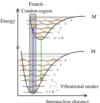
approximation (BOA). This energy is dependent on the internuclear distance of the several components in a molecule. For a diatomic molecule (M) and according to the BOA approximation, its energy potential curve can be plotted as in Figure 2.3. Also represented is the potential curve for the electronically excited molecule (M*, which in the case of
Figure 2.3, such is represented by the parent anion, M–).
Figure 2.3 - Born-Oppenheimer potential energy curves for a molecule in the ground state (M) and its electronically excited state (M–). Vertical transitions are shown representatively. Also represented are
the vibrational modes (ν) and the Franck-Codon region (shadow). Adapted from [3].
Energy
Internuclear distance M–
M
Vibrational modes
Franck-Condon region
9
2.3.
The Franck-Condon principle
Transitions between two electronic states can easily be described if one considers that they occur so rapidly that the internuclear distances of the molecule do not have enough time to change appreciably their position of equilibrium. This is known as the Franck-Condon principle. Hence an electronic transition between two states may be represented
by a vertical line joining the potential energy surfaces, originating from the most probable internuclear separation in the ground state [4]. The electronic transition from the ground-state to an electronically excited ground-state of a molecule occurs within the Franck-Condon region (see Figure 2.3), defined by the superposition of the vibrational wavefunctions of both states [5]. The probability of a transition from a vibrational level 𝑣 of the neutral to an excited vibrational level 𝑣′ of the upper electronic state is approximately given by the
Franck-Condon factor (FCF) [5]:
𝐹𝐶𝐹 = |〈(Ψ𝑣′|Ψ𝑣)〉|2 2.5
The Ψ𝑣 represents the vibrational wavefunction of the neutral ground state and Ψ𝑣′ is the vibrational wave function of the upper electronic state.
2.4.
Negative ion formation through electron attachment
Molecular dissociation can be triggered by the capture of an electron by a neutral molecule. In the context of this thesis two distinct mechanisms are identified: a) electron transfer; and b) dissociative electron attachment. In the electron transfer process, an electron is transfer from a neutral (A) or a negatively charged atom (A–) to a neutral molecule (BC). This process can be exemplified in the following equations [1]:
𝐴 + 𝐵𝐶 → 𝐴++ (𝐵𝐶)− 2.6
𝐴−+ 𝐵𝐶 → 𝐴 + (𝐵𝐶)− 2.7
10
electron attachment process is characterized by a capture of a free electron, schematically represented as:
𝑒−+ 𝐵𝐶 → 𝐵 + 𝐶− 2.8
2.4.1. Dissociative electron attachment
Free electron capture is a resonant process; the electron is trapped by the molecule/atom and produces a temporary negative ion (TNI). After the TNI’s formation, it
can decay by different processes: autodetachment, radiative stabilisation and dissociative
electron attachment. ABC represents a polyatomic molecule and “*” indicates the anionic
transient state.
𝑒−+ 𝐴𝐵𝐶 → (𝐴𝐵𝐶−)∗
(𝐴𝐵𝐶−)∗ ⟶ (𝐴𝐵𝐶)∗+ 𝑒− Autodetachment 2.9
(𝐴𝐵𝐶−)∗ ⟶ (𝐴𝐵𝐶)−+ ℎ𝜈 Radiative stabilization 2.10
(𝐴𝐵𝐶−)∗→ 𝐴𝐵−+ 𝐶 Dissociative electron attachment 2.11
(𝐴𝐵𝐶−)∗ → 𝐴𝐶− + 𝐵 Dissociative electron attachment
with rearrangement
2.12
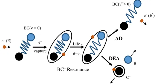
During the lifetime of the resonance, the presence of the extra electron in the system will incite the movement of the nuclei to larger distances [8]. In reaction (2.9) the TNI does not undergo into dissociation and goes back to the neutral state via spontaneous emission of the electron (see Figure 2.4). However, as briefly pointed out before (see sub-chapter 2.1.3), due to the long-time permanence of the extra electron, the neutral molecule can stay in an excited vibrational state [9]. Within the initial electronic state a reaction with 𝜈’ > 𝜈 and 𝑛 = 𝑛’ is a vibrational excitation (VE) [8]. 𝜈 represents the ground vibrational state and
𝜈’ is an excited vibrational state, while 𝑛 is the ground electronic quantum number and 𝑛’ corresponds to an electronic quantum number in the excited state.
11
range of 10-9– 10-8 s, this sort of reactions are slower than those in 2.9 and 2.11 . This will
make this process non-competitive with the others [1].
Reaction (2.11) describes the dissociative electron attachment channel. The TNI is unstable due to the temporary presence of an extra electron, which will change the intramolecular potential. The TNI decomposition will occur due to the excess of internal energy. In the course of the negative ion formation, the equilibrium internuclear distance of the state that leads to dissociation is overall higher than the equilibrium internuclear distance of the neutral molecule. This is the case, since the bond energy is reduced by the presence of an extra electron. If the DEA channel is available, it will strongly compete with the autodetachment channel [1]. Hence, depending on the autodetachment lifetime, the TNI can decay into the available anionic fragments and corresponding neutral fragments.
Figure 2.4 - Dynamics of Autodetachment (AD) and dissociative attachment (DEA) in electron-molecule scattering through resonances. 𝝂 represents a vibrational quantum number. Adapted from
[8].
Sometimes DEA does not progress directly via a purely repulsive energy surface, instead, it progresses through indirect processes such as electronic, vibrational predissociation or rearrangement of the precursor anion before it dissociates. Such example is shown in reaction 2.12, where internal rearrangement occurs. While reaction 2.11 represents a single cleavage of the B–C bond, reaction 2.12 represents the removal of B from the TNI with a cleavage of the A–B and B–C bonds and rearrangement of the neutral fragments to form AC. In this kind of reaction the energy gained by the formation of the
e–
capture BC(ν = 0)
Life -
time
AD e– (E)
BC(ν̕̕̕̕̕̕̕̕̕̕̕̕̕̕̕̕̕̕̕̕̕̕̕̕̕ ̕̕̕̕̕̕̕̕̕̕ ̕̕̕̕̕> 0)
e– (E̕̕̕̕̕ )
DEA
B
C–
12
stable neutral product AC can shift the threshold energy to lower values. The most ordinary rearrangements in a molecule are those containing hydrogen or fluorine [6].
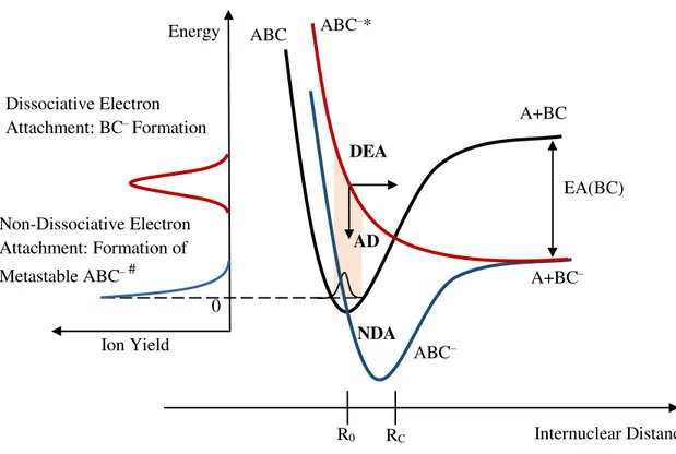
A schematic representation of the dynamics in a potential curve diagram of AD (autodetachment), DEA and NDA (non-dissociative electron attachment) is shown in Figure 2.5. A repulsive anionic potential energy curve in the Franck-Condon region is represented in red. AD is possible until the crossing point RC. In contrast with the red
potential curve, the blue potential curve has a minimum. If the excess of energy brought by the extra electron is released or redistributed into other vibrational degrees of freedom, the metastable ABC-# can be formed. On the left-hand side of Figure 2.5 it is represented a
sketch where is possible to infer on the ion yields corresponding to the formation of BC– (red curve) and ABC– (blue curve).
Figure 2.5 - Schematics of a potential curve for low energy electron interactions with a molecule ABC. Representation of possible decay processes: DEA (dissociative electron attachment), AD
(autodetachment) and NDA (non-dissociative electron attachment). Adapted from [6].
DEA
Internuclear Distance R0 RC
EA(BC) A+BC
A+BC–
ABC ABC–*
ABC– Ion Yield Energy 0 AD Non-Dissociative Electron
Attachment: Formation of Metastable ABC–#
Dissociative Electron Attachment: BC–Formation
13
Finally, DEA is also a bond and site selective process, i.e., site (N1-H vs N3-H)- and bond (C-H vs C-N)- selective dissociation in DNA/RNA pyrimidine bases can be achieved by tuning the proper electron energy [10].
2.4.2. Dipolar dissociation
While DEA is a resonant process that generally occurs at electron impact energies below ~15 eV, dipolar dissociation (DD) characterizes a direct excitation process of the target molecule and it takes place at higher energies [11]. DD involves dissociation of an electronically excited state into an ion-pair, i.e., it dissociates into a positively and
negatively charged fragment [12]:
𝑒−+ 𝐴𝐵 → (𝐴𝐵)∗+ 𝑒− → 𝐴++ 𝐵−+ 𝑒− 2.13
Its electron energy dependence usually consists of a monotonically increase from a threshold of the anion yield (in this example, B–) [12].
2.4.3. Electron transfer
The processes of collisional ionisation include every interaction between neutral particles in which an electron transfer occurs. From the many reactions possible, the reactions below resume the different electron transfer types studied in the present thesis:
One way of performing electron transfer experiments is to make use of an electron donor, i.e., an atom that has a weakly bound valence electron and under particular
experimental conditions can transfer it to a target molecule. Examples of this kind of atoms
are the alkaline metals (Na, K, Cs…) with particular low-ionisation energies. In the present work an experiment concerning electron transfer was used where the electron donor atom was potassium (K). Potassium has a relatively low ionisation energy, 4.34 eV [13], making it a good electron donor.
𝐴 + 𝐵𝐶 → 𝐴++ 𝐵𝐶− Nondissociative Ionization 2.14
14
The electron transfer in atom-molecule collisions depends on the crossing of the potential energies surfaces of the neutral complex 𝐴 + 𝐵𝐶 and the ionic 𝐴++ 𝐵𝐶−
involved in the collision process. According to Kleyn et al. [14], for large atom - molecule
distances, the ionic potential energy curve lies above the covalent, however due to the Coulombic potential of the collision complex (𝐴+𝐵𝐶–)∗ there is a crossing point in which
two curves have the same value (Rc). This interaction gives rise to a positive ion formation
and a molecular anion, i.e. ion-pair formation. During the molecular anion formation, the internuclear equilibrium distance corresponding to the state that leads to dissociation is in general always higher than the equilibrium distance of the neutral molecule, since the capture of an excess electron reduces the bonding energy [6]. In the Lisbon laboratory, potassium - molecule collisions are typically performed in the lab-frame range 15 – 300 eV, meaning that in the low energy collision regime (< 50 eV), the collision time (defined as the transit time of K+ after electron transfer and before leaving the strong Coulomb
interaction with the TNI) is of the same order as the vibrational period of particular modes (typically stretching). As a consequence, during the collision the target molecule may experience a gradual increasing of a particular bond (Rm), meaning that the electron affinity
(see next sub-chapter) is not limited to a fixed value. This process is known as bond-stretching [15].
Considering that the crossing point between covalent and ionic potential energy curves in the case of diatomic molecules (or surfaces in the case of polyatomic molecules) takes place at large atom-molecule distances, van der Waals and polarization interactions can be ignored, meaning that the ionic potential can be represented by a Coulombic potential only. Since in this point both potential energy curves (or surfaces) have the same value, the crossing point (Rc) in units of Å can be given by the following equation [14]:
𝑅𝑐 ≈ 𝑒 2
𝛥𝐸 =
14.41 𝐼𝐸 − 𝐸𝐴(𝑅𝑚)
2.16
where 𝐼𝐸 corresponds to the ionisation energy of the donor atom and 𝐸𝐴 corresponds to the electron affinity of the target atom (or molecule) [16], both in units of eV. The increase of the electron affinity results in an increase of the crossing distance.
15
potential energy surfaces involved in the interaction. In the case of ionic scattering, there are two crossing distances, i.e., one during approach, Rc1, and the other at departure Rc2
(>Rc1), see Figure 2.6. Rc2 depends on the collision velocity, which reflects the electron
affinity behaviour with Rm.
Figure 2.6 – Representation of the collision trajectories between an alkaline atom (A) and a molecule (M). The crossing radius corresponds to the external circle and the repulsive potential region is represented by the dashed area. When the electron is transferred at Rc1 the trajectory is known as
ionic, whereas at Rc2 the trajectory is termed covalent. Adapted from [14,17].
The transition between ionic and covalent states is only possible if the adiabatic principle is satisfied, i.e., if the collision partners get slowly closer to each other. In this
case, the target electrons have enough time to adjust themselves to the internuclear separation due to electron transfer. However, if the collision is fast enough, there is no time for such changes and no electron transfer will occur. In this case the system will keep the same electronic configuration [14], i.e. known as covalent. In an electron transfer process, the probability of occurring a non-adiabatic transition (𝑝) is given by the Landau-Zener model (for a comprehensive description see ref. [14]).
2.4.4. Electron affinity
The capability of a molecule to form a stable anion is denoted by the electron affinity (EA). It is defined as the energy difference between the molecule in its neutral ground state (M) and its anionic state (M–) [18]. Adiabatic electron affinity (EAad) refers to
Rc1 Rc2
M
16
both, the neutral and the anion, in their ground electronic, vibrational and rotational states [19].
Per definition the EA is negative if the electronic state M– lies above the neutral M, and it is positive if it lies below [1]. A positive value indicates the presence of a stable anion. In order to have a stable anion, the excess energy given by the attachment of the extra electron has to be dissipated by the molecule.
Figure 2.7 - Schematic diagrams of potential energies. Representation of the electron affinity (EA), vertical detachment energy (VDE) and vertical attachment energy (VAE). Adapt from [6].
𝐸𝐴(𝑀) = 𝐸(𝑀) + 𝐸(𝑀−) 2.17
M
M–
VDE (M-)
EA (M)>0eV ν = 0
ν' = 0
–
+ Energy
ν = 0
M*–
M+ e–
M*+ e–
VAE (M) ν*' = 0 ν* = 0
EA(M*)>0eV
VDE(M*–)
Internuclear distance Internuclear distance A–
–
+ A+ e–
EA (A)>0eV VDE (A-)
Energy A*+ e–
A*– EA(A*)>0eV
A + e–
a) b)
17
It is also important to define vertical attachment energy (VAE) and vertical detachment energy (VDE). VDE is the minimum energy necessary to detach the additional electron from the ground state of the negative ion [18]. No changes in the internuclear distance occur (see sub-chapter 2.3). On the other hand, the VAE corresponds to the difference in energy between the neutral molecule in its ground electronic state with an electron at infinity, and the formed anion. As in the case of VDE, in VAE no changes in the internuclear distance occur. Figure 2.7 shows a schematic of the EA, VDE and VAE representation. In Figure 2.7 a) and b) examples of when an atom captures an extra electron are shown. Figure 2.7 c) and d) show examples of when an electron is captured by a diatomic molecule. In Figure 2.7 a) it is possible to observe that the EA(A) and VDE(A–) are the same. This is the case where all transitions occurring in atoms are vertical. The internuclear distance cannot change, as there is only one nucleus. Figure 2.7 b) and d) represent the case where a Feshbach resonance is formed. The excess electron is attached to an excited atom or molecule, forming the anionic specie A*–, M*–. Feshbach resonances
and other types of resonances will be briefly described in the next sub-chapter.
2.4.5. One particle and two particle-one hole resonances
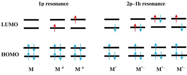
When an electron is captured by a molecule into its lowest unoccupied molecular orbital (LUMO) a resonance is formed. The LUMO usually has anti-bonding character [8].
Figure 2.8 - 1p resonance and 2p-h resonance electronic configuration. The red arrows represent the captured electron. Adapted from [20].
1p resonance 2p–1h resonance
LUMO
HOMO
18
The types of TNI observed in the present study are described by single particle (1p) and two particle-one hole (2p-1h) resonances (Figure 2.8). A 1p resonance is formed when the incoming electron occupies the LUMO. On the other hand, in a (2p-1h) resonance the incoming electron will excite at least one of the electrons of the molecule. Hence a hole is created in the electronic configuration as two electrons will occupy the LUMO [21].
Figure 2.9 - Classification of the different types of resonance according to their energy in comparison to the neutral parent (M). Adapted from [1].
A way to categorize the resonances can be done through the difference in energy between the neutral and the excited molecule (Figure 2.9). In a one particle resonance, the interaction between the incident electron and the neutral in the ground state origins a potential well where the incident electron will be trapped. This mechanism is described by the effective potential, which consists of the attractive polarization interaction and repulsive centrifugal potential. The attractive polarization interaction is given by [22]:
𝑉𝑎(𝑟) = −𝛼𝑞 2
2𝑟4 2.18
where the induced dipolar attraction (𝑉𝑎(𝑟)) is defined by the polarization (𝛼) of the target molecule, the distance between the incoming electron and the molecule (𝑟) and by the elementary charge (𝑞).
0 Energy
M*
M
Core excited shape
Feshbach
Neutral Negative Ion
Shape
19
Figure 2.10 - Representation of the effective potential of the electron-molecule interactions depending on their distance (r). Depending on the angular momentum, different potential barriers are formed.
For l = 0, no potential barrier is formed, while for l ≠ 0 a centrifugal barrier is created and the electron can be momentarily trapped inside the effective potential. Adapted from [21].
The repulsive centrifugal potential (𝑉𝑙(𝑟)) is given by [22]:
𝑉𝑙(𝑟) =ℏ
2𝑙(𝑙 + 1)
2𝑟2𝜇 2.19
where 𝑙 represents the electron angular momentum and 𝜇 is the reduced mass of the molecule-electron system. This will originate a centrifugal barrier in which the extra electron can be momentarily confined. Thus, the effective potential has the form:
𝑉𝑒𝑓𝑓(𝑟) = 𝑉𝑙(𝑟) + 𝑉𝑎(𝑟) =ℏ
2𝑙(𝑙 + 1)
2𝑟2𝜇 −
𝛼𝑞2
2𝑟4 2.20
The effective potential for different angular momentum quantum numbers (𝑙 = 0, 1 and 2) is represented in Figure 2.10. When 𝑙 ≠ 0 a centrifugal barrier is created and an electron can be momentarily trapped inside it. These are known as shape resonances [23,24], since the extra electron is trapped by the shape of the potential. In a shape resonance the electronic state of the TNI lies above (in energy) the neutral state (Figure 2.9). The lifetime of this resonance is short (10-15 – 10-10 s) [23], due to the possible
l=1 l=2
l=0 0
Energy (eV)
20
tunneling of the electron through the potential barrier. The TNI decay is further dictated by the competition of dissociation with autodetachment. The TNI decays back to the parent electronic state, which frequently includes vibrational excitation [24]. These resonances are also referred as one particle resonances. The energies of these resonances in electron-molecule experiments are usually found below 4 eV [23]. On the other hand for the case where the angular momentum is zero (𝑙 = 0) no barrier is created.
Figure 2.11 – Representation of a dipole bound state or also called vibrational Feshbach resonance, since its vibrational levels are below the corresponding levels of the neutral. Adapted from [25].
A vibrational or nuclear Feshbach resonance (Figure 2.11) is still a 1p resonance, however in this type of resonance the energy of the TNI produced is below the ground state of the neutral [8]. This means that molecules with this type of resonances have a positive electron affinity (EA) and are likely to have large polarizability or a very large dipole moment (>2.5 D) [21].
In a core-excited resonance or two particle-one hole (2p-1h) resonance, the energy of the incoming electron is high enough to induce an electronic excitation. Two electrons will occupy molecular orbitals (MO) which are typically empty [26] (see Figure 2.8). These resonances take place at energies near to the electronic excitation energies and usually lead to TNIs that lie energetically above the electronically excited parent state of the neutral molecule [21]. A centrifugal barrier is bounding the electron as in the 1p resonance case [21]. As seen before, the potential barrier is dependent on the 𝑙 value of the occupied excited
Internuclear Distance A+B
A+B–
AB Energy
0
21
state orbital, therefore no electrons with zero angular momentum can be attached (at least by such barrier). This type of resonances can decay by autodetachment or dissociative attachment, having a typical lifetime of the order of 10-3– 10-2 s [20].
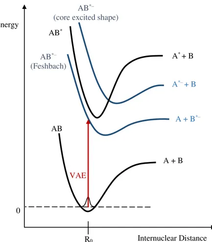
Figure 2.12 – Scheme of a potential energy diagram where the neutral ground state and electronically excited state of molecule AB is visible. Core exited shape and Feshbach resonances are also
represented. Adapted from [21].
A Feshbach resonance (Figure 2.9 and Figure 2.12) is characterized by the TNI having a lower energy than the excited neutral [8]. The electron affinity of the excited neutral is thus positive. In order to dissociation take place, the captured electron needs to get the energy before reemission becomes energetically available. For a decay process into the neutral ground state a change of the electronic configuration is required. The autodetachment lifetime of the anion is thus significantly longer [9].
Internuclear Distance R0
A + B
A + B*–
AB
AB*–
(core excited shape)
Energy
AB*–
(Feshbach)
A*–+ B
0
VAE AB*
22
2.4.6. Metastable ions
When an ion is formed, it can have enough internal energy to dissociate before being detected. Concerning the ions stability, in mass spectrometric time scale there is a terminology that categorize three different types of ions: stable, unstable and metastable ions [5]. Stable ions are those that do not decompose or have decomposing rates ≲ 105 s-1,
therefore they will reach the detector without being fragmented [5]. On the other hand unstable ions decompose before reaching the detector, having dissociating rates > 106 s-1
[5]. They are unable to be detected. The third type of ions are known as metastable and have decomposing rates of 105– 106 s-1 [5,18].They are defined as ions that are formed in
the ion source (parent ions), but decay into fragments (daughter ions) while on their transit through the mass analyser system. This process is called metastable decomposition [27].
23
References
[1] E. Illenberger, J. Momigny, Gaseous Molecular Ions. An Introduction to Elementary Processes Induced by Ionization, Steinkopff/Springer, New York, 1992.
[2] S. Denifl, PhD thesis, University of Innsbruck, Innsbruck, 2004.
[3]
http://de.wikipedia.org/wiki/Franck-Condon-Prinzip#mediaviewer/Datei:Franck-Condon-Prinzip.svg, (Accessed on June 2014).
[4] E. Condon, Phys. Rev. 28 (1926) 1182.
[5] J.H. Gross, Mass Spectrometry, Springer Verlag, Germany, 2004.
[6] L.G. Christophorou;, Electron-Molecule Interactions and Their Applications, Academic Press, London, 1984.
[7] T.D. Märk, G.H. Dunn, Electron impact ionization, Springer Verlag, Vienna, 1984.
[8] H. Hotop, M.W. Ruf, M. Allan, I.I. Fabrikant, Advances In Atomic, Molecular, and Optical Physics, Academic Press, 2003.
[9] A. Edtbauer, PhD Thesis, University of Innsbruck, Innsbruck, 2010.
[10] S. Ptasinska, S. Denifl, V. Grill, T.D. Mark, E. Illenberger, P. Scheier, Phys. Rev. Lett. 95 (2005) 4.
[11] E. Szymanska, N.J. Mason, E. Krishnakumar, C. Matias, A. Mauracher, P. Scheier, S. Denifl, Int. J. Mass Spectrom. 365 (2014) 356.
[12] M. Bazin, S. Ptasinska, A.D. Bass, L. Sanche, Phys. Chem. Chem. Phys. 11 (2009) 1610.
[13] R.L. Kelly, J. Phys. Chem. Ref. Data 16 (1987) 1.
[14] A.W. Kleyn, J. Los, E.A. Gislason, Phys. Rep.-Rev. Sec. Phys. Lett. 90 (1982) 1.
24
[16] D. Almeida, PhD, Universidade Nova de Lisboa, Lisboa, 2013.
[17] A.W. Kleyn, A.M.C. Moutinho, J. Phys. B-At. Mol. Opt. Phys. 34 (2001) R1.
[18] F. Ferreira-da-Silva, PhD thesis, University of Innsbruck, Innsbruck, 2009.
[19] E. Illenberger, Chem. Rev. 92 (1992) 1589.
[20] F.R. Ferreira-da-Silva, PhD thesis, University of Innsbruck, Innsbruck, 2009.
[21] I. Bald, J. Langer, P. Tegeder, O. Ingolfsson, Int. J. Mass Spectrom. 277 (2008) 4.
[22] O. Ingolfsson, F. Weik, E. Illenberger, Int. J. Mass Spectrom. Ion Process. 155 (1996) 1.
[23] G.J. Schulz, Rev. Mod. Phys. 45 (1973) 423.
[24] M. Allan, J. Electron Spectrosc. Relat. Phenom. 48 (1989) 219.
[25] I. Bald, Doktors der Naturwissenschaften thesis, Freien Universität Berlin, Berlin, 2007.
[26] Y. Yildirim, M. Balcan, A. Kinal, A.D. Bass, P. Cloutier, L. Sanche, Eur. Phys. J. D 66 (2012) 12.
25
3.
Experimental set-up
n this chapter a brief description of the experimental set-ups used to perform the experimental work presented in this thesis is done. In order to study dissociative electron attachment (DEA) processes as well as electron transfer processes, two set-ups were used: a double focusing mass spectrometer at the institute for Ion Physics and Applied Physics, University of Innsbruck, Austria and a crossed molecular beam apparatus equipped with a time of flight mass spectrometer at the Atomic and Molecular Collisions Laboratory, Universidade Nova de Lisboa, Portugal.
3.1.
Apparatus used to perform DEA experiments
Figure 3.1 – Schematics of the double focusing spectrometer used to perform DEA experiments [1].
All DEA experiments were carried out at the Institute for Ion Physics and Applied Physics, University of Innsbruck, Austria. The mass and energy spectra for all the DEA studies were obtained using a double focusing mass spectrometer in a reverse Nier-Johnson geometry. In Figure 3.1 a schematics of the experimental set-up can be found. The mass
26
spectrometer is named double focusing because it combines both directional focusing and energy focusing. It is said to have a reversed geometry because, contrary to a standard double focusing spectrometer, the magnetic sector is prior to the electric sector. Briefly, this apparatus consists of an ion source, a first field free region, a magnetic field, a second field free region, an electric field and a channeltron detector. The set-up works in high vacuum conditions (typical base pressure of ≈ 2 × 10⁻⁷ mbar), which is secured by turbo
pumps connected to rotatory pumps. Under normal circumstances this apparatus presents a mass resolution of ~1100 and an energy resolution of ~1 eV. The next sub-chapters present some of the main sector field components.
3.1.1. Introducing a sample in the chamber
Prior to sample interaction with the beam of electrons, the sample has to be transferred into highly diluted gas phase [2]. Taking into account the primitive phase of the compound (solid, liquid or gas) different inlet systems were used.
Figure 3.2 – a) Picture of the VG-ZAB ion source chamber and gas and liquid inlets. A heating band and aluminium foil is wrapped around the liquid inlet. b) Detailed view of the ion source and
capillary.
3.1.1.1. Gas phase sample
When in the gas phase, a gas sample is considered highly diluted when the mean free path for the particles is so long that bimolecular interactions are barely happening [2].
Ion source
Capillary
Reservoir
Gas inlet SF6 bottle
Liquid inlet
Thermocoax
27
This is usually the case for background pressures in the chamber of the order of < 10 mbar.
All the samples studied in the gas phase were introduced in the ion source chamber through an inlet as shown in Figure 3.2. The inlet is attached to the ion source chamber. Through two valves (that are part of the inlet system) it is possible to control the gas pressure in the ion source chamber. These two valves allow safety (bellow-seal valve) and sensitive (needle valve) control of the pressure. SF6 is also introduced in the chamber
through this inlet. SF6 is the gas used to calibrate the energy and mass scales (for more
information about calibration see sub-chapter 3.1.8).
3.1.1.2. Liquid phase sample
In order to measure liquid samples an inlet as the one shown in Figure 3.2 a) was used. The liquid sample is kept in a reservoir and is introduced in the ion source chamber by opening the set of valves in the inlet liquid system. As in the gas inlet (sub chapter 3.1.1.2), the liquid inlet also has two valves. The valves allow safety (bellow-seal valve) and sensitive (needle valve) control of the pressure in the ion source chamber. The flange where this line is attached has an incorporated capillary that is aligned to end directly to one of the holes of the ion source block, as shown in Figure 3.2 b). The distance between the ion block and the end of the capillarity is less than 0.5 cm.
Not all liquids have a high vapour pressure and thus a heating system is required to increase their vapour pressures. Outside the chamber the heating system is composed of a heating band, while the capillarity is heated by thermocoax wire. Both temperatures are monitored by thermocouple sensors.
Before opening the valve and introducing the sample into the ion source chamber, several freeze-pump-cycles must be done. This procedure is done in order to get rid of volatile contaminations within the sample.
3.1.1.3. Solid phase sample
28
temperature is measured by a thermocouple. The oven is placed inside the ion chamber and the exit hole is facing a slit of the ion block by less than 0.5 cm apart.
3.1.2. Ion source
In the ion source, an effusive beam of molecules is introduced and made to cross with an electron beam. In Figure 3.3 a schematic drawing of the ion block is shown. The electron beam is produced by the heating of a tungsten rhenium filament with a diameter of 0.178 mm by means of an electric current of around 3-4 A and by applying an acceleration voltage. The electron beam energy distribution is given by [3]:
𝑑𝑁(𝐸) ∝ 𝑒[−𝑊+𝐸𝑘𝑇 ]𝑑𝐸 3.1
where 𝑑𝑁(𝐸) is the number of electrons emitted per second between energies 𝐸 and 𝐸 +
𝑑𝐸, 𝑊 represents the work function of the metal, 𝑇 is the absolute temperature, whereas 𝑘 is the Boltzmann constant. This means that electrons have a Maxwell-Boltzmann distribution, which in the current geometry they show an energy spread of ~1eV at full width at half maximum (FWHM).
Figure 3.3 - Schematics of the ion block. Adapted from [4].
29
After electrons being produced, they are accelerated towards the ion source block by applying a potential difference between the filament and the ion source block (see Figure 3.3). The electron beam is collected at the so called trap, where the trap current regulation is used to control and monitor the filament current, i.e. the electron emission performance. In order to prevent, as much as possible, the electron beam spreading in the ion block, outside the source there are two magnets placed so as to attract each other [4]. The electron beam will then follow the magnetic flux lines created by the set of magnets. The ions are extracted from the source by means of an electric field (a potential difference of 6 kV is applied between the ion source block and the fixed source slit, which is at ground potential). The usual background pressure in the ion source chamber is ≈ 2 × 10⁻⁷ mbar (sometimes lower ≈7 × 10⁻⁸ mbar). This value depends on how clean the chamber is and for how long it has been pumped out. When measurements are performed, pressures up to
5 × 10⁻⁵ mbar are used upon sample admission. The typical pressure value used in the ion
source will strongly depend on the sample being probed. The ion source chamber is isolated from the mass analyser by a valve. This allows opening the ion source chamber without breaking the vacuum in the other parts of the set-up.
3.1.3. Mass analysis of ions
After the production of the ions upon electron-molecule interactions, they will enter a first field free region and will be analysed by their momentum in a magnetic sector. The following equation describes the kinetic energy of the ion when entering the magnetic field [4]:
𝑞𝑈 =12 𝑚𝑣2 3.2
where 𝑈 corresponds to the potential difference applied in the ion block in order to remove the ions from it; 𝑚, 𝑞 and 𝑣 are the mass, the charge and the velocity of the ion, respectively. The next equation describes the magnetic force imposed to a charged particle:
𝐹⃗𝑚 = 𝑞𝑣⃗ × 𝐵⃗⃗ 3.3
30
𝑚𝑣2
𝑟 = 𝑞𝑣𝐵 ⟺ 𝑟 = 𝑚𝑣 𝑞𝐵
3.4
Considering that the ions have a specific kinetic energy, the final equation can be shown as:
𝑚 𝑞 =
𝐵2𝑟2
2𝑈
3.5
Bearing in mind equation 3.5, if a constant field strength and a constant voltage are applied and considering that the ions produced are singly charged, then the mass will be directly proportional to the square radius of the arch of the ions. Hence, for a given 𝐵, ions can be differentiated by their mass over charge ratio. It is possible to measure the different masses just by changing the magnetic field or the voltage.
The magnet also allows focusing a diverging ion beam that enters the field. The magnet is known to be directional focusing. However, so far, it was assumed that all ions entering the magnetic field have exactly the same kinetic energy. This is not entirely true, since there is some energy spread. Consequently, if the ions would be detected after the magnetic field, the result would be a blurred image. If the equation for the kinetic energy and equation 3.5, are taken into account:
𝑟 =√2𝑚𝐸𝑞𝐵 𝑘 3.6
Then it is possible to see that for ions with the same mass and charge, can be dispersed by their kinetic energy (𝐸𝑘). Thus what is in need (after the momentum is selected) is an energy focus, since the magnet has no energy focusing effect.
3.1.4. The Electrostatic Analyser and Magnet Combination
As presented in the previous sub-chapter 3.1.3, the ions that leave the ion source do not have the same kinetic energy. This will lead to an energy dispersion effect. To correct this, an electrostatic analyser (ESA) is present in combination with the magnet, resulting in a double focusing system: direction and energy. After the ions pass the magnet they will
enter a second field free region and then the ESA. The electric force (𝐹⃗𝑒) in an electric field
31
𝐹⃗𝑒 = 𝑞𝐸⃗⃗ 3.7
The present ESA has a radial electric field, hence the velocity of the ions that enter the ESA is always perpendicular to the electric field. As a result, equation 3.7 can be rewritten as:
𝑞𝐸 =𝑚𝑣𝑟2 3.8
Knowing that the kinetic energy is expressed as 𝐸𝑘 = 1
2𝑚𝑣2, 𝑟 is then given by:
𝑟 =2𝐸𝑘
𝑞𝐸 3.9
From equation 3.9 it can be seen that an ESA does not analyse masses, it analyses the kinetic energy of the ions. The combination of a magnet with an electrostatic analyser will allow an inherent energy spread of the beam to be compensated, i.e. although with
different energies, ions with the same mass re-converge and can then be detected by the channeltron.
3.1.5. Detection: Channeltron
The ions are detected by a channeltron (or channel electron mutiplier) schematically represented in Figure 3.4. A channeltron is an electron multiplier device operated in the single pulse counting regime. This means that when primary charged particles enter and hit the high surface resistance of the channeltron’s walls, they will produce the emission of secondary electrons [5]. The secondary electrons will then be accelerated through the channel (see Figure 3.4) by a positive bias (potential difference between the entrance and output) hitting the wall and producing additional secondary electrons. This secondary electrons formation will keep on until an output pulse charge with up to 108 electrons is
32
Figure 3.4 - Production of secondary electrons in a channel electron multiplier. The output will be amplified and discriminated by a preamplifier discriminator unit which will trigger a counter. This
signal will be processed by a computer. Adapted from [5,6].
3.1.6. Mass resolution
According to Marshall’s [7] definition of mass resolution, two peaks are said to be resolved if the valley between them is equal to 10% of either peak height. The ability that a mass analyser has to distinguish between two ions with a small m/z difference (𝛿𝑚) is given by the mass resolving power (𝑅𝑚) [8]:
𝑅𝑚 =𝛿𝑚𝑚 3.10
However, it is also possible to define the mass resolution of an isolated peak by using the peak width 𝛿𝑚 at 50% of the peak maximum yield i.e. the full width at half maximum (FWHM) [8].
3.1.7. Measurements
3.1.7.1. Energy and mass scans
In order to perform energy scans for a certain ion, the mass of that ion has to be fixed and the electron energy is scanned over the intended range. The energy is scanned over several runs, and the runs are averaged over the total number. The number of runs performed and the time gate used depends on the signal statistics. Just for curiosity, in the
output
Funnel entrance
Channel
discriminator + preamplifier