Manuel Duarte Ribeiro da Cruz
Degree in Computer Science and Engineering
Understanding and evaluating the Behaviour of
DNS resolvers
Dissertation submitted in partial fulfillment of the requirements for the degree of
Master of Science in
Computer Science and Engineering
Co-advisers: José Legatheux, Professor, NOVA University of Lisbon João Leitão, Professor, NOVA University of Lisbon Eduardo Duarte, Technical Director, Association DNS.PT
Examination Committee
Understanding and evaluating the Behaviour of DNS resolvers
Copyright © Manuel Duarte Ribeiro da Cruz, Faculty of Sciences and Technology, NOVA University of Lisbon.
A c k n o w l e d g e m e n t s
To begin with, I would like to thank my three advisers, Professor José Legatheux, Professor João Leitão and Technical Director Eduardo Duarte for all their support, criticism, insight and for always being available to help whenever I required.
I would like to thank FCT-UNL and DNS.pt for the opportunity to work on this project, as well as all the help that was provided, through resources and tools that were offered to
be used.
I would also like to thank my classmates and friends, specifically André Catela, Fran-cisco Cardoso, João Santos, Paulo Aires, Ricardo Fernandes and Tiago Castanho, who supported me through this endeavour of five years, always being by my side and motivat-ing me to keep gomotivat-ing. Thanks for proof-readmotivat-ing this document and actmotivat-ing as an extra set of eyes.
Finally, I would like to thank my parents, my brother, and Inês Garcez for always being present, supportive and also proof-reading this document. They were an instrumental part in guiding me through this five year journey, and I can safely say that I wouldn’t be here without any of them.
A b s t r a c t
The Domain Name System is a core service of the Internet, as every computer relies on it to translate names into IP addresses, which are then utilised to communicate with each other. In order to translate the names into IP addresses, computers resort to a special server, called a resolver. A resolver is a special DNS server that knows the DNS structure and is able to navigate the huge number of DNS servers in order to find the final answer to a query. It is important for a resolver to be able to deliver the final answer as quickly as possible, to have the smallest impact on user experienced latency.
Since there is a very large amount of domains and servers, and the system is highly replicated, there has to be some logic as to how a resolver selects which server to query.
This brings us to the problem we will study in this thesis: how do resolvers select which DNS server to contact? If a resolver always selects the best DNS server - the one that will be able to provide the answer to the query the fastest - then resolvers can more quickly answer their clients, and thus speed up the Internet. However, if they contact different, more or less equivalent, servers they could contribute to load balancing.
To understand how exactly the resolvers select the DNS servers to contact, we con-ducted an experimental study, where we analysed different resolvers and evaluated how
they select the servers. We base the structure and parameters of our study in previous research that has been conducted on the topic, which shows that resolvers tend to use the latency of its queries to the servers as a means of selecting which server to contact.
R e s u m o
O Domain Name System é um serviço chave daInternet, uma vez que todos os com-putadores o utilizam para traduzir nomes (domínios) em endereços de IP, que são, por sua vez, utilizados para comunicar com outros computadores. Para conseguir traduzir os nomes em endereços de IP, os computadores contactam um servidor especial, chamado
resolver. Umresolveré um servidor DNS especial que conhece a estrutura do DNS e é
capaz de navegar o elevado número de servidores DNS, com o intuito de obter a resposta final a uma pergunta feita ao servidor. É importante que oresolverconsiga devolver a resposta final o mais rapidamente possível, de modo a ter o mínimo impacto na latência sentida pelos utilizadores.
Uma vez que existe um número muito elevado de domínios e de servidores, e como o sistema é fortemente replicado, é necessário que exista alguma lógica que dite o processo que oresolverexecuta para selecionar o servidor para questionar.
A necessidade desta lógica traz-nos ao problema em concreto: como é que osresolvers
selecionam qual o servidor DNS que irão contactar? Se umresolverconseguir sempre
es-colher o melhor servidor (o servidor que consegue fornecer a resposta à pergunta efetuada mais rapidamente) então oresolverconsegue responder ao cliente mais rapidamente, e, portanto, aumentar a velocidade daInternet. No caso em que existam vários
servido-res com latências iguais, os servido-resolvers poderão também ajudar com oload balancingda rede.
Para compreender como é que osresolversselecionam o servidor DNS a contactar,
conduzimos um estudo experimental, onde analisamos vários resolvers e avaliamos como é que estes selecionam os servidores. Baseamos a estrutura e parâmetros do nosso estudo nos resultados obtidos em estudos prévios, que mostram que osresolverstendem
a utilizar a latência das suas queries como uma medida de seleção de servidores.
C o n t e n t s
List of Figures 15
List of Tables 17
Listings 19
Glossary 21
1 Introduction 1
2 The Domain Name System 5
2.1 Overview . . . 5
2.2 DNS Structure as a distributed system . . . 6
2.2.1 Replication. . . 6
2.3 Queries . . . 8
2.4 Performance . . . 9
2.5 Summary . . . 10
3 Related Work 11 3.1 DNS Performance . . . 12
3.2 Authoritative server selection by the resolvers . . . 13
3.2.1 Least SRTT. . . 13
3.2.2 Statistical Selection . . . 14
3.2.3 Measurements . . . 14
3.3 Anycast . . . 17
3.4 Summary . . . 21
4 Test Bed 23 4.1 Overview . . . 23
4.2 Necessary Machines . . . 24
4.2.1 Client . . . 24
4.2.2 Sniffer . . . 25
4.2.3 Authoritative Servers . . . 25
C O N T E N T S
4.3 Individual Tools . . . 27
4.3.1 DNSJit . . . 28
4.3.2 Query Generator . . . 29
4.4 Tests. . . 30
4.4.1 Standard Tests . . . 31
4.4.2 Latency Cut-offTests . . . 31
4.4.3 Packet Loss Tests . . . 31
4.4.4 Network Topology Change Tests . . . 31
4.4.5 Random Query Rate Tests . . . 32
5 Results 33 5.1 BIND . . . 34
5.1.1 Standard Tests . . . 34
5.1.2 Latency Cut-offTests . . . 35
5.1.3 Packet Loss Tests . . . 36
5.1.4 Network Topology Change Test . . . 37
5.1.5 Random Query Rate Test . . . 38
5.2 PowerDNS . . . 39
5.2.1 Standard Tests . . . 39
5.2.2 Latency Cut-offTests . . . 39
5.2.3 Packet Loss Tests . . . 40
5.2.4 Network Topology Change Test . . . 41
5.2.5 Random Query Rate and Interval Test . . . 42
5.3 Unbound . . . 43
5.3.1 Standard Tests . . . 43
5.3.2 Latency Cut-offTests . . . 44
5.3.3 Packet Loss Tests . . . 45
5.3.4 Network Topology Change Test . . . 46
5.3.5 Random Query Rate and Interval Test . . . 47
5.4 Windows12. . . 48
5.4.1 Standard Tests . . . 48
5.4.2 Latency Cut-offTests . . . 49
5.4.3 Packet Loss Tests . . . 51
5.4.4 Network Topology Change Test . . . 52
5.4.5 Random Query Rate and Interval Test . . . 53
5.5 Client POV and Conclusion . . . 54
6 Conclusions 57
Bibliography 59
I Annex 1 61
C O N T E N T S
I.1 Bind Graphs . . . 61
I.2 PowerDNS Graphs. . . 63
I.3 Unbound Graphs . . . 64
I.4 Windows12 Graphs . . . 65
II Annex 2 67 II.1 Analyse Results . . . 67
II.2 Draw Graph . . . 71
II.3 Client POV . . . 75
L i s t o f F i g u r e s
2.1 The overall structure of DNS, adapted from [2] . . . 6
2.2 A client’s browser requesting the IP address of www.wikipedia.org, adapted from [7] . . . 7
3.1 Locations of more than 7,900 vantage points from RIPE Atlas, taken from [11] 16 4.1 Test bed . . . 24
4.2 Configuration file of authoritative servers of the root and .net domains . . . 26
4.3 Configuration file where we load the root zone . . . 26
4.4 Root zone file . . . 26
4.5 .Net zone file . . . 27
4.6 .Net zone file . . . 27
4.7 Windows root hints . . . 28
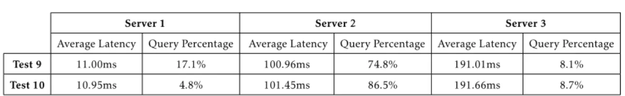
5.1 BIND Test 9 . . . 36
5.2 BIND Test 10 . . . 36
5.3 Bind Test 11 . . . 37
5.4 Bind Test 11, with failed queries shown. . . 37
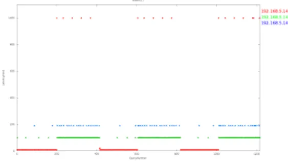
5.5 BIND Test 12 . . . 38
5.6 PowerDNS Test 9 . . . 40
5.7 PowerDNS Test 10 . . . 40
5.8 PowerDNS Test 11 . . . 41
5.9 PowerDNS Test 11, with failed queries shown . . . 41
5.10 PowerDNS Test 12 . . . 42
5.11 Unbound Test 1 . . . 43
5.12 Unbound Test 2 . . . 43
5.13 Unbound Test 9 . . . 45
5.14 Unbound Test 9 with dropped packets . . . 45
5.15 Unbound Test 11 . . . 46
5.16 Unbound Test 11, with failed queries shown . . . 46
5.17 Unbound Test 12 . . . 47
5.18 Windows12 Test 1 . . . 48
L i s t o f F i g u r e s
5.20 Windows12 Test 9, with failed queries shown . . . 51
5.21 Windows12 Test 11 . . . 52
I.1 BIND Test 1 . . . 61
I.2 BIND Test 2 . . . 61
I.3 BIND Test 3 . . . 61
I.4 BIND Test 4 . . . 61
I.5 BIND Test 5 . . . 62
I.6 BIND Test 6 . . . 62
I.7 BIND Test 7 . . . 62
I.8 BIND Test 8 . . . 62
I.9 PowerDNS Test 1 . . . 63
I.10 PowerDNS Test 2 . . . 63
I.11 PowerDNS Test 3 . . . 63
I.12 PowerDNS Test 4 . . . 63
I.13 PowerDNS Test 5 . . . 63
I.14 PowerDNS Test 6 . . . 63
I.15 PowerDNS Test 7 . . . 63
I.16 PowerDNS Test 8 . . . 63
I.17 Unbound Test 3 . . . 64
I.18 Unbound Test 4 . . . 64
I.19 Unbound Test 5 . . . 64
I.20 Unbound Test 6 . . . 64
I.21 Unbound Test 7 . . . 64
I.22 Unbound Test 8 . . . 64
I.23 Unbound Test 10 . . . 64
I.24 Unbound Test 10 with dropped packets . . . 64
I.25 Windows12 Test 2 . . . 65
I.26 Windows12 Test 3 . . . 65
I.27 Windows12 Test 4 . . . 65
I.28 Windows12 Test 5 . . . 65
I.29 Windows12 Test 7 . . . 65
I.30 Windows12 Test 8 . . . 65
I.31 Windows12 Test 9 . . . 65
I.32 Windows12 Test 10 . . . 65
L i s t o f Ta b l e s
3.1 Median delay of specific Internet components without inflation from lower
layers . . . 12
3.2 Distribution of PlanetLab nodes around the world, taken from [17]. . . 18
4.1 Tests designed to evaluate resolvers . . . 30
5.1 Results of the Standard Tests category of the Bind resolver . . . 34
5.2 Results of the Latency Cut-offTests category from the Bind resolver . . . 35
5.3 Results of the Packet Loss Tests category from the Bind resolver. . . 36
5.4 Results of the Network Topology Change Tests category from the Bind resolver 37 5.5 Results of the Random Query Rate Tests category from the Bind resolver . . 38
5.6 Results of the Standard Tests category of the PowerDNS resolver . . . 39
5.7 Results of the Latency Cut-offTests category from the PowerDNS resolver . . 39
5.8 Results of the Packet Loss Tests category from the PowerDNS resolver . . . . 40
5.9 Results of the Network Topology Change Tests category from the PowerDNS resolver . . . 41
5.10 Results of the Random Query Rate Tests category from the PowerDNS resolver 42 5.11 Results of the Standard Tests category of the Unbound resolver . . . 43
5.12 Results of the Latency Cut-offTests category from the Unbound resolver . . 44
5.13 Results of the Packet Loss Tests category from the Unbound resolver . . . 45
5.14 Results of the Network Topology Change Tests category from the Unbound resolver . . . 46
5.15 Results of the Random Query Rate Tests category from the Unbound resolver 47 5.16 Results of the Standard Tests category of the Windows12 resolver . . . 48
5.17 Results of the Latency Cut-offTests category from the Windows12 resolver . 49 5.18 Results of the Packet Loss Tests category from the Windows12 resolver . . . 51
5.19 Results of the Network Topology Change Tests category from the Windows12 resolver . . . 52
5.20 Results of the Random Query Rate Tests category from the Windows12 resolver 53 5.21 Average latency experienced from the client point of view . . . 54
L i s t i n g s
analyse_match.lua . . . 67
draw_graph.lua . . . 71
analyse_client_pov.lua . . . 75
G l o s s a r y
authoritative name server a server that contains a valid and up to date copy of a zone.
caching only server (also called a resolver)
a special server designed to traverse the DNS tree and cache the responses.
ccTLD Country code top level domain. It is a domain under the root, associated with a country code (such as .pt, .br, .es), as defined by the United Nation’s ISO 3166.
gTLD Generic top level domain. It is a domain under the root, not associated with a country, such as .com , .org, .info.
name server A server that associates a name of a resource to properties of said resource, as for example the resource’s IP address.
Resource Record An entry in the DNS database. A RR is associated with a domain name and contains a type, a value of that type and its validity time (TTL).
G L O S SA RY
TTL Time To Live represents how long (time or iterations of a pro-tocol) a certain piece of information is considered to be up to date.
zone A zone is a contiguous subsection of the domain space and includes all the information related to one or more of its sub-domains.
C
h
a
p
t
e
r
1
I n t r o d u c t i o n
The Domain Name System (DNS) is crucial to the performance and ease of use of Inter-net applications. DNS is essentially used to translate domain names into IP addresses, which are then utilized by the computers to communicate with each other. If DNS did not exist, every single user would have to know the physical IP address of every single machine that they wished to connect to, be it a friend’s computer or a website’s server. The existence of DNS also solves another problem, which consists in the occasional need to relocate or otherwise change the physical IP address of a server, since it introduces an indirection between names and addresses. With DNS, it is as simple as changing the IP field associated with the server name. Without it, it would be necessary to inform every single user of the new IP address, and every single user would then need to memorize the new IP address.
DNS is, fundamentally, a database, that maps domain names with a number of at-tributes, such as the IP address. Due to the enormous amounts of records within DNS, and the extremely large number of queries per second, it is mandatory to implement it as a heavily distributed database.
DNS is structured as a hierarchy of servers, divided by the domain names that they contain information on. This further decentralizes the database, diminishing the need for extremely powerful servers, as each server only needs to handle a specific subset of data. Since each server also handles less information, it allows them to operate faster. DNS is also heavily replicated in order to provide high availability, as the odds of all the servers regarding a specific subset of data being unreachable is quite low. The fact that it is heavily replicated also helps in providing good geographical coverage, since there are multiple instances of the same server all over the world.
C H A P T E R 1 . I N T R O D U C T I O N
of queries that have to be responded by consulting (external) servers diminishes consider-ably, speeding up the overall process of a DNS query. There are special DNS servers that are used solely to cache responses and resolve DNS queries, called resolvers or caching only servers.
A DNS server often can’t fully respond to a query. When this is the case, it generally sends the client the necessary information to reach a server that can actually answer the query. This means that, in order to obtain the desired answer to a DNS query, one must often travel the domain name tree. Resolvers also provide that service, along with caching the responses.
Thus, a resolver is a special type of DNS server, that serves to resolve DNS queries. Resolvers cache the responses they obtain from the servers to avoid repeating queries to the external network. These responses can only be cached for so long before they are no longer usable. How long they can be cached for is a parameter in the DNS database entry.
Resolvers are a vital part of DNS, as without them every single client would need to have a private way to traverse the DNS tree. If everyone had a private resolver, caching would not have nearly as much effect as it currently has, since the number of DNS queries
would be much larger. Resolvers are generally managed privately, by the Internet Service Provider(ISP) or openly, such as GoogleDNS and OpenDNS.
Since there is a large number of DNS servers that contain the same data, the resolver must choose one of them to contact. In this thesis, we sought to understand how resolvers choose which server to contact. We attempted to understand how this aspect of a resolver works, since it helps DNS operators to better understand how to strategically place their servers to be most effective. Understanding how resolvers select the server they contact
also helps to evaluate the performance of resolvers and, potentially, optimizing them to select an even better server. This study can also contribute to improve the methods of deploying DNS replica servers.
We obtained results that confirm our suspicion, which was that the resolvers rely on the Round Trip Time of a query, since, in general, that is a good metric to estimate how quickly a server can provide an answer to a query. This measure, however, does not take into account the load of servers, and thus could, in specific cases, not provide the answer to the query the fastest. We were also able to understand how some resolvers attempt to balance their queries, when presented with a situation in which there are multiple servers available.
Regarding the structure of this document, it will contain five additional chapters. In chapter2, we will present the Domain Name System as a whole, delving into its structure, replication mechanism, query communication and its performance.
The following chapter, chapter 3, analyses prior contributions to the problem ad-dressed in the thesis. We start by analysing how much impact DNS has on the overall performance of Internet communications. Following that, we analyse different ways to
select which server to query. To conclude this chapter, we analyse two previous studies that focused on understanding how resolvers work.
Chapter4depicts the testing environment that we set up in order to test our chosen resolvers. It begins by providing an overview of our system, after which it delves into the specifics of each component and of some tools. The chapter ends by presenting the tests we have created to evaluate the results.
Chapter5shows the results we obtained from executing our tests with our chosen resolvers. We group the tests with their resolvers, providing a brief conclusion at the end of each resolver section. We also analyse the performance from a clients’ point of view at the end, while also presenting our general conclusions from the tests.
C
h
a
p
t
e
r
2
T h e D o m a i n N a m e S y s t e m
2.1
Overview
The Internet Domain Name System (DNS) is a distributed database that provides a global naming service for web, e-mail, and Internet services in general [8] by associating a do-main name, such as www.google.com, with a physical IP address, among other properties. Without DNS, every host that wanted to access a resource on the network would need to know its physical IP address. Given the enormous scale of the Internet, that is simply not feasible. In order to solve this problem, the concept of a name server was introduced. With these specialized servers, a host is only required to know the physical address of a name server, which the host can then contact to obtain the physical address of the desired service, upon giving a name to search for.
Since DNS is a massive system, the information is distributed over thousands of servers. This means that, in order to obtain a specific piece of information, like the physical IP address of a website, one must navigate this web of servers until a server where the necessary information is stored. This is an iterative process that starts at the root of the system.
Many users often query the same domains, which means that it is ideal to have a server, called a caching only server (also called a resolver) to be in charge of resolving queries, as opposed to each user doing so individually, since, this way, we can cache the results obtained and thus reduce query traffic in the DNS infrastructure, since the server
C H A P T E R 2 . T H E D O M A I N N A M E S YS T E M
2.2
DNS Structure as a distributed system
The Domain Name System is built as a hierarchy of name servers, structured by the domain names.
At the top of this hierarchy of name servers sits the root, which is then followed by the Top Level Domains (TLD, which are then subdivided in gTLD and ccTLD), the domain-name, and then any number of lower levels. To delimit this structure, we separate each part with a dot (.), including separating the root from the TLD, making it such that the root contains data about the TLDs. DNS’s structure is depicted in figure2.1.
Figure 2.1: The overall structure of DNS, adapted from [2]
There are currently thirteen root-servers world-wide. Each of those servers has several instances, ranging from at least two up to one hundred and eighty eight, so as to offer
availability and fault tolerance [16].
2.2.1 Replication
DNS utilizes a Master-Slave replication mechanism for ensuring the divisibility of the information for each domain, where servers replicate masters based on a zone file. Servers that are replicated utilizing this replication mechanism are called authoritative name server over the zone. The slaves can act as masters, providing the records that their master gave them, to another server, which would then be a slave server to the original server in a transitive way.
DNS employs extensive caching, which stores information that has been requested from other servers. However, not all DNS servers perform caching. Instead, the servers that are required to fully answer DNS queries, the resolvers, are the only ones that actually perform caching.
Figure2.2shows how a client interacts with a resolver (in the figure it is called by its other name, caching-only server) to retrieve the IP address of the domain ”www.wikipedia.org”. We see that the client’s browser issues a request to its operating system, which in turn contacts a resolver, to obtain the IP address. The resolver then starts by querying the root server, to obtain the IP address of an authoritative server over ”.org” (message 2 and its reply, 3). Following that, the resolver then queries the ”.org” authoritative server,
2 . 2 . D N S S T R U C T U R E A S A D I S T R I B U T E D S YS T E M
requesting the IP address for ”wikipedia” (message 4 and its reply, 5). Finally, the resolver obtains the IP address for ”www.wikipedia.org” from the server (messages 6 and its reply, 7) and returns it to the client. In this iteration, the resolver’s cache did not contain the IP address for ”www.wikipedia.org”, and thus had to contact external servers. In a case where the resolver’s cache contained the IP address for ”www.wikipedia.org”, we would see only messages 1 and 8, since there would be no need to contact external servers.
Figure 2.2: A client’s browser requesting the IP address of www.wikipedia.org, adapted from [7]
There are a number of private resolvers, which are generally ran by the ISP, as well as public resolvers, such as OpenDNS and GoogleDNS. Both private and public resolvers must cache the answers to previous queries, if they wish to be as efficient and fast as
possible, since local answers translates in faster DNS answer retrieval.
C H A P T E R 2 . T H E D O M A I N N A M E S YS T E M
2.3
Queries
In the context of DNS, a query is a request to a name server to obtain a specific RR, upon giving its name and type. For example, a DNS query to obtain the IP address of ”google.com” would be translated to simple terms as ”what is the IP of google.com?”.
Both DNS queries and responses follow a standard message format, which is outlined below.
Protocol Message Format
The message format contains five sections [9]:
• Header - contains a number of fixed fields, such as theopcode, the ID (which is used to match responses to queries), a one bit field that specifies whether this message is a query(0) or a response(1) and several other flags
• Question - carries the queried name (for example ”www.fct.unl.pt”) and other query parameters
• Answer - carries RRs which directly answer the query
• Authority - carries RRs which points towards an authoritative name server respon-sible for the answer
• Additional - carries RRs which relate to the query, but are not strictly answers for the question (e.g. the server may anticipate the next query of the client, and send those RRs)
The opcode is a four bit field which can have values in the range [0,15]. Only the values 0 through 2 are defined, leaving the remainder reserved for future usage.
• 0 corresponds to a standard query
• 1 corresponds to an inverse query (where one provides the IP address and wishes to obtain the domain name)
• 2 corresponds to a server status response
Depending on the Recursion Desired (RD) flag present in the header, a query can be answered in one of two ways. If this flag is not set, the query is treated as a standard or iterative query. If the flag is set, the query is treated as a recursive query.
Iterative Queries
Iterative queries are queries which the DNS server is not required to answer fully, e.g. it is not required to provide a physical IP address that points to the designated host. Instead, the server will reply to the query as best as it can. Typically, it will place the record of a
2 . 4 . P E R F O R M A N C E
name server that should know more about the domain being queried in the Additional field of the message.
Iterative queries are very fast, since either a server knows the answer to the query, whether from its cache or from its zone file, and it sends the final answer, or it doesn’t, in which case it simply sends a referral answer.
Recursive Queries
Recursive queries on the other hand, have to be fully answered. Due to this requirement, the reply message must contain an Answer section with the requested record, or indicate an error.
If the server’s cache contains the answer to the query, it will reply with the data from its cache, assuming the TTL has not expired.
If the server is authoritative over the zone that the requested domain name belongs to, it will respond to this query by getting the necessary data from its zone file.
If none of the above conditions are met, the server will perform a series of iterative queries, with the goal to find a server that is authoritative over the zone that contains the domain present in the recursive query. Once the series of iterative queries has been completed, the server now knows the answer to the original query, and can then reply to the client. Recursive queries can be much slower than iterative queries, since the number of servers that need to be contacted is, generally, much greater.
2.4
Performance
DNS serves a critical role in enabling network traffic. Without it, communication without
direct knowledge of the other machine’s physical IP address is impossible. Thus, main-taining a high availability and good performance of DNS is extremely important. This is achieved by having several instances of the servers. The speed at which resolvers answer DNS queries is also crucial. Studies have shown that faster responses to DNS queries correlate with increased profits and resolver usage, since faster responses do DNS queries translates in faster overall Internet usage. [18]
In order to maximize the performance, DNS is implemented as a heavily distributed database, with several instances of each server spread around the globe [16] , in order to reduce the number of queries each server has to handle. The fact that the database is also structured hierarchically, with each level of the hierarchy containing only portions of the information, also aids in reducing the amount of data handled by each server instance, which leads to higher performance, but also increases the number of iterations required to find an answer.
C H A P T E R 2 . T H E D O M A I N N A M E S YS T E M
traffic is generated, and thus the queries have to travel to fewer servers, which in turn
translates in a faster response time.
A key aspect of cache optimization is configuration of the TTL of DNS RRs appropri-ately. If this value is set too low, it can cause too many unnecessary queries, but if it is set too high, it can produce wrong answers more easily.
There is still the question of how to select the appropriate replica of the name server to send the query to. This problem is, in general, tackled by algorithms run by resolvers that collect statistics of the latency of the different authoritative servers. One other solution
is to use the anycast protocol on the network level, which allows the same IP address to be announced at several locations, effectively creating a singular IP address for a set of
replicas, which would be the IP address the resolver would query.
2.5
Summary
Over this section we outlined how DNS operates and the importance it has. In Section2.2
we present the structure of DNS as a whole. Section2.2.1outlines the replication mech-anism of DNS while also introducing the concept of a resolver. Section2.3details how DNS clients communicate with DNS, by analyzing the query template and introducing iterative and recursive queries. Finally, in section2.4, we start reasoning about the per-formance implications of several DNS aspects, such as its extensive replication, caching mechanism and server selection.
We start the next chapter with an analysis of the impact of DNS in overall latency experienced by network applications. After that, we discuss previous research on the problem at stake, and explore two different ways to solve it: network level anycasting and
authority server selection by the resolvers. In this thesis, we will focus on the latter.
C
h
a
p
t
e
r
3
R e l a t e d Wo r k
The goal of this thesis is to perform a study that contributes to a better understanding of the behaviour of DNS resolvers, particularly how the resolver selects which instance of the name server it will query. Upon gaining a better understanding of how the resolvers select the instances, it will be possible to more strategically deploy name server instances and fine tune resolvers for optimal, or improved, performance.
We start by analysing the study by Singla, Chandrasekara, Godfrey, and Magg [18], a study detailing how the Internet is far from optimal, from a latency standpoint, which collected data regarding the latency of DNS, allowing us to reason about the importance of a high performing DNS.
Next, we analyse the studies by Yu, Wessels, Larson, and Zhang [23] and Müller, Moura, O. Schmidt, and Heidemann [10]. Both these studies attempt to understand how resolvers select the authoritative server that they query. The first study devises an innovative test bed that allows the authors to evaluate how effective a certain resolver is.
The second study builds on the first one, replicating their results in a testing environment and later on also applies the same testing methodology to resolvers outside a testing frame.
C H A P T E R 3 . R E L AT E D WO R K
3.1
DNS Performance
It is important to provide fast DNS queries to reduce overall Internet latency. There are a number of factors that contribute to an increased latency on the Internet, when compared to perfect speed of light latency. These factors include protocols, the physical infrastructure, and routing [18].
A typical user experience consists of inputing a domain name on a browser and con-necting to it. The browser then resorts to DNS to obtain the physical IP address of the server, so that it can establish a communication channel. Once the IP address is ob-tained, communication can be established by utilizing a transport protocol, such as the Transmission Control Protocol (TCP), to send and receive messages.
DNS queries have been shown to add a 5.4x median delay over a perfect speed of light latency 1. However, the queries are not the sole contributors to higher latency. There
are also other factors in play, such as the TCP protocol. It adds a higher latency factor, 8.7x median delay of TCP transfer and 3.2x median delay of TCP handshake, than DNS queries which indicates that the TCP protocol impacts latency more negatively than DNS queries. It should be noted that these values are inflated by the physical and network layers, and, when accounting for this factor, the median delay is shown to be 1.7x DNS , 1.0x TCP transfer and 2.7x TCP handshake [18].
DNS 1.7
TCP transfer 1.0 TCP handshake 2.7
Routing 1.53
Table 3.1: Median delay of specific Internet components without inflation from lower layers
The observations made in this work also reveal that the underlying physical infrastruc-ture contributes significantly to a higher latency. In fact, they conclude that the physical infrastructure is as significant, if not more, than protocol overheads [18]. Since DNS itself represents a significant portion of the delay in the Internet, we conclude that understand-ing exactly how resolvers select which authoritative servers to query is important, as that is one of the sources of the delay introduced by DNS.
DNS introduces a 1.7x median delay. The source of the delay consists in the selection of the authoritative server to contact, identifying and transmitting the queried RR, and sending it back to the client. Out of all these three contributors, this thesis aims to focus on the first one. We now analyse two different methods of selecting the appropriate server,
detailed in section 3.2 which analyses how resolvers select the appropriate server and section 3.3which analyses how the usage of the anycast protocol on the network layer can also deal with the selection of the appropriate server.
1While referring to median delay in this section, it always relates to the median delay over the perfect
speed of light latency, which is, theoretically, the fastest possible way to transmit information
3 . 2 . AU T H O R I TAT I V E S E RV E R S E L E C T I O N BY T H E R E S O LV E R S
3.2
Authoritative server selection by the resolvers
We now discuss the work that has been conducted to investigate how the resolvers select a specific name server instance. As of 2018-02-07, we are aware of two important studies conducted in this area, by Yu et al. [23] and Müller et al. [10].
In Yu et al.’s (2012) paper, the authors attempt to understand how do current (at the time, 2012) resolvers distribute queries among a set of authority servers. They tested six different resolvers: two versions of BIND (9.7.3 and 9.8.0) [1], [13], Unbound [20],
DNSCache [3] and WindowsDNS.
Resolvers usually select an authoritative name server by estimating the Smoothed Round Trip Time (SRTT) for each server, utilizing statistics from past queries. If the server has not answered any previous queries or they have timed out, they set the SRTT value to either the query timeout value or an arbitrarily large value.
Once resolvers have all the SRTT values, they employ one of two selection mecha-nisms: Least SRTT or Statistical Selection.
3.2.1 Least SRTT
The Least SRTT method presents a challenge due to the way it works since it, like the name suggests, selects the server with the smallest SRTT value. This technique can be suboptimal in cases where a server with a previously high SRTT value (if a server was unreachable but it is now reachable, for example) should now have a smaller SRTT and be chosen. However, since the SRTT value relies on previous queries, and the previously observed value was large, it will not be queried without some other mechanism in place to deal with the SRTT variation.
In order to counteract this effect, Least SRTT implements a decaying SRTT mechanism,
whereby the SRTT of unselected servers decreases by a factorβ, whereβ< 1. How this factor is computed is specific to the resolver. For example, BIND utilizes a constantβ value, while PowerDNS utilises an exponential value.
If theβvalue is constant, it implies that this factor is dependant on query rate as each successive query impacts the decaying factor equally, while if theβvalue is exponential, it does not possess this dependency. Taking the examples from Yu et al. [23], we have two different cases: in the first case, there are two consecutive queries,t1andt2, while on the
second case there are three consecutive queries,t1,t′ andt2. This leads the first case to have aβvalue of
et1−Ct2, (3.1)
whereCis a constant, and the second case shows aβvalue of
et1−t ′
C .e t′−t2
C =e t1−t2
C . (3.2)
Thus, we observe that bothβvalues are equal, and are only determined by the constant
C H A P T E R 3 . R E L AT E D WO R K
resolvers ensure that, eventually, every server will be queried, and thus, assuming that the most optimal servers maintain the smallest SRTT, the most optimal servers should be selected over a large majority of queries.
3.2.2 Statistical Selection
The Statistical Selection method selects the server based on the SRTT, but instead of selecting the server with the smallest SRTT value, it selects a server based on a probability. The probability of a server being selected is related with the server’s SRTT value: a higher SRTT value translates in a lower probability of being selected, while a lower SRTT value translates in a higher probability of being selected. Due to this inclusion of a statistical probability, ever single server will eventually be chosen. Since the likelihood of selecting a server that exhibits a lower SRTT is higher than one with a larger SRTT, this method will tend to select good servers over a majority of queries.
PowerDNS To properly evaluate the selected resolvers, Yu et al. [23] chose three different scenarios:
• Scenario 1- RTT of the authority servers range linearly (starting at 50ms, going up to 170ms, in intervals of 10ms)
• Scenario 2- RTT of the authority servers range linearly (starting at 50ms, going up to 170ms, in intervals of 10ms), apart from one unresponsive server
• Scenario 3- RTT of the authority servers range linearly (starting at 50ms, going up to 170ms, in intervals of 10ms), apart from one unresponsive server, which recovers after five minutes
The authors set up a testing scenario in an isolated environment. They deployed thirteen authoritative servers that serve the tested ”.com” domain. They purposefully set the TTL of all DNS records to a large value, as well as the size of the resolver’s cache, so as to eliminate differences in results that stem from caching effects. Since the goal was to test
server selection, this is a good approach. They also setup a network emulator, to simulate packet delay (adjust the different servers’ RTT) and packet loss (to make a certain server
unresponsive). As for input, a portion of a resolver log from a large U.S. ISP was utilized. It contained approximately 3.5 million lookups for 408,808 unique domain names. This lead to an average query rate by the resolvers of approximately 250 queries per second.
3.2.3 Measurements
Yu et al. [23] found four types of sub-optimal server selection behaviour. Two of those behaviours were observed in Scenario 1, one in Scenario 2 and the final one in Scenario 3. In Scenario 1, the authors found three resolvers (DNSCacche, Unbound, and Win-dowsDNS) that distributed queries evenly among all the authoritative servers. DNSCache
3 . 2 . AU T H O R I TAT I V E S E RV E R S E L E C T I O N BY T H E R E S O LV E R S
doesn’t estimate the RTT of the servers , while Unbound only uses this estimate to rule out under-qualified servers (it randomly selects a server that hast under 400ms SRTT).
Also in Scenario 1, BIND 9.8 was found to send more queries to server with a higher RTT, which is the opposite of the desired behaviour. This was found to be due to the high query rate, since BIND 9.8 was also tested with a slower query rate, which saw some improvement. The experimental results are congruent with the theory, since, as BIND 9.8 utilizes the Least SRTT with a constant decaying factor, once a high RTT server is selected, it will always be selected until a query is responded or times out. In contrast, PowerDNS, which also uses the Least SRTT method, but with an exponential decaying factor displays a large majority of queries being sent to the server with the least latency. It does however suffer from the same problem that the constant decaying factor suffers,
which is that, when a high latency server is selected, it will stay as the selected server until a query is responded or times out. This is not as impactful, since the exponential decaying factor means that SRTT decays much slower than when coupled with a constant decaying factor.
Still in Scenario 1, BIND 9.7, which uses the Statistical Selection method coupled with a decaying factor also shows sub optimal server selection. While a larger percentage of queries are indeed performed to the least latent server, it is not a majority, since every other server receives at least 7% of the queries.
In Scenario 2, BIND 9.8 and DNSCache still sent a significant number of queries to the unresponsive server. DNSCache does not keep statistics of previous queries, hence it did not know that a server was unresponsive. BIND 9.8 assumes that a timed out query was responded with a very large RTT. This leads a large number of queries to be sent to an unresponsive server, when one is inevitably selected due do the decaying factor. This problem is also somewhat present in PowerDNS, but since it uses an exponential decaying factor, it takes substantially more time for an unresponsive server to be selected, which means a lower percentage of queries will be sent to the unresponsive server.
Finally, in Scenario 3, some resolvers detected that a server had become responsive slowly. Unbound and PowerDNS took the largest amount of time (15 and 3 minutes, respectively). In the case of Unbound, this is due to the fact that it probes unresponsive servers periodically, once every 15 minutes, and thus, in the worst case scenario, it takes 15 minutes to detect that a server has become responsive once again. PowerDNS on the other hand, since it relies on Least SRTT coupled with exponential decaying, takes a significant amount of time to select the newly responsive server. However, once it is selected, its SRTT value will be updated and it will be selected faster.
Müller et al.’s (2017) paper further develops Yu et al.’s (2012) work and also attempts to update the results. The authors deployed 7 authoritative servers over 7 different
C H A P T E R 3 . R E L AT E D WO R K
a different response for the same DNS TXT RR. Since DNS responses are extensively
cached, the authors only query their domain, so as to control the TTL, which they set at 5 seconds. They also ran separate measurements, with an interval of at least four hours between them, which provide the resolvers more than enough time to flush the response from their caches.
Figure 3.1: Locations of more than 7,900 vantage points from RIPE Atlas, taken from [11]
The deployment of the authoritative servers over several datacenters provides a good geographical coverage, with authoritatives ranging from a close proximity (one authorita-tive has an instance in Dublin and another in Frankfurt, for example) to large proximity (one authoritative has an instance in São Paulo and another in Tokyo, for example).
Müller et al. [10] consider some measurement challenges:
• The probes might be configured via DHCP to utilize multiple resolver, so they consider a combination of the probe’s ID and the resolver’s IP address to be a single VP
• Load balancers between VP and resolvers using anycast may send the queries to different instances. This effect cannot be eliminated, but they compared the client
and authoritative data to find that it only presents minor effects on the collected
data
Müller et al. [10] corroborated Yu et al.’s (2012) results:
• Most resolvers query all instances of an authoritative server in both studies
3 . 3 . A N YCA S T
• In the first study, 3 out of 6 resolvers were classified as being heavily based on RTT, while in the second study most resolvers were based on RTT, as all authoritative servers showed a preference for instances with lower RTT
After performing this measurement setup and corroborating Yu et al.’s (2012) find-ings, Müller et al. [10] sought to validate their results by comparing them to real-life deployments of the root zone and the ccTLD ”.nl”.
In the root zone measurements, they found that a significant portion (20%) of resolvers sent queries to only one root letter. A majority of resolvers (60%) queried a majority of root letters (6), but only a very small minority of resolvers actually queried all 10 root letters. These results are explained by the lack of cache control. Since most resolvers have prior queries to root letters, they are more likely to have the necessary RR in cache, making a query to a root letter unnecessary.
As for the ”.nl” measurements, a majority of resolvers were found to query all author-itatives, confirming the results from previous studies [23] and their study as well.
In conclusion, both studies [23][10] showed that resolvers are heavily based on RTT, but they still query all server instances. This is a necessary mechanism to attempt to always query the best server, as a better server can suddenly become available. A notable exception is the root zone, where a significant portion of resolvers were shown to only query one authoritative server.
3.3
Anycast
The anycast protocol allows data from a single source client to reach one of several desti-nation nodes. The protocol consists in assigning a specific IP address to multiple servers. The servers then announce that they possess that IP address, and, since multiple servers announce the same address, the routers interpret it as different ways to reach the same
server. In reality, the different paths terminate in different servers, that are now all
reach-able on the same IP address. These paths are not necessarily availreach-able to everyone, as the anycast addresses can be announced locally (within the host’s routing network) or globally. In the case of DNS, this is then utilized to distribute the queries without needing any application level logic, as the routing is handled by the routers themselves [5].
We will now analyse two studies, Sandeep et al. [17] and O. Schmidt et al. [11]. The first study attempts to measure the performance impact of anycast in DNS, while the second study attempts to determine how many anycast locations are required to provide optimal coverage, making it necessary to also study the performance of anycast. Sandeep et al.’s (2005) study is relatively dated and therefore some of their conclusions on specific aspects of the performance of anycast as a server selection protocol may not apply currently.
C H A P T E R 3 . R E L AT E D WO R K
different scenarios:
• A zone multiple servers in a single geographic location, without employing anycast. The B root server is utilized in for this scenario. This scenario is used as a base case, to compare with the anycasted scenarios, and understand how large is the impact of anycast in DNS’s performance
• A zone using a single anycast address for all its servers, with multiple servers in multiple different locations. Both F and K root servers are utilized for this scenario.
They used two different servers to investigate the effects of the number and location
of anycast group members on performance.
• A zone using multiple anycast addresses for its server, with multiple servers in different locations. They used UltraDNS (which is authoritative for the .org and
.info TLDs), which provides all their servers with two different anycast addresses
(TLD1 and TLD2). Every server is thus accessible via two distinct anycast addresses which should, in theory, increase their resilience to outages2.
• A zone with multiple servers, distributed geographically, all reachable via their unicast address. To emulate this scenario, the Sandeep et al. [17] configured their clients to send requests to the F root server, through each of its instances unicast address.
The authors compared these four scenarios based on three distinct criteria, of which we highlight two: Query Latency which measures the delay of queries andAvailability which measures outage periods (e.g. a server that experiences no outage periods has optimal availability). They utilized approximately 400 different vantage points, scattered
throughout the globe (although a majority of the vantage points were located in North America, as can be seen in table3.2), provided by PlanetLab [12].
Table 3.2: Distribution of PlanetLab nodes around the world, taken from [17]
Continent % of PL Nodes
South America 0.5
Australia 1.8
Asia 15.8
Europe 16.7
North America 65.2
Sandeep et al.’s (2005) results on the Query Latency criteria show that the F root server displayed the lowest latency (75ms mean). This was explained based on the amount of instances that the F root server encompasses, which was, at the time, the highest amongst all the tested servers. Since it had more instances, queries needed to travel a
2In this context, an outage is a window of time during which a node is unsuccessful in retrieving a record
from the anycast server servicing it
3 . 3 . A N YCA S T
shorter distance to reach a server. Despite this, the latency experienced even in the F root server, which was the lowest amongst the tested anycast deployments, was still higher than the unicast latency, where the F root server showed a mean latency of 45ms, a little bit over half the latency observed in the anycast deployment of the same F root server. The difference in these two measurements was attributed to the fact that only two of the
F root servers are global and many clients don’t have visibility to the local servers that are closer to them.
Regarding theAvailabilitycriteria, anycast performed remarkably well, as the aver-age percentaver-age of unanswered queries was below 0,9%. Sandeep et al. [17] found that the UltraDNS anycast addresses TLD1 and TLD2 experienced more failed queries than both F and K root servers, which they tentatively attribute to the fact that all UltraDNS clusters are global, which results in clients following more different paths to reach their servers,
resulting in a heightened effect of route flapping [21]. Both TLD1 and TLD2 exhibit
over-all shorter (two to three times) outages when compared to the other zones. However, the combined (TLD1+TLD2) zone experiences a large number of outages, since [17] treat the act of a client switching from TLD1 to TLD2 (and vice-versa) as an outage. The combined zone also revealed short outages, which goes according to the expectations that more than one anycast address provides added resilience to network outages on DNS clients. This data revealed that anycast’s recovery time after an outage is governed by the recovery time of the network routing. Thus, the different anycast setups cannot reduce the average
time to recover from an outage. They can, however, reduce the severity of the outage (so that it affects less clients) by employing more than one anycast address, as evidenced in
the combined (TLD1+TLD2) zone.
Moving on to O. Schmidt et al.’s (2017) study, which consisted in measuring how eff
ec-tive anycast was in selecting the instance of a site with the lowest latency, from different
vantage points (7900) scattered throughout the globe, provided by RIPE Atlas [15]. We analysed it to attempt to understand how effective is the use of the anycast protocol in
the selection of DNS servers.
All of their testing was performed over four root servers - C, F, K, L. These servers were chosen since they represented the scenarios they wanted to study: a server replicated in only a few sites (C root server, replicated in 8 sites), two servers replicated in a moderate amount of sites(F and K root servers, replicated in 58 and 33 sites, respectively) and in large amount of sites (L root server, replicated in 144 sites). The sites of each server are not all equally available. Both C and L root servers have all their sites available globally, which means anyone can connect to them. However, F and K have significantly more local sites (53/58 and 14/33, respectively) and, by extension, significantly less global sites. This distribution impacts the effectiveness of anycast in selecting the DNS server
C H A P T E R 3 . R E L AT E D WO R K
In order to properly measure the performance of the anycast protocol, the authors devised an interesting strategy: from every vantage point, they measure both the latency to every anycast site, and the latency through the anycast protocol. To do this, they resort to the ping command. After having gathered the closest server latency-wise for every vantage point, they compared that latency with the one obtained from pinging the anycast IP address. They then compute the hit rate, which is how often the anycast protocol resolves the anycasted IP address to the lowest latency server. We believe that we can take advantage of this hit rate measurement and apply it to our goal, utilizing it to identify how accurately a resolver selects the server with the lowest latency.
Sandeep et al. [17] study shows promising results regarding anycast performance on DNS. While it didn’t always select the most optimal server, as evidenced by the difference
in latency on the unicast and anycast F root server zones, it still chooses a server with relatively low latency. It also revealed that with more than one anycast address, it is more resilient to network outages. However, Sandeep et al. [17] is somewhat dated, and thus we cannot confidently stand behind the results obtained. Despite the study’s age, we believe that the overall conclusions withdrawn from it are still sound, as they tend to agree with our analysis of O. Schmidt et al. [11].
O. Schmidt et al. [11] study shows that anycast does not always select the authoritative server with the lowest latency, but it still chooses a server with relatively low latency, thus corroborating the findings from Sandeep et al. [17]. This less than optimal performance can be due to a number of factors such as load-balancing needs or routing policies, which causes clients to prefer nodes in the same network as opposed to the closest node, latency wise.
3 . 4 . S U M M A RY
3.4
Summary
In this chapter we analysed some research that is relevant to understanding the behaviour DNS resolvers. We started by linking the desire for lower latency on the Internet with the subject of this thesis, by showing that DNS introduces a non trivial delay in communica-tions in Section3.1.
Next, we performed a more thorough analysis of two studies that attempt to determine how resolvers select the authoritative servers in Section3.2. Both studies present similar results in their internal test frames, showing that some resolvers do indeed select the authoritative server with the lowest latency. However, most resolvers also contact almost every authoritative servers available, as a way to ensure that they can keep choosing the best one in a dynamic setting. The external, live testing performed in the second study also seems to corroborate the results presented in both studies, so we conclude that they are a good starting point to this thesis.
Finally, we sought to understand how effective is the anycast protocol (Section3.3).
From the research conducted, we understand that anycast does not always select the server with the lowest latency. However, it still produces quite good results, since it generally selects a server with a relatively low latency. It also provides additional resilience to network outages, which is further increased when servers are configured to have more than one anycast address.
Both anycast and resolver authority server selection seem to yield very good results, selecting the authoritative server with the lowest latency in a majority of cases. However, since resolvers must check to see if the authoritative server selected is still alive, anycast seems to edge out this approach, as it does not need to periodically check with the other authoritative servers, to see if they are still reachable. However, in case of server failures, anycast was shown to not be as effective in handling them as some of the resolver’s
C
h
a
p
t
e
r
4
Te s t B e d
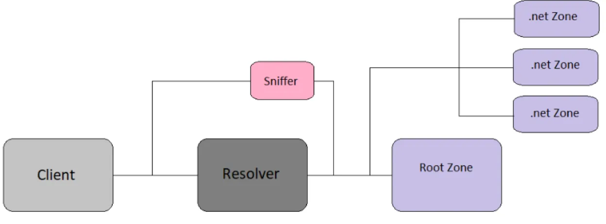
In this chapter, we will describe how we set up our test bed and how the components interact with each other. In addition, we also outline the configuration parameters of the individual components, while also describing some tools we used to analyse our data.
4.1
Overview
The testing method consists in the following steps: from a client machine, we issue a series of queries to our chosen domain (www.net.) which we have previously set up. The network traces are then captured using another machine to sniffout the network
packets, generating packet tracing (.pcap) files with the contents of the network packets of each test. After obtaining these files, we analyse them resorting to DNSJit, a tool which allows us to parse a .pcap file, loading all the attributes of a DNS message (such as the source IP address, the destination IP address, all the flags, the query itself) into an easily manipulated data structure. Next, we analyse the data structures, retrieving statistics such as the percentage of queries that were responded by each authoritative server and the latencies experienced. Finally, we re-use the latency of the queries to plot charts that associate a query with its latency.
C H A P T E R 4 . T E S T B E D
domain.
Having the fake root zone set up, we next set up three authoritative servers for the net. TLD. These authoritative servers all share the same zone file, with a slight difference
between them: The zone file itself contains one single entry, for the domain www.net. (for the sake of simplicity), which is associated with a single IP address, which is related to the authoritative server to which the zone belongs to. This leads us to have an easy way to debug and actively monitor the test, as the dig results will contain the IP address obtained, which will vary depending on which authoritative name server was contacted.
4.2
Necessary Machines
Figure 4.1: Test bed
Our test bed itself consists in seven separate machines, depicted in figure4.1, which are configured and managed through the usage of virtualisation software. All the ma-chines should have a connection to each other: i.e. any machine should be able to ping any other machine, so they can all communicate with each other. Every machine should have some way of being remotely accessed by the controller of the tests. This means that every machine will require SSH or, in the case of the Windows machine, Windows Remote.
4.2.1 Client
The client machine is running on Linux, and is in charge of overseeing the tests, in addition to retrieving the .pcap files generated by the sniffer machine and analysing them.
It is required for SSH andDNSJit[4] to be installed in this machine, as we need to access the remaining machines via SSH to control them and transfer files to the client machine. Given that we also need to communicate with Windows machines, we opted to also install python, along with its package pywinrm. Pywinrm (Python Windows Remote) allows us to remotely connect to a Windows machine without requiring us to set up SSH access on the Windows machine (although this can be done), and is then used to access the
4 . 2 . N E C E S SA RY M AC H I N E S
Windows resolver. DNSJit is required as it is the tool we have selected to analyse the .pcap files.
In our setup, we were generating the queries outside of the client machine, and then transferring them to the client. If, however, we wanted to keep everything inside the client machine, and thus more automated, we would also need to install Java on this machine, as our query generator is written in Java.
The client machine should also have the IP addresses of the resolvers as well as the authoritative name servers in its hosts file, as the test generator utilises the names to sort the tests, while it retrieving the IP addresses from the hosts file.
4.2.2 Sniffer
The sniffer machine is also running on Linux, and is in charge of collecting the network
traffic to then be processed by the client machine. Given that the purpose of this machine
is to collect the network traffic , we require a tool that does so and places it in the .pcap
format. To this end, we opted to use the widely known tcpdump command, and is thus required in this machine.
4.2.3 Authoritative Servers
There are a total of four authoritative servers and they are all running on a Linux op-erating system. One server is authoritative over the root zone, while the other three are authoritative over the .net zone, as shown in figure4.1. All these servers are set to be authoritative only via BIND options, and thus they require BIND to be installed. It should be noted that, despite BIND being installed, they do not act as resolvers. The server responsible for the root zone does not require any additional software, other than BIND. The remaining three servers, however, require a tool that can simulate delays in the network, in order to introduce latency in our tests. For that, we usetc-netem[19] to
add a qdisc (a qdisc, or queueing discipline, is a traffic control scheduler [14] manageable
through the tc linux command) to each server, which we configure to have the necessary parameters for each test.
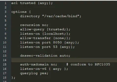
Moving on to the configuration options of the servers, which are shared between all four of them, except the definition of their zone files. These options are detailed in figure 4.2. Here, the important option, which turns the servers into authoritative only servers, is the option in line 6, signifying that we do not wish for this server to be recursive. All servers must then load their zone files, as shown in figure4.3. Here, the name of the zone as well as its file path will obviously vary, depending on which zone should be added to which server.
The root zone file is depicted in figure4.4. It is a stripped down version of the root zone file located atIANA[6], to which we added our own .net TLD. We maintained the
C H A P T E R 4 . T E S T B E D
Figure 4.2: Configuration file of authoritative servers of the root and .net domains
Figure 4.3: Configuration file where we load the root zone
lines 6, 9 and 12, this TLD has three name servers, ns1, ns2 and ns3, each associated with their A glue records.
Figure 4.4: Root zone file
The authoritative name server zone file is depicted in figure4.5. It should be noted that this is the zone file for ns1, with the zone files for ns2 and ns3 being slightly different:
after SOA, they would have ns2 and ns3, respectively, and the first record would be ns2.net. and ns3.net., respectively. As can be seen, it is quite similar to the root zone file, with the main change being the SOA record, which states that the server with this zone
4 . 3 . I N D I V I D UA L T O O L S
file is authoritative for the .net zone.
Figure 4.5: .Net zone file
4.2.4 Resolvers
Finally, we have the resolvers. Out of our four selected resolvers, three of them (Pow-erDNS, Unbound and Bind) are hosted on machines running a Linux operating system, while the remaining resolver (Windows-Server 2012) is hosted on machines running its re-spective Windows version, as the resolver itself comes bundled with the whole operating system package.
In order for the resolvers to be able to resolve our domain, we must first point them towards our own root server. This is done by replacing the standard hints file, which points to the original root servers, to ours (as seen in figure4.6), which replaces the IP address of one root server with the IP address of our own root server. In the Windows resolver, we also change its hints file, to only contain one entry, shown in figure4.7. As for the remaining configuration options, we stick to the default options. This means that our resolvers may not necessarily be as optimized as they can be, as there may be options which increase their performance.
Figure 4.6: .Net zone file
4.3
Individual Tools
In this section, we will talk about two tools that we have used, specifically, DNSJit[4]
C H A P T E R 4 . T E S T B E D
Figure 4.7: Windows root hints
4.3.1 DNSJit
DNSJit is an engine for capturing, parsing and replaying DNS messages. This tool is a combination of parts of other tools (dsc, dnscap, drool) built with a Lua wrapper, which creates a script-based engine. For our purposes, the core functionality of DNSJit consists in its ability to parse and process DNS messages, which we use to process the DNS messages and feed them to a structure that we created. Once we have the data-structure with all the information we need, we then process it, extracting statistics about the dataset.
Since DNSJit is a script-based engine, we run the files by executing the command ”dnsjit <our_file> <parameters>”. We have generated two DNSJit scripts, slightly based on the examples available on the tool’s website: one script analyses the .pcap file that we feed to the script, producing statistics, while the other script produces a graph that associates each query with the latency it experienced, in order to facilitate visualisation of the data.
These two scripts require eight parameters, separated by whitespace:
1. <.pcap file> - This parameter provides the .pcap file that will be analysed.
2. <tested_domain> - The domain to which the queries were pointed at. In our tests, this was always ”www.net.”.
3. <test_runtime> - How long the test was ran for.
4. <query_interval> - The interval between each successive query.
5. <filename> - The name of the file where the script will write its output
6. <resolver_used> - The resolver that was used for this test.
The second to last parameter varies between the two scripts. On the statistics script, this parameter is <ttl_used> - the value of the TTL that was used for this test. On the graphing script, this parameter is <resolver_ip_addr> - the address of the IP address used.
The last parameter is the list of servers that were used in this test. This list contains the IP address of the server, the latency that the server was set to during the test, the
4 . 3 . I N D I V I D UA L T O O L S
packet loss that the server was set to during the test and the shutdown interval, which is how long of an interval there should be between periods where the server is available. This parameter should be set between quotation marks, and multiples of this parameter can bet provided to the script, with each of them detailing the specifications of one server. The final command to run our scripts looks like this: dnsjit <scriptname> <.pcap file> <tested_domain> <test_runtime> <query_interval> <filename> <resolver_used> <ttl_used OR resolver_used> <”ip_address latency packetloss shutdown_interval”>
4.3.2 Query Generator
In order to generate our queries, we wrote a very simple Java-based query generator. This generator outputs a script, which is then ran on the client machine. This script will handle all the set up necessary for every test, the test itself and the collecting of data and its analysis. In order for the generator to support all these functionalities, it requires a few parameters:
1. <tcpdump_opts> - A quotes enclosed list of options for the tcpdump command, all separated by whitespace
2. <test_name> - The name of this test. We named the tests sequentially i.e. Test 1, Test 2, Test 3
3. <resolver> - The IP address resolver to be used for this test.
4. <domain> - The domain to be queried during this test.
5. <resolver_name> - The name of the resolver to be used for this test.
6. <query_filename> - The filename of the output of the query generator.
7. <results_filename> - The filename of the results of the test.
8. <ttl_used> - The TTL used for this test.
9. <next_script> - The name of the next script to be used, in order to chain several tests one after the other.
10. <query_internval> - The interval between each successive query in this test. If set to -1, it will generate a random value between 0 and 1 seconds.
![Figure 2.1: The overall structure of DNS, adapted from [2]](https://thumb-eu.123doks.com/thumbv2/123dok_br/16521635.735674/28.892.129.767.385.570/figure-overall-structure-dns-adapted.webp)
![Figure 2.2: A client’s browser requesting the IP address of www.wikipedia.org, adapted from [7]](https://thumb-eu.123doks.com/thumbv2/123dok_br/16521635.735674/29.892.137.740.327.595/figure-client-browser-requesting-ip-address-wikipedia-adapted.webp)
![Figure 3.1: Locations of more than 7,900 vantage points from RIPE Atlas, taken from [11]](https://thumb-eu.123doks.com/thumbv2/123dok_br/16521635.735674/38.892.135.759.304.658/figure-locations-vantage-points-ripe-atlas-taken.webp)