Pullout performance of steel bars partially bonded
in concrete with epoxy resin
Avaliação da aderência de barras de aço coladas
ao concreto com resina epóxi
a Universidade do Estado do Rio de Janeiro, Departamento de Estruturas e Fundações, Rio de Janeiro, RJ, Brasil; b Marinha do Brasil, Rio de Janeiro, RJ, Brasil.
Received: 05 Apr 2017 • Accepted: 16 Oct 2017 • Available Online:
R. H. SOUZA a
M. E. TAVARES a
D. V. FERNANDES b
Abstract
Resumo
The installation of new reinforcing bars onto an existing structure is a common practice in civil construction both for old and new structures. The
use of anchors has been extensively studied and normalized. The placement of steel reinforcement bars in holes filled with epoxy resin, despite
their wide use, still lacks a satisfactory methodology for the design of such systems. In this context, the aim of this paper is to present the results
of an experimental programme for confined pullout tests, comparing the performance of cast steel reinforcement bars to that of bars bonded to
concrete with epoxy resin. The investigated test parameters included the bar diameter, the embedment length and the resin thickness. Tests
re-sults showed a significant efficiency of epoxy resin as structural bonding agent and allowed the verification of sizeable reduction in the anchorage
lengths for bonded bars.
Keywords: pullout tests, bond, retrofit, epoxy resin.
A fixação de armaduras novas em estrutura existente é prática usual na construção civil, tanto em construções novas como em antigas. A aplica
-ção de chumbadores já está bastante estudada e regulamentada. A fixa-ção de barras de alta resistência em furos preenchidos com resina epóxi, apesar de amplamente utilizada, ainda não dispõe de metodologia satisfatória para o dimensionamento desses sistemas. Neste artigo apresenta
--se os resultados de um programa experimental que teve por objetivo estudar a ligação de barras coladas ao concreto com resina epóxi através
de ensaios de arrancamento, onde foram testados diferentes diâmetros de barras, de comprimentos de colagem e de espessuras de resina. Os
resultados dos ensaios mostraram a grande eficiência da resina epóxi como adesivo estrutural e permitiram verificar reduções significativas nos
comprimentos de ancoragem das armaduras coladas.
1. Introduction
Retrofit and strengthening methods applied in concrete structures
usually require the addition of new reinforcement bars. In order to guarantee the transfer of forces between the existing structure and the new reinforcement bars, these bars can be installed and
anchored to the existing element through different techniques, such as overlapping patches, by filling the holes with resin or
special grout; or even by attaching connectors (or post-installed
anchors) in holes drilled in the concrete, which can later be fixed
with grout or synthetic bonding agents.
In recent years, many researchers have studied the behaviour of bonded connections both analytically and experimentally, based
on confined and non-confined test models. In confined models, the
reaction of the loading system is placed adjacent to the anchor to ensure bond failure and avoid failure of the concrete cone. On
the other hand, in non-confined models, the point of reaction is positioned at a significant distance from the anchor and, as a
result, can allow free formation of the cone.
Studies analysing the performance of bonded anchors usually
consider models consisting of slabs in non-confined tests,
which lead to a combination of shallow concrete cone failure and bonding of the anchor-adhesive interface. These tests have
their embedment lengths wholly filled by the bonding agent. For
instance, the tests realized by McVay, Cook and Krishnamurthy
[1] in non-confined procedures considered anchors of 15.9mm
diameter (threaded rods), 19mm diameter holes and bonding lengths of 76, 102, 127, and 152mm. The results showed an average shear stress of t0=11.8MPa and maximum shear stress equivalent to tmax=13.8MPa.
In the case of retrofitting old structures, which mostly have low
concrete resistance, the capacity of the traditional anchor leads to premature rupture of the concrete cone. In order to better study
this effect, Gurbuz and Ilki [2] carried out pullout tests on fully
and partially bonded bars in confined and non-confined models, observing different rupture models. While the fully bonded anchors
went through an abrupt rupture, with rupture of the cone and the bonding, the partially bonded anchors failed pullout, after yielding of the steel. According to the results, the partially bonded anchors had a mean resistance 73% higher than that of the completely bonded anchors. These anchors failed due to yielding of the steel bars or, in the case of small bonding lengths, due to bond slipping on the bonded length. These results suggest that partially bonded anchors have better performance (ductile behaviour) for
retrofitting applications where the concrete is of low resistance and
when spaces are limited. Shear stresses for such partially bonded anchors ranged from 15.7MPa to 23.6MPa, which are higher values than those obtained by McVay, Cook and Krishnamurthy [1]. Therefore, the authors concluded that partially bonded anchors have better performance (ductile behaviour) for evaluating the
anchorage length of deformed bars used in retrofitting applications.
The authors also found that for fully or partially bonded anchors pullout performance increases with longer bonding length, although average bonding stress decreases with an increase in length. Bonded anchors have been the object of many studies and have normalised design forecasts such as the AC308 Post-installed Adhesive Anchors in Concrete Elements [3] standard. However, there is still a lack of studies on the bonding of highly resistant bars
used as additional reinforcement in retrofitting and strengthening
work. In these cases, the structural elements usually have lower resistance concrete than the current. In addition, the spaces needed for installation of these bars are very narrow.
With the objective of comparing the anchorage length of bars
bonded or otherwise into concrete, the following authors developed
confined tests, considering structure repair or retrofit.
Souza [4] carried out pullout tests in models shown in Figure 1.
Two steel diameters (8 and 12mm) and three bonding lengths (7.5, 10, 15cm) were used. An epoxy resin with 3.0mm thickness was also used. Two series of tests were carried out; these being SR models with bars embedded in concrete and CR models in which the bars were subsequently bonded with epoxy resin. The diameter of the holes corresponded to the diameter of the bars plus 6 mm. The average compressive strength of the concrete was 42MPa at the time of the test and the steel yielding strengths for 8 and 12mm bars were 500MPa and 401MPa, respectively. The test results showed that bonding performance of the connection with epoxy resin improves with longer bonding length and also with the type of connection. Anchoring with epoxy resin in d=8 mm bars allowed a reduction in length of up to 33%, whereas for d=12 mm bars, the reduction was up to 50% in regard to the anchoring lengths with no epoxy resin.
Felício [5] carried out pullout tests with deformed steel bars with
diameters of 10, 12.5, and 16mm (yielding stress of 620MPa, 600MPa
and 660MPa, respectively), as shown in Figure 2. The dimensions of the model were fixed proportionally to the diameters. Four lengths
were studied for each diameter: 5 d; 7.5 d, 10 d, and 12.5 d. The
thickness of the concrete cover was fixed as three times the diameter
of the steel bar (c/d=3). The SR models had the reinforcement bars positioned at the time of concreting; the CR models were moulded without the bars, which were later bonded with resin. The holes went through the whole bond length and the dhole/dbar ratios were 1.3 and
Figure 1
1.4 respectively. The results showed that for both models, for a given diameter, longer bonding length produced higher maximum ultimate loads, greater displacements and very close values for bond stress.
The epoxy resin was found to be a very effective structural bonding agent, with a significant reduction in anchoring lengths for bonded
bars of: 24% for bars where d=10mm; 42% for bars in which d=12.5 mm, and 29% for bars where d=16mm.
Bouazaoui et al [8] studied the interfacial shear strength between the steel bar surface and the concrete surface of steel rods that were
previously bonded with epoxy resin into concrete using confined
pullout test. The concrete specimen was a cylinder with a diameter of 160 mm and a length of 320mm. Three steel diameters (12, 16 and 20mm) and lengths from 100 to 300mm of embedded steel in the concrete were used. The adhesive thickness was 1 mm. The yield strength of the steel bar obtained through the test, was 340MPa and the concrete had an average compressive strength of 40MPa at 28 days. During the test, the specimen was subjected to a continuously increasing load until failure of the specimen was observed. The failure occurred in the three principal regions; in the concrete, at the
steel–concrete interface and on the steel rod. The author verified that the adhesive joint significantly improved the shear and tensile
stress distribution along the interface between the steel surface and the concrete surface. The ultimate force depended linearly on the diameter and the embedded length of the steel rod.
Fernandes [6] followed this line of research with the aim of contributing to the increase in scientific knowledge on the
empirical practice of civil construction, mainly used in the area of reinforcement and structural recovery. The objective of this work was to evaluate the bond capacity of reinforcement bars previously bonded to concrete structures. The laboratory tests realized and its results will be addressed in the following topics.
Figure 2
Felício’s model [5]
Figure 3
2. Materials e methods
Fernandes [6] carried out pullout tests in prismatic models as
well as bending tests on concrete beam, in order to assess the anchorage bond length of these longitudinal tensioned bars.
2.1 Beam models
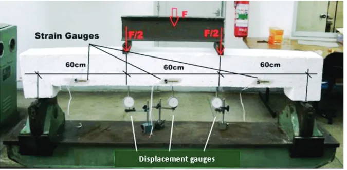
Bending tests were applied to concrete beams, with two concentrated loads, located on the third sections of the span. The beam tests aimed to analyse the bonding behaviour of the bars that
were bonded to the concrete, similarly to that occurring in retrofit or
strengthening work on existing beams. As such, two beams were cast; one in fully reinforced concrete and with a reinforcement bar traditionally anchored with hooks, named beam V1; and the other produced in two stages, with its lower bars bonded to the ends (around 20cm) with epoxy resin in pre-drilled holes in the concrete, named beam V2. The beams were 2m long, with a rectangular section of 20cm in height and 20cm wide.
Beam V2 was cast in two concreting stages. In the 1st stage its height was only 13cm and rubber tubes were installed in the region of the supports in order to guarantee the presence of holes, which were essential for the later bonding process of the longitudinal bars. The anchorage length of these bars corresponded to the entire length of the support, i.e., the bars were bonded over a 20cm length. Moreover, the stirrups were exposed for future bending and fastening on the lower part of the beam (where it received 6cm of supplementary concrete cast after the installation of the
longitudinal bars). See Figure 3.
The longitudinal bars from V2 were glued as soon as the beam
was detached from the mould. First the holes were cleaned, all
the powder and dust being removed, then the epoxy resin was applied inside the hole and soon after the reinforcement was
inserted into holes, these being abundantly embedded in resin
in order to guarantee complete filling of the hole with the resin.
After a four-day curing period, the concrete surface in the region to be completed was cut to improve the bond between the two
concrete layers. From this, the stirrups were bent and fastened
and the bottom of the beam was soaked, in preparation the second stage of concreting. The concrete of the 2nd stage was the same strength and granulometry.
Figure 4 shows the test loading apparatus and the devices used to
evaluate the stress, strain and displacement.
2.2 Prismatic models
The pullout test adopted was that normalized by RILEM [7]. This test has simple execution characteristics and was adapted to the study to allow bonding with epoxy resin. In order to do so, 61 pullout tests were conducted. Highly resistant steel bars were embedded in concrete cubes, during concreting, named non-resin models (SR) or embedded afterwards, bonded with epoxy resin, as resin bonded models (CR).
In order to compare models with different reinforcement bars, its
dimensions and the embedded length were adjusted proportionally to the bar diameters. Three bar diameters were tested: 10mm; 12.5mm and 16mm, along with two embedded lengths for each diameter: 5 d and 7.5 d. The results refer to the average result obtained from the three sample tests. Their dimensions varied according to the bar diameter for both pre-bonded and post-bonded bars, in the proportion of 10d. Three thickness levels for epoxy resin were tested: 1mm (CR1), 2mm (CR2), and 3mm (CR3).
Identification of the models is shown in Table 1 and follows the
example of: model 10-7.5-2, which corresponds to the 10mm diameter bar, with an embedded length of 7.5 d and a 2mm resin thickness.
Figure 4
Plastic tubes were embedded in the concrete models to minimize
the negative effects of drilling and to serve as a template for the
holes the steel bars would pass through. Concrete was then applied to the models that would receive the bonded bars. These plastic tubes had the exact diameter predicted for each model, that is, the space of the hole included the diameter of the bar plus the thickness the epoxy resin would take. Concrete was manually placed into the formworks, layer by layer, perpendicularly to the reinforcement, as
showed in Figure 5. After the placement of each layer an immersion vibrator was used and the specimen was finished with a trowel.
Afterwards, these tubes were removed and all holes and bars
were cleaned to remove dust and any impurity that could affect
the bonding process. In the region where a non-bond length was
desired, the bar was wrapped with PVC film and finished with
an insulating tape plug, so as to prevent resin draining from the adherent region to the non-adherent region.
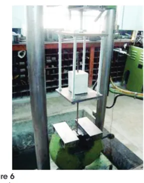
The goal of the test was therefore to allow the application of a tension load at one end of the bar and to measure the relative displacement between the bar and the concrete at the other
end. For this, a metal cage was used in order to react against
Table 1
Pullout tests results
Model
Embedded lenght l (mm)
Hole’s diameter
do (mm)
Bond surface (cm2)
Ultimate load (kN)
Bond stress tb (MPa)
Increase of capacity tb.CR / tb.SR
10-5-0 50 – 15.7 12.2 7.8 –
10-7.5-0 75 – 23.6 34.4 14.6 –
12.5-5-0 62.5 – 24.5 24.4 9.9 –
12.5-7.5-0 93.8 – 36.8 51.8 14.1 –
16-5-0 80 – 40.2 53.2 13.2 –
16-7.5-0 120 – 60.3 77.8 12.9 –
10-5-1 50 12 15.7 48.8 31.1 4.0
10-7.5-1 75 12 23.6 54.8 23.3 1.6
12.5-5-1 62.5 14.5 24.5 68.0 27.7 2.8
16-5-1 80 18 40.2 90.4 22.5 1.7
16-7.5-1 120 18 60.3 123.0 20.4 1.6
10-5-2 50 14 15.7 48.8 31.1 4.0
10-7.5-2 75 14 23.6 52.6 22.3 1.5
12.5-5-2 62.5 16.5 24.5 69.8 28.4 2.9
12.5-7.5-2 93.8 16.5 36.8 90.6 24.6 1.8
16-5-2 80 18 40.2 101.4 25.2 1.9
16-5-3 80 22 40.2 117.2 29.2 2.2
16-7.5-3 120 22 60.3 83.8 13.9 1.1
Figure 5
the concrete block whilst the other free end was subjected to the
tension, as shown in Figures 6 and 7.
2.3 Materials
The concrete was mixed with the intention of replicating the characteristics of reinforced concrete constructions at an age in need of both retrofitting and structural intervention. Thus, the mean resistance to concrete compression during the tests was 26.9MPa. The yielding and the maximum strength of the steel were 603MPa and 742MPa for the 10mm bar, 584MPa and 735MPa for the 12.5mm bar, and 564MPa and 714MPa for the 16mm bars. The choice of epoxy resin currently used in civil construction took into consideration the characteristics of fluidity, handling and material accessibility. In order to check the resin’s performance according to the conditions presented
in this study, two systems were evaluated. Firstly, the RE 500
Hilti system was tested but its thixotropic characteristic proved to be unfavourable to the passage of the bar through the hole.
Sikadur 32 was then tested and the results were suitable and it was therefore applied according to the manufacturer’s instructions.
3. Results
3.1 Test beam results
The V1 beam failed at the concrete compression zone and
presented excessive deformation of the bar under tension. Failure
of the V2 beam occurred along the diagonal concrete compression strut. The cracks produced by bending demonstrated symmetrical behaviour in relation to the span and as expected, no shear cracks were seen due to the detailing of the reinforcement bars.
The V2 beam did not show any bond cracking at the interface of the two concrete layers indicating that both the concrete-concrete bond
and the bonding of steel bars in the concrete were efficient. The epoxy resin efficiently complied with its adhesive characteristics,
ensuring anchorage of the longitudinal tension bars.
Figure 6
Test setup
Figure 7
Displacement device
Figure 8
The behaviour of both beams was similar as shown in Figure 9.
3.2 Pullout results
The non-resin models failed pullout, characterized by the slipping
of the bar in relation to the concrete, with significant displacements.
The resin models presented brittle failure, characterized by the sudden rupture of the concrete block and small relative displacements between the bar and the concrete as presented in
Figure 10. In one of these models, the steel bar yielded. Some
specimens showed air bubbles in the bonded length leading, in these cases, to pullout failure.
The typical curves of the SR and CR models are presented in
Figures 11a to 11d; these graphs also show the homogeneity of
the results, which are summarised in Table 1.
Figure 9
Load-displacement relationships at midspan
of beams
Figure 10
Brittle failure in CR models
Figure 11a
Load-slip, models SR 10-7.5-0
Figure 11b
4. Discussion
The influence of the embedded length can be seen in the graphs of Figures 12 and 13, where for the same bar diameter, the increase
in embedded length led to higher adhesion strength and ultimate
load values in all models studied.
In the same way, the influence of the bar diameter can be seen in the graphs of Figures 14 and 15, where for the same embedded
length, the larger the diameter of the bar, the higher the values of adhesive strength and ultimate load in all models studied.
These results can easily be perceived through examination of the
Figure 11c
Load- slip, models CR 12.5-7.5-2
Figure 11d
Load- slip, models CR 16-5-3
Figure 12
Influence of the embedded length, models:
12.5-5-0 and 12.5-7.5-0
Figure 13
Influence of the embedded length, models:
12.5-5-2 and 12.5-7.5-2
Figure 14
Influence of the bar diameter, models:
10-7.5-0; 12.5-7.5-0 and 16-7.5-0
Figure 15
bonding surface, that is, the bar-concrete or bar-resin-concrete
contact surface. Figure 16, which reports the maximum load to
the bonding surface indicates that when the bonding surface is increased (diameter and embedded length) the pullout bearing
capacity is also increased. This has also been observed by Gurbuz [2], Souza [4], Felício [5] and Bouazaoui et al [8].
Figures 17-19 illustrate the behaviour of some models. These graphs show that bonding with epoxy resin increases the stiffness
of the steel-concrete bond and leads to higher ultimate load values. Bonding with epoxy resin also provides an increase in bond stress, as can be seen in the Increase of Capacity column in Table 1 and
in the graph of Figure 20. On this graph it can be observed that the
resin models have higher values for bond stress when compared to those without resin. Also, the values for this stress decrease as the bar diameter and the embedded length are increased. These results appear to indicate that, when using epoxy resin connections, small lengths are enough to ensure bonding and
Figure 16
Load-Bond Surface, SR and CR models
Figure 18
Load - slips, models: 12.5-5-0;
12.5-5-1; 12.5-5-2
Figure 19
Load- slips, models: 16-7.5-0; 16-7.5-1; 16-7.5-2;
16-7.5-3
Figure 17
longer lengths may not contribute to the development of stresses throughout the embedded length. This has also been observed by
Gurbuz [2]. The values for shear stress found in Fernandes’ [6]
tests ranged from 16 to 29 MPa, which is a range compatible with
the values found by Gurbuz [2].
In the graphs of Figures 15 and 20, which compares the
performances of the resin and non-resin models for thicknesses of 1 and 2mm, it is found that the variation in resin thickness does not
significantly affect ultimate bond strength.
With the aim of verifying the efficiency of the bonding process, the graphs presented in Figures 21-23 were plotted to relate the
values for maximum normal stress in the reinforcement bars with
the value of l /d. These normal bars stresses refer to Fmáx /d, in
the case of the models without resin, whereas Fmáx /do applies to models with resin. Considering the value of 500MPa for the yielding strength for CA50 steel and based on the equations for linear regression there is a 67% reduction for 10mm bars, 51% for 12.5mm, and 20% for 16mm bars.
5. Conclusions
Based on the bond method, the materials used and the test
methodology adopted in this study, the authors concluded that:
n The share of adhesion is highly significant in CR models; in
these cases, the slips for initial and mean loads were extremely low when compared to the SR models.
n Regarding the failure mode, all SR models failed pullout.
Specifically, for CR models the concrete failure was brittle,
considering the weakest link in the bond.
n In all models - with and without resin - the increase of both the bar diameter and the embedded length led to higher values of adhesion force and ultimate load.
n Bonding with epoxy resin allows a reduction in the anchoring
lengths of the bars.
n The beams demonstrated significantly similar behaviour, in
spite of their reinforcement details being quite different. This reaffirms the efficiency in the bonding of the bars, aimed at
reducing the anchorage length required.
n Variation in thickness of the epoxy resin from 1mm to 3mm
seems to have no significant effect on the failure, but requires
further study to assess its service behaviour.
n The development of further research is suggested with the aim
of evaluating the anchoring length of epoxy resin bonded bars
in concrete elements subjected to different stresses.
Figure 22
Bar Tensile Stress - l /d relationships, d=12.5mm
Figure 23
Bar Tensile Stress - l /d relationships, d=16mm
Figure 20
Bond Stress-Bond Surface, SR and CR models
Figure 21
6. Acknowledgements
This research was conducted at Rio de Janeiro State University -
UERJ (Brazil). Support provided by UERJ, CAPES and FAPERJ
is gratefully acknowledged. The authors also extend their thanks to Hilti Brazil.
7. References
[1] McVay, M.; Cook, R. A.; and Krishnamurthy, K.. Pullout Simulation of Postinstalled Chemically Bonded Anchors. Journal of Structural Engineering, ASCE, V. 122, No. 9, Sept. 1996, pp. 1016-1024.
[2] Gurbuz, T.; Ilki, A.. Pullout Performance of Fully and Partially Bonded Retrofit Anchors in Low-Strength Concrete. ACI
Structural Journal, V. 108, nº1 (2011), pp. 61-70.
[3] ICC International Code Council. AC308 Post-installed Adhesive Anchors in Concrete Elements, USA, 2014. http:// www.icc-es.org/.
[4] Souza, R. H.F. Análise do comportamento de vigas de betão armado reforçadas à flexão e ao esforço transverso, Lisboa, 1990, Tese (doutorado), Instituto Superior Técnico, 320p. [5] Felício, M. D. Eficiência da Ligação Aço-Concreto Utilizando
Colagem com Resina Epóxi. Rio de Janeiro, 1995, Dissertação (mestrado), Universidade Federal Fluminense,
159p.
[6] Fernandes, D.V..Estudo da aderência de barras de aço coladas ao concreto com resina epóxi. Rio de Janeiro, 2011, Dissertação (mestrado), Universidade do Estado do Rio de
Janeiro, 160p.
[7] RILEM, FIP, CEB, 1973, Essai portant sur l’adhérence des armatures du béton. 1. Essai par flexion (7-II-28D). 2.
Essai par tration (7-II-128), Recomamdations Provisoires.
Matériaux et Constructions, (mars – avr), v. 6, n. 32, pp.
96–105.