Universidade do Minho
Escola de Engenharia
Tiago Emanuel Oliveira Gomes
Universidade do Minho
Escola de Engenharia
Tiago Emanuel Oliveira Gomes
3D Virtual Environments' Generation
Dissertação de Mestrado
Mestrado em Engenharia Informática
Trabalho realizado sob orientação de
Professor Doutor José Creissac Campos
Doutor José Luís Cardoso da Silva
DECLARAÇÃO
Nome
Tiago Emanuel Oliveira Gomes
Endereço Electrónico
Número do Cartão de Cidadão
13615192
Título da Dissertação
3D Virtual Environments’ Generation
Orientador
Professor Doutor José Creissac Campos
Co-orientador
Doutor José Luís Cardoso da Silva
Ano de Conclusão
2013
Designação do Mestrado
Mestrado em Engenharia Informática
É AUTORIZADA A REPRODUÇÃO INTEGRAL DESTE TRABALHO APE-NAS PARA EFEITOS DE INVESTIGAÇÃO, MEDIANTE DECLARAÇÃO ES-CRITA DO INTERESSADO, QUE A TAL SE COMPROMETE.
Universidade do Minho, / /
Acknowledgements
I would like to dedicate this work to my family who were always present during my academic path and specially to my girlfriend Isabel Correia who was always ready to help and to give support.
I would like to give special thanks to my supervisors for all the advice, support, patience and availability throughout the dissertation. Particularly to José Creissac Campos for the expert guidance and to José Luís Silva for helping me to understand the APEX framework. Many thanks to Tiago Abade for his friendship and total availability during my passage through the University and specially during the course of this dissertation. Big thanks to Isabel Correia for recording the voices for the Asthma Game, and for the love, patience and encouragement during the dissertation. It would not be possible without her. Thanks to all of my friends for causing the good disposition required to carry out this work.
I would like to thank the Fundação para a Ciência e Tecnologia for their finan-cial support.
Finally, I would like to thank my family for being my motivation. Thanks to my brothers for the comprehension and help. Thanks to my parents for the advice, for guiding me through my education, and also for the support needed to all of these years of study. And thanks one more time to Isabel Correia for being always present and for being my guiding star.
To all these people, I want to give my deepest gratitude. This work would not be completed, if it were not for them.
This work is funded by ERDF - European Regional Development Fund through the COMPETE Programme (operational programme for competitiveness) and by National Funds through the FCT - Fundação para a Ciência e a Tecnologia (Por-tuguese Foundation for Science and Technology) within project FCOMP-01-0124-FEDER-015095.
Abstract
3D Virtual Environments’ Generation
The development and testing of ubiquitous environments (places enhanced with sensors, public displays and personal devices) usually presents high costs, both due to the need to acquire specific hardware (sensors, displays, etc.), and the need to use, or even to build, a space wherein the physical system will be implemented. Consider, for example, the impact of testing a new ambient intelligence system to provide information in a hospital or in an airport. It is hardly feasible trying to prototype the system in the target environment due to the costs (e.g. of redesign) and problems associated with such approach. The use of three-dimensional virtual environments then arises as a solution to this problem. Using them, it becomes possible to simulate the use of technology without needing to purchase hardware, and without interfering with the physical environments in which the final system will be installed.
Three-dimensional application servers such as SecondLife (secondlife.com) or OpenSimulator (opensimulator.org) provide an easy way to develop virtual worlds. A platform for the prototyping of ubiquitous environments is being developed at the Department of Informatics of the University of Minho, which is based on OpenSimulator: the APEX (rApid Prototyping for user EXperience) framework. At the moment, each new world has to be modelled manually, using an OpenSim-ulator compatible viewer, which makes this part of the process time-consuming and inefficient.
This project’s objective is to study three-dimensional virtual environment mod-elling approaches, and to develop a module that integrates one of these approaches in the APEX framework to streamline the virtual worlds generation process. The tool developed is presented in this dissertation. It has reduced significantly the environment generation development time in the APEX framework. Moreover, a case study was developed during the project where the tool was used to build the environment. Despite the tool has been developed to meet the needs of the APEX platform, it can be quite useful for other OpenSimulator users.
Resumo
Geração de Ambientes Virtuais 3D
O desenvolvimento e teste de ambientes ubíquos (locais enriquecidos com sen-sores, ecrãs públicos e dispositivos pessoais) está normalmente associado a cus-tos elevados, quer seja pela necessidade de adquirir hardware específico (sensores, ecrãs, etc.), ou mesmo pela necessidade de usar, ou até construir um espaço onde o sistema ubíquo será implementado. Considere, por exemplo, o impacto de testar um sistema inteligente de informação num hospital ou num aeroporto. É imprat-icável tentar prototipar o sistema no local destinado, devido aos custos (p.e. de redesenho) e dificuldades associadas. O uso de ambientes virtuais tridimensionais aparece como uma solução para este problema. Utilizando este tipo de mecanis-mos, torna-se possível simular a instalação da tecnologia sem que seja necessário adquirir o hardware e sem interferir com o espaço físico onde o sistema final será instalado.
Os servidores aplicacionais 3D como o SecondLife (secondlife.com) ou o
Open-Simulator (opensimulator.org) proporcionam uma forma relativamente fácil de
desenvolver mundos virtuais. Está a ser desenvolvida no Departamento de Infor-mática da Universidade do Minho uma plataforma de prototipagem de ambientes ubíquos, chamada APEX (rApid Prototyping for user EXperience) que se baseia no servidor aplicacional OpenSimulator. De momento, cada novo ambiente virtual tem de ser modelado manualmente, usando um viewer compatível com o
Open-Simulator, o que torna o processo demorado e pouco eficiente.
O objectivo deste projecto é estudar soluções para a modelação de ambientes virtuais tridimensionais, e desenvolver um módulo que integre uma dessas soluções na plataforma APEX. A ferramenta desenvolvida é apresentada nesta dissertação. A ferramenta tem vindo a reduzir significativamente os tempos de desenvolvimento dos ambientes virtuais na platforma APEX. Para além disso foi desenvolvido um caso de estudo onde o módulo foi utilizado para gerar o ambiente. Apesar da ferramenta ter sido desenvolvida para responder às necessidades da plataforma APEX, ela pode ser bastante útil para outros utilizadores do OpenSimulator.
Contents
Acknowledgements v
Abstract ix
Resumo xi
Contents xiii
List of Figures xvii
List of Tables xviii
List of Abbreviations xix
1 Introduction 1 1.1 Context . . . 1 1.2 Objectives . . . 2 1.3 Structure of document . . . 4 2 Ubicomp Prototyping 5 2.1 Introduction . . . 5 2.2 APEX . . . 6 2.3 OpenSimulator . . . 7
2.3.1 Region Modules and OpenSimulator API . . . 8
2.3.2 Environment generation problems . . . 10
3 Developing Virtual Environments 14
3.1 Introduction . . . 14
3.2 OpenSimulator Archives (OARs) . . . 14
3.3 Virtual environment modelling languages . . . 17
3.3.1 Scene graphs based languages . . . 18
3.3.2 Procedural modelling . . . 20 3.4 3D modelling tools . . . 22 3.4.1 Blender . . . 23 3.4.2 MeshLab . . . 24 3.4.3 Sweet Home 3D . . . 26 3.5 Discussion . . . 28 3.6 Conclusions . . . 30
4 Virtual environment development tool 32 4.1 Introduction . . . 32
4.2 Using 3D Modelling tools . . . 34
4.2.1 Modelling the Building in SH3D . . . 35
4.2.2 SH3D and Blender . . . 36
4.2.3 SH3D and MeshLab . . . 38
4.3 Using OpenSim API . . . 39
4.3.1 The Region Module . . . 41
4.3.2 The User Interface . . . 44
4.3.3 Modelling the Building . . . 46
4.4 Conclusions . . . 47
5 Integrating the tool with APEX framework 50 5.1 Introduction . . . 50
5.2 Architecture . . . 51
5.2.1 Remote Access . . . 51
5.2.2 Multi-user . . . 54
5.3 Summary . . . 56
6 Developing serious games with APEX framework 58 6.1 Introduction . . . 58
6.2 Asthma . . . 59
6.3 The Virtual Environment . . . 60
6.4 The game . . . 61
6.5 Evaluation . . . 64
6.5.1 The user study . . . 65
6.5.2 Results . . . 66
6.6 Game redesign . . . 68
6.7 Conclusions . . . 70
7 Conclusions and future work 72 7.1 Overall analysis . . . 72
7.2 Results . . . 75
7.3 Future Work . . . 77
Appendices 79 A.1 Questionnaire . . . 79
A.2 Questionnaire results . . . 82
List of Figures
2.1 Logical architecture of the execution environments in APEX
frame-work (from [Sil12]) . . . 7
2.2 Environment generation through a viewer (basic box) . . . 11
2.3 Creating a wall with a window with 4 primitives . . . 12
3.1 OpenSim Archives internal format . . . 15
3.2 Scene graph example of a house . . . 18
3.3 Procedural building phases . . . 21
3.4 Manipulating 3D meshes with Blender . . . 24
3.5 MeshLab in action [CCR08] . . . 25
3.6 Sweet Home 3D interface . . . 27
4.1 Building model blueprint . . . 33
4.2 Using 3D modelling tools approach . . . 34
4.3 SH3D Building development . . . 35
4.4 Using Blender to transform the building model . . . 36
4.5 Result for the solution SH3D+Blender . . . 37
4.6 Using MeshLab to transform the building model . . . 38
4.7 Result for the solution SH3D+MeshLab . . . 39
4.8 Using OpenSim API approach . . . 40
4.9 Triangle representation for angle calculus . . . 43
4.10 OpenSim API approach interface . . . 45
4.11 OpenSim API approach resulting model . . . 47
4.12 Solution experience time results . . . 48
5.2 Environment generator connection panel . . . 55
5.3 Multi-user architecture . . . 56
5.4 Complete solution sequence diagram . . . 57
6.1 Mites in our homes . . . 60
6.2 House of the asthma game . . . 61
6.3 Pets in the bedroom . . . 62
6.4 Question about dirty clothes . . . 63
6.5 Survey results . . . 66
6.6 Utility section results . . . 67
List of Tables
List of Abbreviations
2D two-dimensional
3D three-dimensional
API Application Programming Interface
APEX rApid Prototyping for user EXperience
COLLADA COLLAborative Design Activity CPN Coloured Petri Nets
DAE Digital asset exchange
DB Data Base
DCC Digital content creation
DLL Dynamic Link Library
GNU GPL GNU General Public License
GUI Graphical User Interface
IP Internet Protocol
LSL Linden Scripting Language
L-System Lindenmayer System
OAR OpenSimulator region ARchive
OBJ Wavefront OBJ
OpenGL Open Graphics Library
UML Unified Modelling Language
VE Virtual Environment
VR Virtual Reality
VRML Virtual Reality Modelling Language
WWW World Wide Web
X3D eXtensible 3D Graphics
Chapter 1
Introduction
1.1
Context
The rApid Prototyping for user EXperience (APEX) framework [SORF+10] was
developed for prototyping ubiquitous computing environments. The framework uses a three-dimensional (3D) application server to provide a virtual environment were the envisaged ubicomp environment can be experienced, the OpenSimulator1.
Typically OpenSimulator virtual environments are designed using the viewer tools also used to navigate the worlds. However, the experience of using the framework shows that the step of designing the virtual environment using this approach is a slow and laborious one.
When simulating real spaces enhanced with ubiquitous systems through vir-tual reality applications, such as SecondLife2 or OpenSimulator, the creation and
design of the environment itself is one of the most time consuming and demanding processes that developers have to face. This is because the contents in it have to meet high levels of quality (e.g. in terms of detail) in order to lead the user into a pleasant and realistic experience where real world objects can be easily recognised both by its appearance and behaviour. If, for example, the user cannot recog-nise a place in a virtual world where a ubiquitous system is being tested, results of the prototyping process will never be as reliable as they should be. Also, the
1http://opensimulator.org/ (August 2013) 2https://www.secondlife.com/ (June 2013)
most frequently used techniques for describing the virtual world are very low level (e.g. Open Graphics Library (OpenGL)) which means that the developer may have to gather large amounts of information in order to provide reasonable input. Thus, the process becomes slow and the virtual world requires great effort to be developed.
1.2
Objectives
The main objective of this project is to build a component for the APEX frame-work that makes it able to use a modern and agile technique to develop virtual reality environments. An alternative to achieve this objective is to load 3D models into the virtual environment, another alternative is to use the application server Application Programming Interface (API) to build the virtual objects. So, mod-elling techniques and existent markup languages that can be used for developing virtual worlds must be studied. Also, some existent tools that already use those techniques are going to be analysed. The chosen technique must be powerful and accurate enough to meet the needs of developing 3D virtual environments which can be used for implementing and testing ubiquitous computing environments. However, it must also be abstract enough to avoid the problems that are inherent to low-level languages, like having too many lines of code or having to program how the virtual scene is organised, and to streamline the process of designing the environment. Another important aspect is that APEX users need to build the environment incrementally, which means that it must be possible to add, remove or change objects in the virtual environment during its development.
An OpenSimulator server provides two main ways of loading virtual objects or 3D models into the environment: one of them is loading an OpenSimulator region ARchive (OAR) (see Section 3.2 for a detailed description of OARs) into the server, and the other one is loading a COLLAborative Design Activity (COLLADA) model into the server. COLLADA3is an XML based schema that can be used for
exchang-ing 3D models between interactive 3D applications (see Section 3.3). Moreover, there is also the possibility of developing virtual objects through the
ulator API. This possibility can, in principle, be used to develop very efficient solutions, but it requires good knowledge about the application server API, which must be thoroughly studied.
Thus, there are three initial possibilities for solving the virtual environment generation problem in the APEX framework:
• Choose the most appropriate modelling tool and generate an OpenSimulator region ARchive (OAR). The input received from the modelling software must be structured in an adequate tool in order to generate the OAR. This solution can be very powerful, however the generation of the OAR can be quite complex due to the transformations that generating the archive might imply. Also, useful features inherent to the chosen language can be lost when converting it to generate the OAR file due to incompatibilities. This solution may improve the compatibility and sharing of the the generated 3D models between OpenSimulator versions, since they are based on an OpenSimulator native file format, however the generated models may not be as accurate as they have to, due to the conversions made.
• Generate a COLLADA model from the input received from the chosen mod-elling tool. This solution can ease the sharing of the virtual objects created because COLLADA is already a standard. However, COLLADA files have a quite complex syntax, and its components are not always compatible with other languages.
• Create a friendly interface to interact directly with the OpenSimulator Ap-plication Programming Interface (API). The OpenSimulator API is consid-erably large. It has several capacities that are not useful for a typical APEX user and would only introduce noise and make the tool more complex. The research must be focused in the relevant features. An interface like this, can be hard to implement, because it will imply developing a communica-tion layer, since the API is local to the applicacommunica-tion server and the APEX framework is most often used in a remote context.
1.3 Structure of document
In this chapter, the problem and the objectives of this project were presented and briefly discussed. In the next chapters, the APEX framework and some virtual environment modelling techniques will be described as well as the conclusions and future work of this research. The dissertation document is structured as follows:
• Chapter 2 - Ubicomp Prototyping: describes the current state of the art, in-cluding the APEX framework and its virtual environment component which is composed of an OpenSimulator application server and a compatible viewer. • Chapter 3 - Developing Virtual Environments: describes some alternatives to generate virtual environments in the APEX framework. OpenSimulator region ARchives (OARs), some important virtual environment modelling languages, as well as relevant 3D modelling tools, are described in this chap-ter.
• Chapter 4 - Virtual environment development tools: analyses the use of the tools and technologies presented in the previous chapter in order to provide solutions for the APEX framework virtual environment generation problem. At the end of the chapter the most suitable solution is chosen.
• Chapter 5 - Integrating the tool with APEX framework: in this chapter the integration of the previously chosen solution for the virtual environment generation problem with the APEX framework is described.
• Chapter 6 - Developing serious games with the APEX framework: describes the development and test of a serious game in the APEX framework. The costs of developing the virtual environment will be analysed too.
• Chapter 7 - Conclusions and future work: analyses the solutions found re-garding the objectives defined for this research. Additionally, it presents some conclusions and proposals for future work.
Chapter 2
Ubicomp Prototyping
2.1
Introduction
Building ubiquitous environments has proven to be a tricky task, which involves problems, such as environment testing, redesigning or hardware costs. While build-ing a ubiquitous environment, every decision must be well supported by previous studies, otherwise the project costs will grow very quickly. Moreover, decisions that have already been taken can be difficult to change, given that the costs in-volved in the redesign process can be very high. Also, the testing process of each new configuration can consume too much time.
Ideally we should be able to try every configuration before building the real system. In a virtual environment, real spaces can be pictured with acceptable precision. Furthermore changing decisions while developing the ubiquitous system involves much less effort than in the real world. 3D application servers play an important role in this issue. These tools provide a simple way to install and explore virtual environments with very low investment and with an acceptable quality. Thus design errors can be easily detected in the early stages of the project, and changed before deployment. In the next section, the APEX framework and its components will be presented. It uses a 3D application server to manage virtual worlds and its objective is to prototype ubicomp environments.
2.2 APEX
It was already said that ubiquitous environments’ development often presents high costs and that prototyping such environments can introduce an effective way to avoid unnecessary efforts. This way, we can test those environments before their development and consequently, we can also prevent major errors or unnecessary costs. The APEX platform arises as a framework that supports the prototyping of ubiquitous environments [Sil12]. The framework goals are to help the rapid creation of virtual environments that mimic an environment and the ubiquitous computing technology within it. APEX’s architecture consists of four main com-ponents (Figure 2.1):
• The virtual environment component that contains a 3D application server and a viewer in it. This component is responsible for the virtual environ-ment. It allows the user to navigate trough the virtual world and sends information about user’s actions and position. The application server cho-sen was OpenSimulator. It provides ways to create and manage the virtual environment. See Section 2.3 for more information about OpenSimulator. • The behavioural component is responsible for managing the behaviour of the
prototype. It sends responses to the user actions based on a Coloured Petri Nets (CPN) model, where the prototype behaviour is described. This com-ponent uses CPN Tools1 to support the management of behavioural models.
The model keeps the modelled objects’ state, so that the behavioural aspects of the objects can be kept independently from the virtual environment. • The physical component is the one that manages connections with external
devices. These devices can be smart phones, sensors or control pads for example. External devices can interact with APEX framework through this component, they can be used, for example, to move the avatar or to notify the user of the avatar state.
• The communication/execution component is a C# module that is responsible for loading the ubiquitous environment into the virtual world and for
Figure 2.1: Logical architecture of the execution environments in APEX frame-work (from [Sil12])
aging the exchange of information between the three other components cited before. Information about user actions is sent from the virtual environment to the behavioural models or physical devices through the communication component. Also, relevant information about behavioural models or physical devices state is sent to the virtual environment through this component.
2.3
OpenSimulator
OpenSimulator is a well known 3D application server. It can be used to create virtual environments to simulate scenarios of the real world. It is an open source project and is available for download on its website for the most frequently used platforms. It has the capability of being executed locally, so developers can easily customise it.
OpenSimulator can be accessed from a large set of client applications (viewers) that allow, as well, virtual environment manipulation through a Graphical User Interface (GUI). Viewers are the native tools for virtual environments creation
on OpenSimulator. Viewers support the rendering task so that users can interact with the 3D application.
An OpenSimulator virtual world is structured in regions. Each region can be accessed and managed independently. Not only 3D structures, but also sounds, can be loaded into a region. Moreover, an entire region can be loaded from a single file called an OAR. This constitutes an easy way of sharing regions. For more information about OARs see Section 3.2.
OpenSimulator provides an API to interact with external applications. This is how the APEX components interact with it.
2.3.1
Region Modules and OpenSimulator API
The other APEX framework components interact with the OpenSimulator server instance running in the virtual environment component through region modules. Modules are basically .NET Dynamic Link Librarys (DLLs) that are loaded when the OpenSimulator server is started. The OpenSimulator ”bin” directory is scanned for DLLs on every initialisation in an attempt to find region modules stored there and load them to the current 3D application server instance.
Typically, region modules drive their execution by registering for events in the OpenSimulator instance (e.g. user logins, user movement, chat messages or even clock ticks). After catching an event the module executes whatever is needed to complete its task.
Currently, there are two different types of region modules: non-shared modules and shared modules. Shared modules are the most general and control the execu-tion of all regions in an OpenSimulator instance. Non-shared modules are more specific and only control the execution for one of the regions in an OpenSimulator instance.
Region modules have a base interface that needs to be implemented for them to execute with no errors. A region module must implement INonSharedRegion-Module or ISharedRegionINonSharedRegion-Module for non-shared and shared modules respectively. Both of them extend IRegionModuleBase which is the base interface for any region module. The methods in this interface are listed and described below:
string Name { get; }
• ReplaceableInterface - This method provides stub functionality to region modules. This means that if no other region module implementing this interface is found then this method defines the default behaviour.
Type ReplaceableInterface { get; }
• Initialise - This method is called right after the module finishes loading into the OpenSimulator instance. All configurations required for the region mod-ule to run correctly, may be set inside this method.
void Initialise(IConfigSource source);
• AddRegion - This method is called when a region is added to the module. If the module is a shared one this method would be called for every region in the instance, but if the module is non-shared it will be called only once. The reference for a region scene must be set in this method so that it can be used later on the execution of the module.
void AddRegion(Scene scene);
• RegionLoaded - This method is called when all the registered modules for a determined region finished loading. The difference between ”AddRegion” method is that here we have all the functionality provided by the modules that were already loaded.
void RegionLoaded(Scene scene);
• RemoveRegion - This method is called for any removed region. This can happen either by removing a specific region manually or in a module, or by shutting the server down where all the current regions are automatically removed.
• Close - The close method is called whenever the OpenSimulator server in-stance is shut down.
void Close();
Moreover shared region modules have to implement one more method called ”PostInItialise” that is invoked when all the regions for a server instance have finished loading. So it is called on each new region. It provides the opportunity to configure the module settings every time a new region is added to the current instance of the OpenSimulator server.
There are several other methods in the OpenSimulator API. It is possible to achieve almost everything that can be done with server commands or with an OpenSimulator compatible viewer. Here we are particularly concerned with the methods and classes used to generate 3D objects in the virtual environment. The main class for 3D object creation is called ”SceneObjectGroup”. This class represents a group of linked objects. It provides several methods for the object manipulation tasks such as scaling, rotating and positioning. Another important method is implemented in the ”Scene” class and it is called ”AddNewSceneObject”. This method is used to make some instance of ”SceneObjectGroup” visible in the respective scene of a region. Also we can choose whether to persist or not, in the OpenSimulator Data Base (DB), the object we are adding to the scene. If an object is persisted, then it will be always visible in the region until it is deleted even if the server is shut down or breaks. If the object is not persisted, then it will disappear every time the server goes down.
2.3.2
Environment generation problems
As it was said, 3D application servers like OpenSimulator can help to reduce the costs associated with the prototyping of ubiquitous environments. However, the virtual world development process associated with these tools is not as evolved as it could be. It is very slow and inefficient when compared to other virtual envi-ronment areas like the games’ industry, which is constantly evolving and making use of the most powerful techniques. Rule based or graph oriented modelling are
examples of such techniques. There are several tools using these techniques to build 3D models. Some of them are going to be covered in the next chapter.
The current tool used to develop virtual environments in the APEX framework is an OpenSimulator compatible viewer. The process of creating objects through the viewer is quite abstract allowing the user to create almost any imaginable scenario. However this makes the tool little efficient when trying to develop specific environments.
The environment generation process using an OpenSimulator compatible viewer is made by creating simple primitives (prims). A prim is the smallest part of a structure in the virtual environment, and so, the most abstract too. It can be a box, cylinder, prism, sphere, torus, tube, ring, cone or a pyramid. Each prim can be mapped with a texture.
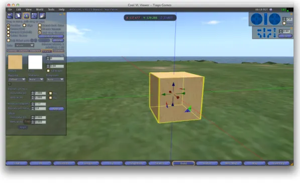
Figure 2.2: Environment generation through a viewer (basic box)
Creating a simple box with a cubic unit of OpenSimulator measures (Figure 2.2) is done by accessing the build option through the avatar menu and then choosing box as the prim type. The box dimensions can then be edited as well as a texture can be mapped. Changing the prim dimensions (X, Y or Z) is done
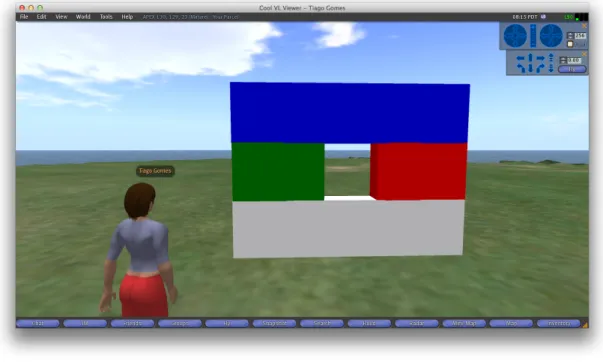
by accessing the edit option of the prim menu to set the corresponding value in a text box or to drag and drop the corresponding dimension arrow. Mapping a new texture to a prim is also achieved through the edit option, clicking the texture button and choosing a texture. The objects are very manageable through this creation process. However, to create a wall with a window, for example, it will not take less than 4 primitives for the most simplistic solution to be achieved (Figure 2.3). This makes the process very slow and inefficient when creating buildings.
Figure 2.3: Creating a wall with a window with 4 primitives
The most recent viewers already have support for uploading COLLADA mod-els. There are also 3D libraries on-line with several models (e.g. google 3D ware-house2). This enables the reuse of previously built models. Nevertheless, the
building process, and in particular, the building of structures that can be popu-lated with other objects, can be improved and benefit from the advantages of new modelling techniques and modern languages.
2.3.3
Conclusions
In this chapter the APEX framework and its virtual environment component, the OpenSimulator 3D application server were described. The OpenSimulator appli-cation server has an API that can be used to interact with the virtual environment programatically. This API can be used to develop solutions for the virtual envi-ronment generation problem since it provides methods to create objects in the virtual world.
Although APEX is a valuable framework for prototyping ubiquitous environ-ments, the support for developing virtual environments is a feature of the frame-work that can be further improved, due to the issues related to the tool that is currently used to describe the environments, and to the fact that this tool is not tuned for the APEX needs. The most limited process is the development of the building’s structure. The insertion of isolated objects can be satisfactorily achieved using models from on-line libraries. Relevant topics for virtual environment’s de-velopment are described in the next chapter.
Chapter 3
Developing Virtual Environments
3.1
Introduction
In the previous chapter, the APEX framework and its components were described. The framework uses OpenSimulator to manage the virtual environments. It was said that the current tool for the virtual environment generation process does not satisfy the APEX framework needs. In this chapter some possible approaches to solve this problem are addressed.
3.2
OpenSimulator Archives (OARs)
OpenSimulator archives were created to ease the transport of whole regions from one server instance to another. The information in the OAR is not only about the shapes in the region, but also about the textures that cover them, the items contained in them, like sounds, and also about terrain (see [Jus09] for more details). All that information must be present in a single file because a whole region can be stored inside the OAR.
The .oar extension is used to identify the OARs, however these files are actually no more than common zipped tar archives (.tar.gz). By unpacking one of these files, one can see its internal structure. The folders and files contained in its root path are shown in Figure 3.1.
Figure 3.1: OpenSim Archives internal format files and directories:
• The ”archive.xml” is known as the archive control file. This file contains in-formation about version compatibility, a boolean value that specifies whether the OAR contains assets or not (see below), and a manifest of the regions included. It is written in eXtensible Markup Language (XML) format. • The ”assets” directory contains all the assets in the archive. In the OpenSim
context, assets are media files (e.g. textures, sounds, video and text) that are formatted and ready to be used in the virtual environment. There is no need to split them into regions because assets can be shared. Each asset name consists on an ”uuid”, which is used to identify the asset, and consequently must be unique, followed by the ”asset type”, which is used to identify the asset type, and finished with the asset extension which allows the asset to
be associated with specific editors.
• The ”landdata” directory contains all the parcels in the region. A parcel is an user created subdivision of a region. Information for each parcel is stored in separate XML files. The file name consists on as ”uuid” that unambiguously identifies the parcel.
• Each file in the ”objects” directory represents an object in the region. The file format used is OpenSim’s XML2. Each file name is by default composed of an object name, followed by its position in 3D cartesian coordinates, and ending in its unique identification (uuid). Although, unlike asset file names, any component of its name can be changed without affecting the object itself. So these files can have any name because the information about the object is only taken from the XML.
• The ”settings” directory contains the settings information for the region in the XML format. These are the settings that can be accessed on the ”region settings” menu of any OpenSimulator viewer. For example, the ability to fly is a setting that can be found in these files. The file name will be the same as the region name.
• Finally the ”terrain” directory contains the terrain file for the region, stored in raw format. Its extension must be ”.r32” and the file name is also the same as the region name.
The OARs format was designed in order to overcome three main problems [Jus08]. First, to make it easy for people to read and write different OpenSim files within an archive. Since OARs are common compressed files, anyone can open them and manage their content. Moreover, the files within the archive are laid out to make it easy to perceive the different types of data. Second, to make it easy to compose two region archives into a single region archive. This means that the contents in one region can merge into another one just by copying the respective files from a directory to the other. Note however, that files in the terrain directory are an exception because one terrain relief would override the other. Hence this feature is more useful for archives that are collections of objects rather than whole
regions. Finally, to make it possible to compose archives from scratch. There is no obligation to create an OAR by saving the contents of an existing region. The user can create his own files outside of the system and compose the archive.
OAR archives are the most suitable solution to share virtual objects within OpenSimulator since they were created for it and are completely adapted to it. They store every single detail of a whole region so that no information is lost when sharing amongst different application server instances. However these files can be a problem in the context of the APEX environment generation due to the fact that every time they are loaded, the previous environment is overwritten, causing some information in other APEX components to be erased or unlinked. This issue would require the recreation of these information for the framework to work properly. Thus, consuming more time in the redesign process. One of the objectives of the APEX framework is to streamline the prototyping of ubiquitous environments.
Despite being possible to manually create OAR files, they are a technical file format and not the simplest way to build virtual environments.
3.3
Virtual environment modelling languages
An alternative to the archives discussed above (OAR) is the creation of virtual models from 3D modelling languages. Using modelling languages to create 3D models can provide a high level of customisation and accuracy. Although, the compatibility is imposed by the OpenSimulator ability to import the generated models, which currently is limited to COLLADA files. This problem can be solved by converting an input language format into the COLLADA format. Actually there are several tools that are able to make this conversion (e.g. Blender, MeshLab). Another advantage of the modelling languages is that the models can be simply added to the virtual environment without affecting any existent objects and there is no need to overwrite the whole region.
3.3.1
Scene graphs based languages
Scene graphs are a well known structure that is very useful when arranging the logical and spatial representation of a graphical scene. They can be used to repre-sent 3D virtual worlds in computer graphics applications. A general definition of a scene graph is that it is a collection of nodes linked by edges and organised in a tree structure, so each node can have several children nodes but only one parent node. This is a hierarchical structure, which means that any operation applied to a parent is also applied to its children. This property is called state inheritance. The nodes in the scene graph store the information to manage the scene, while the edges link them in a way related to the spatial and semantic arrangement of the objects. A common feature of scene graphs is to group related objects into a compound object which can then be transformed as a single object.
Figure 3.2: Scene graph example of a house There are three different types of nodes in a scene graph:
• The root node is the first and it is the only one that does not have a parent node. All the other nodes are connected either directly or indirectly to the root node. This means that every leaf applies its operations, since they all derive from it.
• The internal or group nodes are the nodes that stand between the root and the leaf nodes. They are commonly used to preform a group of 3D operations like translations, rotations, scaling or shearing. Internal nodes describe the virtual world’s state (position, orientation and size).
• The leaf nodes have no children nodes, so they cannot be parent nodes. They contain geometric data with the succession of operations of their ancestors (in a direct line from the root node) applied to them.
An example of a scene graph is shown in Figure 3.2. In this example the entire house is rotated in the root node, then every room is placed in their respective position by a translation operation and finally chairs and beds are rendered in each of the rooms.
Scene graphs are high level graphics languages that avoid procedural aspects of low-level ones like OpenGL [Woo03]. Scene graphs use a low-level graphics tool to render the scene, however they are completely independent from each other. The scene graph describes and updates the scene and indicates the content to be rendered by the underlying API.
Some languages that implement scene graph structures are described below.
Virtual Reality Modelling Language (VRML)
The Virtual Reality Modelling Language (VRML) is a standard for representing 3D models. It was created by the Web3D Consortium1 to represent 3D interactive
vector graphics on the World Wide Web (WWW). Despite using the scene graph’s structure, it does not have a reference to a root node in its syntax. The root node is ambiguous and can be any of the other nodes.
VRML has default support for simple graphics primitives like cubes or spheres.
X3D
X3D is an XML based standard that is used for representing 3D computer graphics. It is the successor of VRML and features some extensions to its predecessor like the access to programming languages. It was also created by the Web3D Consortium. Due to the fact that it is based on XML, it benefits from some advantages like the freedom to define your own syntax. This feature makes the language very versatile and allows it to be easily adapted to any situation.
COLLADA
The COLLADA schema development was initiated by Sony Computer Entertain-ment2 and the project’s objective was to create a Digital asset exchange (DAE)
format [AB06]. Nowadays many other Digital content creation (DCC) [EV01] tool companies are working together joining their expertise to improve the format. It was built using other open standards (e.g. XML, UTF8, XPath etc.) and it is also an open standard.
COLLADA defines an XML database what enables anyone to freely exchange COLLADA models without loosing any information. Its schema can be easily extended by end users for their own purposes. It was not designed to fit some specific needs but to be a media content holder for any target platform. It also supports all the basic features that a 3D interactive application needs, including shader effects and physics simulation.
The COLLADA format has a relevant advantage from the formats described before. It is the only format supported by OpenSimulator for now. So no conver-sions are needed in order to upload COLLADA files into OpenSimulator.
3.3.2
Procedural modelling
The generation of large 3D environments is a very time consuming task when developing virtual environment applications. In a large scene, there are sometimes very similar constitutes that have very similar building processes too. Usually, however, there are small changes between such constitutes. Consider for example
the development of a virtual environment representing a care home. There would be a great number of rooms in it, and every room would be slightly different from the other, but with same kind of objects and the same kind of sizes. An approach where every object is developed individually would be unfeasible, given the effort and time it would implicate, when we just want very similar rooms with some small differences. A possible approach for this problem is to provide a set of parameters to a function or algorithm that can generate those slight differences. This process is called Procedural modelling.
Figure 3.3: Procedural building phases
Using procedural methods for generating 3D environments has proven to be a good solution for problems like the one described before. Procedural modelling techniques require reduced human effort, by automatically generating 3D models [SC11]. However, the process needs guidelines (parameters) from the users to transform the objects as desired. The process is usually characterised by having a set of generation rules that transform groups of the most simple objects into most complex ones adding small changes to them, step by step. However, the results produced may have low graphical details quality which means that additional tuning might be required.
Fractals [Pen84], Lindenmayer Systems (L-Systems) [Tal96] or Generative mod-elling are some examples where procedural modmod-elling techniques are used. For example, L-Systems are usually used in virtual reality applications for modelling plant ecosystems. Geospatial L-systems [CBSF07] are an extension to the stan-dard L-Systems that incorporates geospatial awareness so they can be used in a geographic context like the development of virtual urban environments. An appli-cation that perceives the spacial relations between objects in an urban environment
can determine for example that a building wall cannot have windows because there is another wall too close.
3.4 3D modelling tools
3D modelling languages are the basis for the creation of virtual environments, although it is unthinkable describing a whole building by manually writing a 3D model using these languages. Nowadays, there are several tools for developing virtual environments which are based on these languages, however they do not im-ply writing the models manually, or even to have knowledge about the underlying language. Instead, they provide Graphical User Interfaces (GUIs) that receive the user operations and translate them into the underlying language.
3D modelling tools help people develop virtual models of 3D scenarios and support their edition and manipulation. A 3D model is composed by a polygon mesh or a set of points that give it its physical aspect. A user can add new points to the mesh, delete or position the existing ones, giving the model the desired shape. Additionally, textures can be mapped to the mesh points so that the model changes its appearance. 3D modelling tools usually have a list of features that support these operations and many other useful ones. Generated 3D models can be exported into files. There are several alternatives to express these models, as discussed in the previous section. Modelling tools may support some of these formats, either by importing or exporting, giving models compatibility with other 3D applications such as OpenSimulator.
There is a wide diversity of 3D modelling tools in the market. We can find both professional or more simple solutions for home use. Also, some are licensed under commercial licenses and others under open source licenses.
Here we aim to find a solution, composed by one or more tools, that can be integrated with the APEX framework in order to ease Virtual Environment (VE) creation. This solution should be a robust, scalable and easy to use tool for the development of buildings for prototyping ubiquitous environments. Thus, some criteria are going to be taken into consideration in order to serve the project needs. So, the solution must:
• be an agile tool for buildings development. The use of the APEX framework is based on the development of virtual buildings to test ubiquitous systems; • have an intuitive and efficient interface granting ease of use. The use of the APEX framework shows that the current tool (OpenSimulator compatible viewer) is not the ideal solution in the buildings context. An easy to use tool will grant quicker results;
• be accurate enough to create scenarios with acceptable detail. The accuracy of the scenario is also a very important aspect in the APEX framework. Scenarios with low accuracy may lead the user to not recognising the place; • support interoperability with OpenSimulator. This is a mandatory aspect, since OpenSimulator is the tool used to manage the virtual environment in the APEX framework;
• be composed by open source software so that we can easily get its source code and develop an integration layer with APEX framework.
This research is strongly based in these criteria. So, many other features of 3D modelling software, that are important in a wide range of cases, will not have a big emphasis in this analysis because they are not crucial for the project development and performance, and consequently we are not as concerned about them.
Some chosen tools are going to be described and analysed below, taking into acount the criteria cited above.
3.4.1
Blender
Blender3 is an open source 3D computer graphics software project. It is licensed
under the GNU General Public License (GNU GPL) so the public is free to use its source code. Blender is a multiple platform tool, it is available for download on its website for Windows, Mac OSX and Linux amongst other versions. Its initial stable release was made in 1995 and currently it is on its 2.68 stable version.
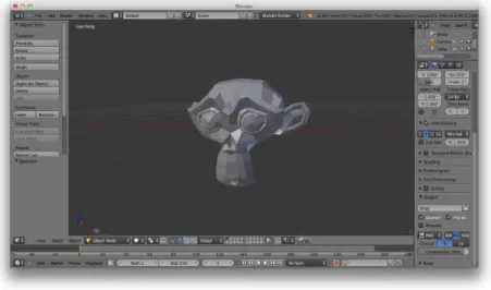
Blender is a powerful tool that has many useful features for video games, visual effects and many other 3D interactive applications creation. Here we are partic-ularly interested in 3D model creation and its strong compatibility with different 3D object file formats. It is fully compatible with the COLLADA format among several others. Some of the most relevant features for this project are:
• Texture management; • Mesh manipulation;
• Support for importing and exporting several formats like COLLADA, Wavefront OBJ (OBJ), eXtensible 3D Graphics (X3D) or VRML amongst many others.
Figure 3.4: Manipulating 3D meshes with Blender
Blender has a large community of users and is widely accepted worldwide. Since Blender is an open source project we can easily improve it or create a plugin in order to integrate with the APEX framework, if needed.
3.4.2
MeshLab
MeshLab4 is a system developed for graphical mesh processing. As with Blender,
it is an open source project licensed under GNU GPL. It is easy to get its source
code and develop a plugin to enhance MeshLab’s list of features. MeshLab is highly based on the VCG Library5 for all the core tasks on mesh processing. MeshLab is
a cross platform product, it is even available for mobile platforms and is currently on its 1.3.2 version.
Figure 3.5: MeshLab in action [CCR08]
Amongst other important aspects, MeshLab was developed with three main objectives [CCR08] in mind:
• Ease of use - This means that no advanced 3D manipulation skills are needed to use MeshLab;
• 3D scanning oriented - Since there are already several strong players on mesh edition, MeshLab is particularly concerned about mesh processing tasks like cleaning, inspecting or converting meshes;
• Efficiency - MeshLab is a very efficient tool that can process large amounts of primitives on 3D scanning meshes.
MeshLab provides an extensive list of useful features on mesh processing [CCC+08].
Some of the most relevant characteristics of this project are listed below:
• Interactive selection and deletion features can be used to prune an imported mesh and adjust it to contain only what the user needs;
• The import and export features support many of the most used 3D file formats including COLLADA. Thus, any created or managed meshes can be transformed so that OpenSimulator can recognise them;
• Mesh clearing and remeshing filters can be used to remove the noise and redundancy in a model or to fill mesh holes in order to make it less complex and more lightweight;
• The measuring tool can be used to scale the imported mesh to the desired size by defining linear measures between pairs of points in the mesh.
This software is an efficient and useful tool for the mesh development. It can be used in the project to increase the objects’ efficiency (remove redundant information) and also to give them compatibility with OpenSimulator since it supports a wide list of 3D object file formats.
3.4.3
Sweet Home 3D
Sweet Home 3D (SH3D)6 was created for fast interior design. It is a fully tuned
tool for building development. The program is aimed at people who want to quickly design their home’s interior. Nevertheless, it can be used in numerous other contexts, due to its potential and ease of use.
Sweet Home 3D (SH3D) is also an open source project licensed under GNU GPL. Its source code can be easily downloaded at the website. The tool is very well sup-ported and there are also some guides on how to develop plugins for SH3D. It is based on JAVA7 and is a cross platform tool, it can be even used online on its
website with no limitations. Currently the software is on its 4.1 version.
6http://www.sweethome3d.com (August, 2013) 7http://www.java.com (August, 2013)
Noteworthy is its ease of use with a low learning curve due to its approach for developing virtual scenes. The SH3D user interface is not a common 3D de-velopment tool interface, it is adapted to building dede-velopment and this was an interesting aspect about this software. It is essentially based on drag and drop gestures and the most important is that a 3D scene is transformed in a two-dimensional (2D) plan where you can develop your building, thus dramatically reducing the complexity of the development task. Its interface is composed by four panels (see Figure 3.6):
Figure 3.6: Sweet Home 3D interface
• Panel 1 is the furniture catalog. There, it is possible to find objects to add to the scene. A new object can be added to the scene by dragging it from this panel and dropping it on the home plan panel explained below. Moreover, it
is possible to add new objects to the furniture catalog simply by importing them.
• Panel 2 is the home furniture list. This list contains all the objects that were already added to scene. The objects can be selected and their characteristics edited.
• Panel 3 is the home plan. It is a 2D plan where the scene can be created. This is the main pane, every object on the scene must be added to it, either by dropping or creating it. It displays the building under construction as seen from the top.
• Finally, panel 4 is the home 3D view. This is the render pane, where the resulting 3D scene can be seen. It is updated in real time and the scene can be seen either from the top or from a virtual visitor’s view at any chosen point.
Another nice feature of SH3D is that it can set a house blueprint as the home plan background. After setting the correct dimensions for the blueprint it is easy to pounce the walls, doors, windows or any kind of components in a building. This software is a mature player in the building development context, and so, it has a strong potential for the APEX virtual environment generation problem.
Despite having these useful features for virtual buildings development, Sweet Home 3D (SH3D) is not able to export generated models into COLLADA files. The 3D file format generated by SH3D is Wavefront OBJ (OBJ). So, an auxiliary software is needed in order to convert the output file from SH3D to an OpenSim-ulator readable format.
3.5
Discussion
Some possible approaches for the APEX framework environment generation were briefly studied and its main technical features were presented. Three main ap-proaches were analysed:
• Use the application server API to build the necessary objects in the virtual environment;
• Use a modelling language to describe the virtual objects and generate an OAR archive to load them to the virtual environment;
• Use a modelling language to describe the virtual objects and convert them into a COLLADA file that is legible by the application server.
The use of OARs is going to be discarded. Despite the fact that it could be a very powerful solution and probably the most suitable for the 3D application server, OARs cannot be used to add objects to an existing region because the whole region is replaced when they are loaded. APEX users need to build the environment incrementally, which means that objects can be added, removed or changed in the virtual environment during its development. This would not be a problem if the environment component was the only one in APEX framework architecture, however it has also other components like the behaviour one that would loose information about all the current objects and would suffer from malfunction every time that a region was reloaded.
Still on the possible approaches, a consideration about the second one is that only scene graph based modelling languages will be taken into account from here on. This is because the procedural modelling approaches do not meet the needs of a standard user of the APEX framework. They were developed for large scenarios with low detailed objects, but when prototyping ubiquitous systems we need to provide very detailed scenarios to the end users in order to ease their immersion in the virtual world.
Thus, only two approaches are possible now, using 3D modelling tools or using the OpenSimulator API. Both of them are going to be properly analysed below.
Some 3D modelling tools have really interesting features for this project, how-ever some other features in these softwares do not fit with APEX framework needs. For example, MeshLab has some nice tools for mesh optimisation, although it is unfeasible creating a whole 3D building using its user interface, moreover it would not add value over the current solution (an OpenSimulator compatible Viewer). Another example is that Sweet Home 3D has a very helpful interface and a well adapted approach for building creation, however it is not able to export generated 3D models into an OpenSimulator readable format. Blender provides an easy way to change the textures and do other manipulation tasks in a mesh and is able to
convert almost any 3D file format into another one, nevertheless its interface, as well as it happens in MeshLab case, leaves much to be desired in terms of buildings development.
The other alternative for solving the research problem is to use the Open-Simulator API. The OpenOpen-Simulator API provides methods to interact with the virtual environment. It is possible to make almost any operation that could be made through a server window or a compatible viewer. Adding a GUI to a region module developed using the API, can ease the use of the operations implemented inside this module.
3.6
Conclusions
Some powerful alternatives of 3D development applications were presented in this chapter, as well as the format of the OpenSimulator region ARchives (OARs), the standard files for storing and sharing whole OpenSimulator virtual regions. Moreover, a brief analysis of some virtual environment modelling languages that can be useful later in this project was made.
The 3D modelling tools described in this chapter have some limitations regard-ing the APEX framework virtual environment generation requirements. Despite having those limitations when they are applied in a standalone way, they can constitute some good solutions for the project’s problem when applied together, joining their useful features. Filling the gaps of each other they can become a both efficient and well adapted tool which fills APEX framework needs, thus getting the best of both worlds. There are several more tools that can be used to develop vir-tual environments (e.g. Google SketchUp8, Maya9), however some of them are not
open source, or do not have support COLLADA files, or even do not add value to the tools described. The following table shows an evaluation of the tools described before taking into account the relevant features for this project. This evaluation was made considering the projects context and not a context of standard use of 3D modelling.
Looking at the Table 3.1 we can conclude that we need to join more than
8http://www.sketchup.com/ (October 2013) 9http://www.autodesk.com/maya (October 2013)
Features Environment Dev. Ease of use Accuracy Collada support Open Source
Blender X X X
MeshLab X X X X
Sweet Home 3D X X X
Table 3.1: 3D tools relevant features
one tool to get a complete solution that serves the project’s needs. Thus, three hypothesis were considered:
• Joining Sweet Home 3D (SH3D) with MeshLab; • Joining Sweet Home 3D (SH3D) with Blender; • Joining the three tools.
Since all of the tools are open source softwares, we are able to get their source code and integrate with each other. These three potential solutions are going to be analysed in the next chapter. Moreover, the approach that uses the OpenSimulator API is also analysed.
Chapter 4
Virtual environment development
tool
4.1
Introduction
In the end of the previous chapter it was concluded that there are two main possible approaches for the solution of the virtual environment generation problem in the APEX framework. One of the possible solutions is to use a group of 3D modelling tools that serve a set of requirements imposed by the APEX framework needs in order to make a joint coherent solution. An analysis of the relevant features of the modelling tools was made, and it was concluded that these tools could not be applied in a standalone way. Instead, they should be applied together in order to meet all the requirements.
The other approach is to use the OpenSimulator API. This approach assumes the creation of an OpenSimulator region module to interact with the virtual envi-ronment, and a user interface to call the respective methods on the region module. The user interface must be adapted to building creation so that it can streamline the virtual environment generation of a standard APEX framework project.
In this chapter, both of the approaches are going to be fully described and analysed. More than one solution may be presented for each approach. For analysis purposes, the model of a building will be used, so that the final product can reflect advantages and disadvantages for each solution. Moreover the time spent to build
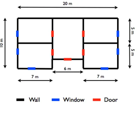
the model for each solution is one of the most important aspects to the project, since the main objective is to streamline the virtual environment generation. The blueprint of the building can be seen in Figure 4.1.
Figure 4.1: Building model blueprint
This is a simple medium scale building, with four rooms and a central hall. It has two windows in each of the front rooms and one window in each of the back rooms. Each room has an internal door that gives access from the central hall to the respective room. Moreover there is an entrance door that gives access to the building. The model of the building must be created using each solution so that results can be analysed and compared. At the end of the chapter, a comparison between the solutions will be made and the one that best fits the requirements will
be chosen.
4.2 Using 3D Modelling tools
The first approach that is going to be described is the use of the 3D modelling softwares to form a complete tool that meets the project requirements and can be adapted to the APEX framework. For this approach, three different solutions were found, although only two are going to be taken into account (see Figure 4.2). The one that joins the three tools was discarded because MeshLab and Blender play very similar roles in this task, thus using both in the same solution would introduce some unnecessary redundancy.
Figure 4.2: Using 3D modelling tools approach
All the solutions found have to include SH3D because this is the only tool that has a satisfactory approach to the development of buildings:
• Solution 1 - SH3D and Blender • Solution 2 - SH3D and MeshLab
Figure 4.3: SH3D Building development
Each of these solutions is presented in the next sections. Both of them, however, start with a common task that is the definition of the building in SH3D.
4.2.1
Modelling the Building in SH3D
After launching the tool, the external walls started to be designed in the home plan taking the blueprint (Figure 4.1) measures into account. After that, the internal walls were designed and, to finish the building structure, all the windows and doors were added in the respective places. This was done by dragging and dropping them from the furniture catalog to the home plan panel. When the structure was complete, some textures were attached to the walls in order to give them a more realistic appearance. For this, each wall was selected in the home plan panel and its texture was edited by selecting the option ”change walls”. During this process it was possible to see the building evolution in the home 3D view panel in real time. This is a really useful feature since we can foresee the final aspect of the 3D model while we are designing the building. This enables us to quickly correct some imperfections that show up while the development is being made. The final aspect of SH3D when the building development was finished can
be seen in Figure 4.3.
In the end of the development process the 3D model was exported into the Wavefront OBJ (OBJ) format so that it could be used in the next by the 3D modelling software.
The process of developing and exporting the whole building model took about 7 minutes. This is going to be used as the base time for the solutions that are going to be described below using Sweet Home 3D (SH3D).
Figure 4.4: Using Blender to transform the building model
4.2.2
SH3D and Blender
The result of developing the building model in SH3D was a 3D model in the OBJ file format as it was said before. Some more files, such as texture images, were attached to the OBJ file. The next step in this process was to open the Blender application and import the resulting files into its environment. Here Blender plays basically a conversion role for the previously generated building model. After im-porting the 3D model, the building was rendered in the application main panel. By
selecting the export into COLLADA option, Blender created an output file con-taining the model of the building in the respective format. This task is illustrated in Figure 4.4.
With this step we obtained an OpenSimulator readable 3D model. So after that we just uploaded the resulting model to a local server instance using a compatible viewer. This process took about 6 minutes to complete, so the final time for this solution was about 13 minutes. Notice however that, if this solution is chosen, this time can be improved by automating the conversion process.
Figure 4.5: Result for the solution SH3D+Blender
Despite being an easy to implement solution, it revealed some problems in terms of compatibility of 3D file formats between Blender and OpenSimulator. The generated COLLADA model had a texture attached to the walls although it was not visible when uploaded to the OpenSimulator server. The resulting model had a homogeneous aspect and walls were hardly distinguished. Figure 4.5 shows the resulting model for this solution.
4.2.3
SH3D and MeshLab
This solution is slightly different from the one described before. The output (OBJ) 3D model from SH3D is also used as an initial model, although this time MeshLab is used instead of Blender for the conversion task.
Figure 4.6: Using MeshLab to transform the building model
The process started opening MeshLab and importing the resulting mesh from the model of the building development in SH3D. As MeshLab also had support for OBJ file format meshes, the same file used in the previous solution was used here. After importing the model it was possible to see it in the MeshLab render panel (see Figure 4.6). After that, there were several mesh optimisation options available, but for the purpose we were just concerned about OpenSimulator compatibility. So the mesh was exported into a COLLADA file by choosing the option ”Export Mesh as” and selecting the DAE extension. This process resulted in a COLLADA 3D model of the building that could be easily uploaded to an OpenSimulator server instance as it was made in the previous solution. Thus, after launching a local server instance the model was uploaded to it using a compatible viewer and it was possible to see the final result for this solution in action (see Figure 4.7).
Figure 4.7: Result for the solution SH3D+MeshLab
The time elapsed since MeshLab was open until the result could be seen on OpenSimulator took about 5 minutes too, so the final time is very similar to the previous solution. Also, this time can be improved if this solution is chosen by doing the conversion task programatically.
This solution was also an easy to implement one. Although, the final result showed up some evident differences when compared to the previous one. Here the resulting COLLADA model seem to be fully compatible with OpenSimulator. The textures were uploaded correctly and the building had the same aspect as it was in SH3D. The result of this solution can be seen in Figure 4.7.
4.3
Using OpenSim API
The second approach described for solving the APEX framework environment generation problem is the use of the OpenSim Application Programming Interface (API). This approach can generate more customised solutions since it assumes the development of an OpenSimulator region module that interacts directly with
![Figure 2.1: Logical architecture of the execution environments in APEX frame- frame-work (from [Sil12])](https://thumb-eu.123doks.com/thumbv2/123dok_br/17763486.835965/29.892.187.697.178.484/figure-logical-architecture-execution-environments-apex-frame-frame.webp)


![Figure 3.5: MeshLab in action [CCR08]](https://thumb-eu.123doks.com/thumbv2/123dok_br/17763486.835965/47.892.258.635.318.619/figure-meshlab-in-action-ccr.webp)