BJRS
03-1A (2015) 01-12Monte Carlo
modeling of multileaf collimators using the
code Geant4
A. C. H. Oliveira
a,c; J. W. Vieira
b; F. R. A. Lima
a,ca
Departamento de Energia Nuclear (DEN), UFPE, 50670-901, Recife-PE, Brasil. [email protected]
bLaboratório de Dosimetria Numérica (LDN), IFPE, 50740-540, Recife-PE, Brasil.
cCentro Regional de Ciências Nucleares do Nordeste (CRCN-NE), CNEN, 50740-540, Recife-PE, Brasil.
ABSTRACT
Radiotherapy uses various techniques and equipment for local treatment of cancer. The equip-ment most often used in radiotherapy to the patient irradiation is linear accelerator (Linac). Among the many algorithms developed for evaluation of dose distributions in radiotherapy plan-ning, the algorithms based on Monte Carlo (MC) methods have proven to be very promising in terms of accuracy by providing more realistic results. The MC simulations for applications in radiotherapy are divided into two parts. In the first, the simulation of the production of the radia-tion beam by the Linac is performed and then the phase-space is generated. In the second part the simulation of the transport of particles (sampled phase-space) in certain configurations of irradia-tion field is performed to assess the dose distribuirradia-tion. Accurate modeling of the Linac head is of particular interest in the calculation of dose distributions for intensity modulated radiation thera-py (IMRT), where complex intensity distributions are delivered using a multileaf collimator (MLC). The objective of this work is to describe a methodology for modeling MC of MLCs us-ing code Geant4. To exemplify this methodology, the Varian Millennium 120-leaf MLC was modeled. The dosimetric characteristics (i.e., penumbra, leakage, and tongue-and-groove effect) of this MLC were evaluated. The results agreed with data published in the literature concerning the same MLC.
1. INTRODUCTION
Radiotherapy uses various techniques and equipment for local treatment of cancer. The equip-ment most often used in radiotherapy to the patient irradiation is linear accelerator (Linac). Among the many algorithms developed for evaluation of dose distributions in radiotherapy plan-ning, the algorithms based on Monte Carlo (MC) methods have proven to be very promising in terms of accuracy by providing more realistic results.
The MC simulations for applications in radiotherapy are divided into two parts. In the first, the simulation of the production of the radiation beam by the Linac is performed and then the phase space is generated. The phase space contains information such as energy, position, direction, etc. of millions of particles (photons, electrons, positrons). In the second part the simulation of the transport of particles (sampled phase space) in certain configurations of irradiation field is per-formed to assess the dose distribution in the patient (or phantom).
Accurate modeling of the accelerator head is of particular interest in the calculation of dose dis-tributions for intensity modulated radiation therapy (IMRT), where complex intensity distribu-tions are delivered using a multileaf collimator (MLC). Using the latter device, multiple static segments can be superimposed for delivering IMRT with the ‘step and shoot’ technique or fields can be composed dynamically, by sweeping the leaves across the treatment field during radiation delivery (‘sliding window’ or ‘dynamic’ technique) (HEATH; SEUNTJENS, 2003).
The MLC is composed of two banks of metal leaves that move perpendicularly to the radiation beam. The sides of the leaves are designed to have a kind of fit between them. This configuration is known as tongue-and-groove and has the objective to minimize the radiation transmitted be-tween adjacent leafs (LOVEROCK, 2007; VIEIRA, 2008; CASTRO et. Al., 2012).
The material of choice for leaf construction is tungsten alloy because it has one of the highest densities of any metal. Tungsten alloys are also hard, simple to fashion, reasonably inexpensive,
and have a low coefficient of thermal expansion (JERAJ; ROBAR, 2008). The mass density of the tungsten alloy used in the MLC leaves usually has to be ascertained for every Linac, due to variations in different Linacs (VERHAEGEN; SEUNTJENS, 2003).
The MLC is among the geometric structures of a Linac more difficult to model. The only way that the MLCs can be fully modeled is by MC methods, but this is a far from trivial task (VERHAEGEN; SEUNTJENS, 2003; JANG et. Al., 2006).
Significant differences in radiation spectrum in different sections of IMRT fields could have sig-nificant radiobiology effects (VERHAEGEN; SEUNTJENS, 2003). The dosimetric properties of the MLC depend very much on its technical design specifications and have to fulfill various in-ternational standards. The most important dosimetric parameters are the leakage and the lateral beam penumbra. The leakage refers to radiation that emerges through the air gaps between two leaves (interleaf) and refers to radiation not absorbed in the penetrated leaf material (intraleaf). The penumbra at a given depth is commonly defined as the distance between the 20% and 80% isodose lines of a 10×10 cm2 radiation field. Another investigated dosimetric characteristic is the tongue-and-groove effect which occurs if transversally neighboring fields are irradiated (TACKE et. Al., 2006).
Thus, it is important to model thoroughly the MLC for radiotherapy planning, for these dosimetric characteristics can significantly contribute to the absorbed dose in normal and sensi-tive organs (HEATH; SEUNTJENS, 2003).
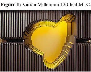
The objective of this work is to describe a methodology for modeling MC of MLCs using code Geant4. The Geant4 is one of the main MC codes used in medical physics, including innovative areas such as radiotherapy with heavy particles and image-guided radiation therapy. For exem-plify this methodology, the Varian Millennium 120-leaf MLC (Figure 1) was modeled, whose physical description is available in BEAMnrc Users Manual (ROGERS et. Al., 2011).
Figure 1: Varian Millenium 120-leaf MLC.
Source: Varian Medical Systems.
The Varian Millenium 120-leaf MLC consists of 80 inner leaves and 40 outer leaves (full leaf) whose width projects to 0.5 cm and 1.0 cm, respectively, at isocentre. A cross-sectional view of the inner and outer leaves is shown in Figure 2. The inner leaves are arranged in an alternating pattern of thick end towards the target (target leaf) and thick end towards isocentre (isocentre leaf). The leaf ends are rounded to maintain a fairly constant penumbra size as a function of the leaf position. The leaves are driven linearly in and out of the field by a motor driven lead screw which extends to within approximately 2 cm of the leaf end. A side view of a single leaf in Fig-ure 2 illustrates the driving screw hole which is a 3 mm slit in the leaf to allow travel of the lead screw. To minimize friction and allow the leaves to move freely, adjacent leaves are separated by a small air gap which is designated as the interleaf air gap. To avoid collisions between opposing leaves, a small air gap exists between a completely closed leaf pair. The combination of this abutting leaf gap and the rounded leaf ends also contributes to a significant leakage between each closed opposing leaf pair which is designated as the abutting leaf leakage.
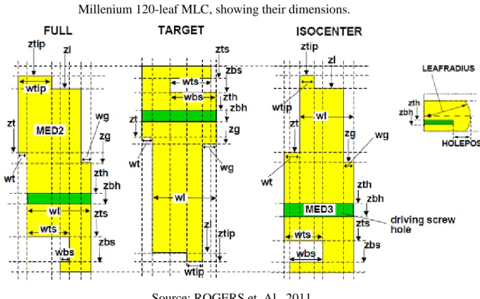
The Varian Millenium 120-leaf MLC was firstly modeled by Heath and Seuntjens (2003) by using code BEAMnrc. Posteriorly, there have been some modifications of inputs and some bugs were fixed by the developers of BEAMnrc and the model of the MLC was named DYNVMLC. The dimensions used to model the three types leaves are shown in Figure 2. The BEAMnrc is a computer code used to model any source of radiotherapy, in general Linacs (ROGERS et. Al., 2011).
Figure 2: Detailed cross-sections of the three leaf types (full, target and isocenter) of Varian
Millenium 120-leaf MLC, showing their dimensions.
Source: ROGERS et. Al., 2011.
Recently, Okamoto et. Al. (2014) modeled the Varian Millennium 120-leaf MLC (except the driving screw hole) using Geant4. For verifying the modeling, some tests were performed. For all tests, the calculations agreed with the measurements of an ionization chamber or radiographic film. However, it has not shown the methodology used for modeling of the MLC.
2. MATERIALS AND METHODS
The modeling MC of the MLC was performed from the physical description of Varian Millenni-um 120-leaf available in BEAMnrc Users Manual (ROGERS et. Al., 2011). But the values of the positions and dimensions of the leaves given as examples are not representative of a real Varian Millennium 120-leaf, just a template.
The collimator starts at Z = 482.5 mm (ZMinMLC) and has 60 leaves, 1-10 and 51-60 are FULL and 11-50 are TARGET/ISOCENTER pairs.
The 9.6.p02 version of Geant4 was used. The leaves of the MLC were built using two types of solid, G4Tubs and G4ExtrudeSolid, and the Boolean operation of subtraction (G4SubtractionSolid).
The solid G4ExtrudeSolid was used to build the cross-sections (CS) of leaves, by defining vertex positions relative to the center of the CS. It must be subtracted from the CS the driving screw holes (DSH) which can be built using solid G4ExtrudeSolid. The leaf ends were built subtracting from the CS a solid G4Tubs defined with the inner radius equal to 80 mm (LEAFRADIUS) and the height equal to LeafTh. LeafTh is the thickness of each type of leaf (wl+wt). Below are given the vertexes of the CS and of the DSH to three types of leaf, where HeightMLC is the height of leaves.
FULL (CS): {-0.5*LeafTh, 0.5*HeightMLC-(ztip-ZMinMLC)}, {-0.5*LeafTh+wtip, 0.5*HeightMLC-(ztip-ZMinMLC)}, {-0.5*LeafTh+wtip, 0.5*HeightMLC-(zl-ZMinMLC)}, {0.5*LeafTh-wg, 0.5*HeightMLC-(zl-ZMinMLC)}, {0.5*LeafTh-wg, 0.5*HeightMLC(zgZMinMLC)}, {0.5*LeafTh, 0.5*HeightMLC(zg0.5*HeightMLC(zgZMinMLC)}, {0.5*LeafTh, -0.5*HeightMLC)}, {0.5*LeafTh-wl+wts-wbs, --0.5*HeightMLC)}, {0.5*LeafTh-wl+wts-wbs, 0.5*HeightMLC-(zbs-ZMinMLC)}, {0.5*LeafTh-wl+wts, 0.5*HeightMLC-(zbs-ZMinMLC)}, {0.5*LeafTh-wl+wts, (zts-ZMinMLC)}, {0.5*LeafTh-wl, 0.5*HeightMLC-(zts-ZMinMLC)}, {0.5*LeafTh-wl, 0.5*HeightMLC-(zt-ZMinMLC)}, {-0.5*LeafTh, 0.5*HeightMLC-(zt-ZMinMLC)}.
FULL (DSH): {0.5*LeafTh-wl-1.*mm, 0.5*HeightMLC-(zth-ZMinMLC)}, {0.5*LeafTh
+1.*mm, 0.5*HeightMLC-(zth-ZMinMLC)}, {0.5*LeafTh+1.*mm, 0.5*HeightMLC-(zbh-ZMinMLC)}, {0.5*LeafTh-wl-1.*mm, 0.5*HeightMLC-(zbh-ZMinMLC)}.
TARGET (CS): {-0.5*LeafTh, 0.5*HeightMLC)}, {0.5*LeafTh-wbs+wts, 0.5*HeightMLC},
{0.5*LeafTh-wbs+wts, (zts-ZMinMLC)}, (0.5*LeafTh-wbs, 0.5*HeightMLC-(zts-ZMinMLC)}, {0.5*LeafTh-wbs, 0.5*HeightMLC-(zbs-ZMinMLC)}, {0.5*LeafTh,
0.5*HeightMLC-(zbs-ZMinMLC)}, {0.5*LeafTh, 0.5*HeightMLC-(zg-ZMinMLC)}, {0.5*LeafTh-wg, 0.5*HeightMLC-(zg-ZMinMLC)}, {0.5*LeafTh-wg, 0.5*HeightMLC-(ztip-ZMinMLC)}, wg, 0.5*HeightMLC-(ztip-0.5*HeightMLC-(ztip-ZMinMLC)}, {0.5*LeafTh-wtip-wg, 0.5*HeightMLC-(zl-ZMinMLC)}, {0.5*LeafTh-wl, 0.5*HeightMLC-(zl-ZMinMLC)}, {0.5*LeafTh-wl, 0.5*HeightMLC-(zt-ZMinMLC)}, {-0.5*LeafTh, 0.5*HeightMLC-(zt-ZMinMLC)}.
TARGET (DSH): {-0.5*LeafTh-1.*mm, 0.5*HeightMLC-(zth-ZMinMLC)}, {0.5*LeafTh+
1.*mm, 0.5*HeightMLC-(zth-ZMinMLC)}, {0.5*LeafTh+1.*mm, 0.5*HeightMLC-(zbh-ZMinMLC)}, {-0.5*LeafTh-1.*mm, 0.5*HeightMLC-(zbh-ZMinMLC)}.
ISOCENTER (CS): {0.5*LeafTh-wl, 0.5*HeightMLC-(ztip-ZMinMLC)}, {-0.5*LeafTh+wtip+wt, 0.5*HeightMLC-(ztip-ZMinMLC)}, {-0.5*LeafTh+wtip+wt, 0.5*HeightMLC-(zl-ZMinMLC)}, {0.5*LeafTh-wg, 0.5*HeightMLC-(zl-ZMinMLC)}, {0.5*LeafTh-wg, 0.5*HeightMLC-(zg-ZMinMLC)}, {0.5*LeafTh,
0.5*HeightMLC-(zg-ZMinMLC)}, {0.5*LeafTh, -0.5*HeightMLC)}, {-0.5*LeafTh+wts-wbs,
-0.5*HeightMLC)}, {-0.5*LeafTh+wts-wbs, 0.5*HeightMLC-(zbs-ZMinMLC)}, {-0.5*LeafTh+wts, 0.5*HeightMLC-(zbs-ZMinMLC)}, {-{-0.5*LeafTh+wts, 0.5*HeightMLC-(zts-ZMinMLC)}, {-0.5*LeafTh, 0.5*HeightMLC-(zts-0.5*HeightMLC-(zts-ZMinMLC)}, {-0.5*LeafTh, 0.5*HeightMLC-(zt-ZMinMLC)}, {-0.5*LeafTh+wt, 0.5*HeightMLC-(zt-ZMinMLC)}.
ISOCENTER (DSH): {-0.5*LeafTh-1.*mm, 0.5*HeightMLC-(zth-ZMinMLC)},
{0.5*LeafTh+1.*mm, 0.5*HeightMLC-(zth-ZMinMLC)}, {0.5*LeafTh+1.*mm,
0.5*HeightMLC-(zbh-ZMinMLC)}, {-0.5*LeafTh-1.*mm, 0.5*HeightMLC-(zbh-ZMinMLC)}.
A tungsten alloy with a composition of 90% tungsten, 6% nickel, 2.5% copper and 1.5% iron and density of 17.7 g/cm3 were used for the leaf material (HEATH; SEUNTJENS, 2003; TYAGI et. Al., 2007). The interleaf air gap of 0.06 mm was used (HEATH; SEUNTJENS, 2003; ROG-ERS et. Al., 2011).
To validate the modeling of the MLC, dosimetric characteristics (i.e., penumbra, leakage, and tongue-and-groove effect) were evaluated based on the methodology presented by Heath and Seuntjens (2003).
The MLC model was added to the application SSLinacs (Simulation System of Linacs) (OLIVEIRA et. Al., 2013). This application contains a 6 MV Linac model. The cutoff range for the production of secondary particles in the MLC was set to 0.01 mm. The volume of detection for obtaining the phase space was modeled as a solid G4Box with sides adjusted to the opening of the beam and was positioned just below the MLC (600 mm from the electron target). From this phase space, dose distributions were obtained in a water phantom. The dose percentages were normalized relative to the maximum dose.
To measure the leakage, the MLC (defining a field of 0 × 0 cm2) was irradiated with a field of 10 × 10 cm2 and the water phantom with a voxel size of 10 × 1 × 5 mm3. To evaluate the penumbra, the MLC (defining a field of 10 × 10 cm2) was irradiated with a field of 15 × 15 cm2 and the wa-ter phantom with a voxel size of 1 × 1 × 10 mm3. To evaluate "tongue-and-groove effect", the MLC (defining a field in which the leaves alternately block the field) was irradiated with a field of 20 × 40 cm2 and the water phantom with a voxel size of 10 × 1 × 5 mm3.
3. RESULTS AND DISCUSSIONS
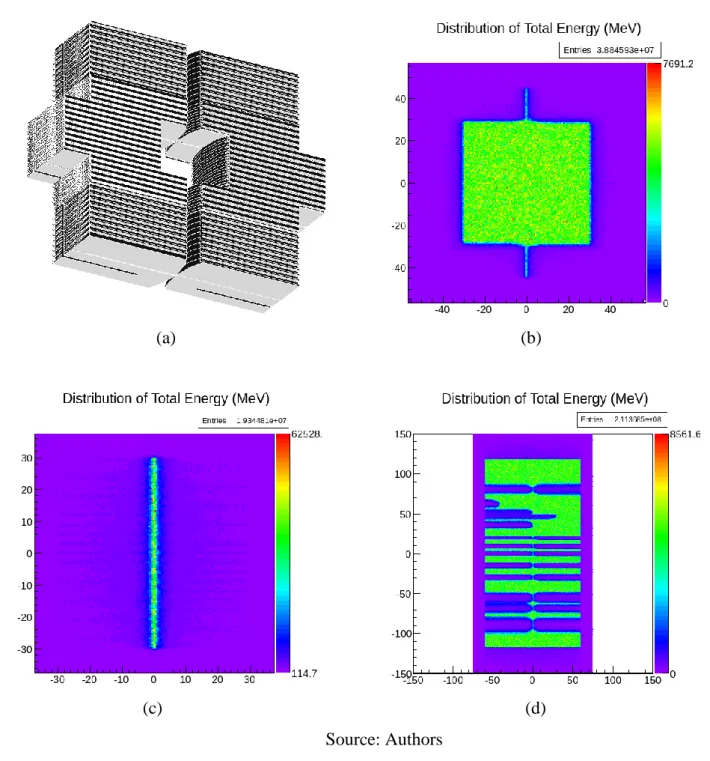
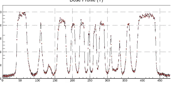
The Figure 3 shows the modeled MLC (a), the distributions of total energy in the phase space for the evaluation of penumbra (b), leakage (c) and tongue-and-groove effect (d). The Figure 4a shows the dose distribution in isodose regions for the evaluation of penumbra, at depth of 15 mm. The penumbra is the region defined between the region of 80% (yellow) and the region of 20% (blue), which distance is approximately 6 mm. The Figure 4b shows the dose profile in the axis Y for the evaluation of leakage, at X = 40 mm and depth of 50 mm. The Figure 5 shows the dose profile in the axis Y for the evaluation of tongue-and-groove effect, at X = -80 mm and depth of 15 mm.
Figure 3: Visualization of the modeled MLC defining a field of 10 × 10 cm2 (a) and distribu-tions of energy for the evaluation of penumbra (b), leakage (c) and tongue-and-groove effect (d).
(a) (b)
(c) (d)
Figure 4: Dose distribution for the evaluation of penumbra (a) and profile of dose distribution
for the evaluation of leakage (b).
(a) (b)
Source: Authors
Figure 5: Profile of dose distribution for the evaluation of tongue-and-groove effect.
Visually, the dose distributions are similar to the results published by Heath and Seuntjens (2003). However, in a quantitative comparison, the results are different since the values of the dimensions of the leaves available in BEAMnrc Users Manual (ROGERS et. Al., 2011) are not representative of a real Varian Millennium 120-leaf. Furthermore, the leaf sides were not focused towards the target, as modeled in the BEAMnrc. For this, it is necessary to model each leaf sepa-rately. The vertexes related to the leaf sides must be determined according to the distance from the center (beam axis).
4. CONCLUSION
In this work, it was described a methodology for modeling MC of MLCs using code Geant4. The Varian Millennium 120-leaf MLC was modeled to exemplify this methodology.The results re-garding the dosimetric characteristics were qualitatively satisfactory. Thus, the described meth-odology can be used to model other MLCs in Geant4.
REFERENCES
CASTRO, A.; NGUYEN, B.; ALMEIDA, C. E. Determinação de parâmetros de Tongue and Groove de colimadores de multilâminas. Revista Brasileira de Física Médica, 6 (2), 2012. HEATH, E.; SEUNTJENS, J. Development and validation of a BEAMnrc component module for accurate Monte Carlo modelling of the Varian dynamic Millennium multileaf collimator.
Physics in Medicine and Biology, 48, 2003.
JANG, S. Y.; VASSILIEV, O. N.; LIU, H. H.; MOHAN, R. Development and commissioning of a multileaf collimator model in Monte Carlo dose calculations for intensity-modulated radiation therapy. Medical Physics, 33(3), 2006.
JERAJ, M.; ROBAR, V. Multileaf Collimator in Radiotherapy. Radiology and Oncology, 38(3), 2008.
LOVEROCK, L. Linear Accelerators. In: MAYLES, P.; NAHUM, A.; ROSENWALD, J.C. (Org.). Handbook of Radiotherapy Physics: Theory and Practice. Inglaterra: Taylor & Fran-cis, p.197-240, 2007.
OKAMOTO, H.; FUJITA, Y.; SAKAMA, K.; SAITOH, H.; KANAI, T.; ITAMI, J.; KOHNO, T. Commissioning of 6 MV medical linac for dynamic MLC-based IMRT on Monte Carlo code GEANT4. Radiol Phys Technol, 7, 2014.
OLIVEIRA, A. C. H. ; VIEIRA, J. W. ; SANTANA, M. G. ; LIMA, F. R. A. Monte Carlo Simu-lation of a Medical Linear Accelerator for Generation of Phase Spaces. In: International
Nucle-ar Atlantic Conference - INAC, Recife. 2013 International NucleNucle-ar Atlantic Conference -
INAC 2013, 2013.
ROGERS, D. W. O.; WALTERS, B.; KAWRAKOW, I. BEAMnrc Users Manual. Ottawa: National Research Council of Canada, 2011. Pag. 172-204.
TACKE, M. B.; SZYMANOWSKI, H.; OELFKE, U.; SCHULZE, C.; NUSS, S.; WEHRWEIN, E.; LEIDENBERGER, S. Assessment of a new multileaf collimator concept using GEANT4 Monte Carlo simulations. Medical Physics, 33 (4), 2006.
TYAGI, N.; MORAN, J. M.; LITZENBERG, D. W.; BIELAJEW, A. F.; FRAASS, B. A.; CHETTY, I. J. Experimental verification of a Monte Carlo-based MLC simulation model for IMRT dose calculation. Medical Physics, 34 (2), 2007.
VERHAEGEN, F.; SEUNTJENS, J. Monte Carlo modelling of External Radiotherapy Photon Beams. Physics in Medicine and Biology, 48, 2003.
VIEIRA, A. M. M. Dosimetria dos Sistemas de Radiocirurgia Estereotáxica com
Aceleradores Lineares Equipados com Colimadores Micro Multi-lâminas. Tese de