A Comprehensive Method for the Modeling of
Axial Air-gap Eccentricities
in Induction Motors
A. Ghoggal, M. Sahraoui, S.E Zouzou.
Abstract— When speaking about the diagnostic and reliability of induction motor (IM), it is important to note that the modeling is a main step permitting to study the evolution laws of the faults related harmonics. This is the aim of many previous works, but only few attempts on axial air-gap eccentricity modeling can be found. This paper deals with a new model of axial air-gap eccentricity faults in IM. This model is based on a variant of the modified winding function approach (MWFA) which allows the axial nonuniformity to be taken into account by considering that the eccentricity levels rise linearly along the rotor shaft. The model proves very useful to study the most documented IM faults without any need for Fourier series developments of turns and permeance functions in case of axial eccentricity. Knowing that the skew factor can be applied only under axial air-gap uniformity, the proposed model offers an accurate way in order to include the slots permeance and skewing effects even under axial eccentricity. The analysis is completed by a simulation tests on a 2-pole IM.
IndexTerms— Induction motor, space harmonics, skew, slot
permeance effect, axial air-gap eccentricity.
I. INTRODUCTION
Nowadays, three-phase squirrel cage induction motors are omnipresent in industrial and manufacturing processes. This is mainly due to their low cost, reasonable size, ruggedness and ease of control. Usually, the IMs work under many stresses from various natures (thermal, electric, mechanical and environment) which can affect their lifespan by involving the occurrence of stator and/or rotor faults leading to unscheduled downtime. Therefore, one can reduce significantly the maintenance costs by preventing sudden failures in IM. This is the main goal of the operator of electrical drives.
Most of faults in three-phase IMs have relationship with air-gap eccentricity which is the condition of the unequal air-gap between the stator and the rotor
.
This fault can result from variety of sources such as incorrect bearing positioning during assembly, worn bearings, a shaft deflection, and so on. In general, there are two forms of air-gap eccentricity: radial (where the axis of the rotor is parallel to the stator axis) and axial. Each of them can be static (where the rotor is displaced from the stator bore centre but is still turning upon its ownaxis) or dynamic eccentricity (where the rotor is still turning upon the stator bore centre but not on its own centre).
Manuscript received Augest 9, 2008. This work was supported by the Laboratory of Electrical engineering of Biskra (LGEB) – University of Biskra- BP 145 – 07000 Biskra - Algeria.
A. Ghoggal, M. Sahraoui and S.E. Zouzou are with the Laboratory of Electrical engineering of Biskra (LGEB) (e-mail: [email protected], [email protected], [email protected]).
.
In order to develop improved methods to diagnose stator and rotor faults, extensive research has been done on the dynamic modeling of the IM in both healthy and faulty states. Numerous IM model are based on the MWFA in order to account for the air-gap eccentricity. The principal related spectral frequencies are derived from the general equation given in [1] and expressed as follow
(
)
sd b dyn
RSH s f
p n N
f ⎥⋅
⎦ ⎤ ⎢
⎣ ⎡
± − ⎟⎟ ⎠ ⎞ ⎜⎜
⎝ ⎛ ± =
+ 1 1 (1)
In healthy state and static eccentricity, the called principal slot harmonics PSH are obtained for . In case of dynamic eccentricity,
0
=
d n ...
, ,
nd =12 . If both types coexist, in the low range frequency appear the harmonics of the mixed eccentricity described by [2]
r s mix f k.f
f = ± , (2) with k=1,2,3,...
In order to reduce torque and speed ripples due to the slot harmonics, it is usually recommended to use skewed rotor and/or stator slots. In this context, the skewing of the rotor bars was modeled in [2] and [3] thanks to the well known skew factor, whereas the authors of [4] use the definition of the inductance per unit of length.
vibration were dependent on the bearing stiffness and that the rotor vibration in large induction motors will principally consist of its radial rigid translation or rotation. Besides, it was verified that these modes can be considered as a mixture of dynamic and static axial eccentricity which make indispensable the search of a good model of the air-gap permeance function.
An effort to extend the MWFA to consider the axial nonuniformity for skew and air-gap eccentricity modeling was performed in [8] and later-on in [9]. It is interpreted as 2-D extension of the MWFA. Afterward, the rotor saliencies produced by the radial and axial air-gap eccentricity was employed in order to detect the fault from the zero sequence voltage [10]. In [3], a comprehensive study of the static axial eccentricity was performed. It was verified that static axial eccentricity demonstrates similar characteristics such as static radial eccentricity and can be recognized from the current spectrum, excluding the symmetric case to the midpoint of the motor shaft. It is important to note that none of the referred works analyzed all the possible cases of dynamic and mixed axial eccentricity. Furthermore, it should be noted that the use of the skew factor is limited to the inductance calculation when there is no axial asymmetry other than the slot skewing. In case of axial eccentricity, a new formalism is to be developed. These are what this paper attempts to elucidate.
II. EXPERIMENTAL CREATION OF RADIAL AND AXIAL ECCENTRICITIES
Referring to Fig. 1, and supposing that the eccentricity levels rise linearly along the rotor shaft for the same angular position, yield [11]
⎟⎟ ⎠ ⎞ ⎜⎜ ⎝ ⎛
− =
st s s
L z
z) 1
( δ0
δ (3)
⎟ ⎟ ⎠ ⎞ ⎜ ⎜ ⎝ ⎛
− =
dy d d
L z
z) 1
( δ 0
δ (4)
Fig. 1. Axial linear rise of the eccentricity level.
Note that, for fixed values of
δ
s0 andδ
d0, the choice ofL
st andL
dyidentifies the shaft misalignment level.The pure radial eccentricity is well documented previously. In practice, the most possibly case is that the non-uniformity depends from the rotor axial length. An important step in order to study the axial eccentricity is to explain its mechanism of reproduction. In static axial eccentricity, the
rotor rotates around its natural axis which is inclined compared to the stator one. In dynamic axial eccentricity, the rotor natural axis is inclined compared to its rotational axis which is superimposed to the stator one [16]. The combinations of these modes and those of pure radial eccentricity lead to variants of mixed axial eccentricity.
Fig. 2. Artificially created static eccentricity (a) and dynamic eccentricity (b) by fitting support parts.
The dynamic eccentricity can be forced by fitting a support parts or a thin eccentric bushing between the rotor shaft and the bearing of the front side [10], and with the same manner as for the other back side. The static eccentricity is obtained by fitting a non-concentric support between the bearing external surface and the bearing housing of the front and back sides of the motor as can be seen in Fig 2. Note that bearings must be replaced by others of bigger internal diameter in case of dynamic eccentricity, and a smaller external diameter in case of static eccentricity. Support parts with same thickness at the front and the back sides placed at the same angle from an axe of reference leads to pure radial eccentricity. When the support parts are of unequal thickness that lead to an axial eccentricity with Lst>l or/and Ldy>l. The third case is when
the support part of the back side is placed at 180° from that of the front side. That leads to axial eccentricity with Lst<l
or/and Ldy<l. If they are of equal thickness we obtain the
symmetric case to the midpoint of the motor shaft. Even though the described procedure remain an artificial arrangement, similar effects can be reproduced in reality because of many factors such as inadequacies machining, mechanical or thermal deformations or/and stresses of different origins.
III. TRANSIENT MODEL OF THE IM
The multi-loops model supposes that the squirrel cage is composed of identical and equally spaced rotor loops. Thus, the current in each mesh of the rotor cage is an independent variable. By supposing that there are no inter-bar currents, no eddy currents, saturation and winding losses, and that the permeance of the iron is infinite, the voltage and mechanical equations of the loaded IM for a three-phase stator winding YN-connected (grounded neutral) can be written as
[ ] [ ][ ]
(
[ ][ ]
)
[ ] [ ] [ ]
⎪ ⎪ ⎩ ⎪⎪ ⎨ ⎧
= − − ∂
∂ =
+ =
dt d J f
C C I L I C
dt I L d I R U
r r r v r e r
T e
ω ω
θ . and .
.
.
(5)
[ ]
U corresponds to the system voltages,[
to the stator and rotor currents. They are]
I1 ) 4
(Nb+ × matrix. The resistances
matrix
[ ]
R and the inductances matrix[ ]
L are matrices. In Y-connection (floating neutral), the system must be restructured as described in [12].) 4 ( ) 4
(Nb + × Nb +
IV. INDUCTANCES CALCULATION A. Global Formulation
The 2-D modified winding function (MWF) can be expressed as in [8].
∫∫
− −〉 〈 − = π ϕ θ ϕ θ ϕ π θ ϕ θ ϕ 2 0 0 11 ( , , ). ( , , )
2 1 ) , , ( ) , , ( l r r r r dzd z g z n g l z n z N (6) with ϕ θ ϕ π π d dz z g l g l
r). .
, , ( 1 2 1 2 0 0 1 1
∫ ∫
⋅⎜⎜⎝⎛ ⎟⎟⎠⎞ = −− (7)
By considering that the mean air-gap radius doesn’t change even in case of eccentricity, any variable defined originally with respect to φ, z and r, can be considered as a function of only φ and z. Then, the magnetic field in the air-gap is projected in a cylindrical surface of radius r0.Takingx=r0.ϕ and xr =r0.θr one can now envisage 2-D representation
where the skew and the crossing of rotor loops under the field of stator coils become more interpretable (Fig. 3) [16]. In this case, x correctly translates the linear displacement along the arc corresponding to the angular opening ϕ .
Knowing that N is the MMF per unit of current, the expression giving the inductance between any winding W2
and winding W1 is abridged to
. ) , , ( ). , , ( ) , , ( ) ( 1 2 2 0 0 1 0 1 . 2 0 dzdx x z x g x z x n x z x N x L r r W r r l W r W W − ⋅ =
∫ ∫
π μ (8)Using (6) and taking , a new
expression can be obtained
) , , ( ) , , ( 1 r
r P x z x
x z x
g− =
⎟ ⎟ ⎠ ⎞ ⎜ ⎜ ⎝ ⎛ 〉 〈 〉 〈 ⋅ 〉 〈 − ⎟⎟ ⎠ ⎞ ⎜⎜ ⎝ ⎛ 〉 〈 =
∑∑
= = P
n P n P n n P l r x
L W W
i j j W i W r W W 2 1 1 1 2 1 0 0 1 . 2 . . . . 2 ) ( υ ν μ π (9) where υ and are the number of coils of winding W1 and W2
respectively. Thus, according to the chosen type of winding, the mutual inductance between W1 and W2 depends on the
mutual inductances of their elementary coils. As a detailed example, one can use (9) to calculate the mutual inductance between stator coil
A
i and rotor loop rj. The rotor loop isregarded to be a coil with one turn ( =1 in equation (9)). Then: dzdx x z x P x z x n x n l r n n P r r r r l Ai rj Ai
j( , , ). ( , , )
). ( . 2 1 . . 0 2 0 0
0
∫ ∫
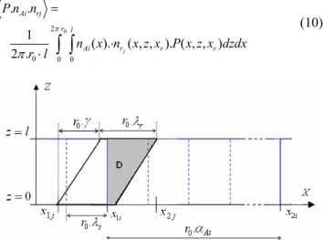
⋅ ⋅ = π π (10)
Fig. 3. 2-D representation of the crossing of rotor bars under the field of stator coils.
According to Fig. 4, for any rotor position , the distribution function of rotor loop r
r
x
1can be expressed in 2-D
as follow ⎩ ⎨ ⎧ 〈 〈 〈 〈 = Otherwise x z x z x z x x x x x 1 x z x n j j r j r j r rj 0 ). ( ) ( ) ( , ) ( ) ( ) , ,
( 1 2 1 2 (11)
Fig. 4. The 2-D distribution function of rotor loop rj for a known rotor
position.
The endpoints of rotor loops depend on xr because of the
rotor relative displacement. One can choose simply xjto
indicate xj(xr), and consider only the spatial coordinates x and z in the integral’s boundaries. As for and , they are defined as:
j 1
z z2j
(
)
(
) (
)
⎪⎩ ⎪ ⎨ ⎧ ≤ ≤ + − − + ≤ ≤ = j r j r j r j 1jj x x r , x r x x
r l r x x x , x z 2 0 1 0 1 0 0 1
1 . .
. 0
)
( λ λ
γ λ (12)
(
)
(
(
)
⎪⎩ ⎪ ⎨ ⎧ ≤ ≤ + + ≤ ≤ − = j j j j j j x x r x , l r x x x , x x r l x z 2 0 1 0 1 1 1 0 2 . . ) ( γ γγ
)
(13)where (x2j−x1j)=r0(γ +λr)
By means of (11), (10) becomes
dzdx x z x P x n l r n n P r x x x z x z Ai rj Ai j j j j ) , , ( ) ( 2 1 . . 2 1 2 1 ) ( ) ( 0
∫ ∫
⋅ ⋅
=
Following Fig. 5, and supposing that the MMF rise linearly across the slots of widthβ, the expression of the distribution function nAi for stator coil
A
i can be deduced. [4].Fig. 5. The turn function of coil Ai
(
)
(
(
)
(
(
)
))
(
)
(
(
)
)
⎪ ⎪ ⎪ ⎩ ⎪ ⎪ ⎪ ⎨ ⎧ ≤ ≤ + + − − + ≤ ≤ + + + ≤ ≤ − = Otherwise r x x r w r r w r x x r w x n Ai i Ai Ai Ai i Ai Ai 0 x x . x . . x x . x . x x x . ) ( 2i 0 1i 2 0 0 1i 0 1i 0 1i 1i 1 0 α β β α β β β β (15)According to (15), when the rotor loop is partially under the field of the stator coil, the integral in the external interval is null. Then, the integral of (14) becomes a double integral over 'D'
∫∫
= D r Ai rjAi n x P x z x dzdx
l r n
n
P ( ). ( , ,, )
2 1 . . 0 0
π (16)
where 'D' is the common surface (grey region in Fig. 3) among the surface of projection of rotor loop and that of stator coil . In general, the calculation of is similar to the calculation of the volume having the base 'D', and to the calculation of the area of 'D' itself in case of constant air-gap and a neglected slot width (β=0). Using the above relationships, one can obtain the integral of (16).
j r
i
A
Lr1AB- Uniform Air-Gap
As an example, and when neglecting the slot opening, is constant in 'D'. According to which is the aria of 'D', equation (16) can be written as
Ai n ) ( r D x S 0 0. 2 ) ( . . . g l r x S w n n
P Ai D r
rj
Ai = π . (17)
For this particular case and according to rotor loop positions yields ⎪ ⎪ ⎪ ⎩ ⎪⎪ ⎪ ⎨ ⎧ ≤ + + ≤ ≤ ≤ ≤ ≤ ≤ = Otherwise x r , S r x r x S r x r ), x ( S r x 0 ), x ( S x S r r D r r r r D3 r r r D2 r r D1 r D , 0 ). ( ). ( . ), ( . . . ) ( 0 4 0 0 0 0 0 λ γ λ γ λ λ γ γ (18) with 1 0
0. ( 1). .
). 1
( r s i
r
r x j r i r x
x = + − α − − α − (19) and
{
}
{
}
{
}
⎪ ⎪ ⎩ ⎪ ⎪ ⎨ ⎧ = + = + − − + = − + = = .l . r r S S r x S r S r S x S l r x r S ) x ( S x . ) . (2.r l ) x ( S r 0 r D D r r D1 r D D1 r D3 r D1 r D2 2 r 0 r D1 λ λ γ λ γ λ γ γ γ γ 0 3 4 0 0 2 0 0 0 ). ( ) .( ) . ( ) . ( ) ( ). . ( ) .( (20)
Then, the slot skewing is perfectly modelled thanks to the plane representation of the crossing of rotor loops under the field of stator coils. Therefore, no need for the known skew factor and Fourier series development of the turns and winding function. Regarding P.nA and P.nrj , and due to
the fact that they are independent from rotor position , their values are easily deduced from the two expressions:
r
x
0
.n n
P A = A
g (21) 0 . 1 . g N n P b
rj = (22)
Knowing that dxr =r0.dθr and that the derivatives of (21)
and (22) are null, yield
⎟⎟ ⎠ ⎞ ⎜⎜ ⎝ ⎛ = =
∑
= υ μθ 0 1
0 .. 0 .. ( ) . . ( ) . ) ( i r r D Ai 0 r r rj A r r rj A dx x dS w g r dx x dL r d x
dL (23)
Following the same procedures, it will be possible to find all inductances and their derivatives. Note that the resulting algorithm is easily adaptable to any winding. In the same manner, one can integrate the linear rise of the MMF across the slot; in this case, the surface area will be replaced by a volume calculation.
C. Radial eccentricity
In case of eccentricity, the air-gap function is given by [2]
(
)
(
[
0 0]
0.1 ( ).cos / ( ).cos( )/
) , , ( r x x z r x z g x z x g r d s r − − −
)
= δδ (24)
In general, numerical calculation makes it possible to find the machine inductances using (9). However, an expansion in Fourier series of P using the first p harmonics can be used to get an analytical solution [13]. Then, in case of pure radial eccentricity
(
[
∑
= − + = p 1 i r 0 i 0r P.cosi.x/r ρ x
2 P x x
P( , ) ( )
)
]
(25) and i 2 2 0 i δ δ 1 1 δ 1 g 1 2.P ⎟⎟
⎠ ⎞ ⎜ ⎜ ⎝ ⎛ − − ⋅ ⎟ ⎟ ⎠ ⎞ ⎜ ⎜ ⎝ ⎛ −
= (26)
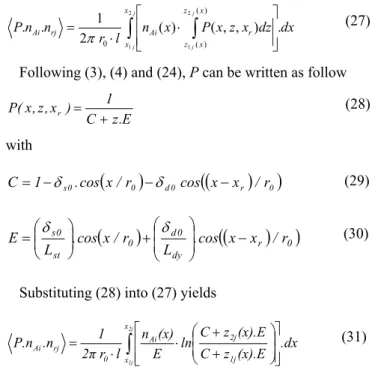
with δand ρ are function of δs,δd and θras described in [2]. D- Axial eccentricity
If the double integral leading to the inductance value in case of axial eccentricity will be difficult or we won't even be able to evaluate it, it can be facilitated by using a proper numerical integration to convert the integral into a simple some of terms. The proposed method is based on a
dx dz x z x P x n l r n
n P
j
j
j
j x
x
x z
x z
r Ai
rj
Ai ( ) ( , , ) .
2 1 .
.
2
1
2
1
) (
) (
0
∫
∫
⎥⎥ ⎦ ⎤ ⎢
⎢ ⎣ ⎡
⋅ ⋅
=
π (27)
Following(3), (4) and (24), P can be written as follow
E . z C
1 ) x , z , x (
P r
+
= (28) with
(
0)
d0(
(
r)
0)
0
s .cos x/r cos x x /r
1
C= −δ −δ − (29)
(
)
(
(
r)
0dy 0 d 0 st
0 s
r / x x cos . L r / x cos . L
E ⎟⎟ −
⎠ ⎞ ⎜ ⎜ ⎝ ⎛ + ⎟⎟
⎠ ⎞ ⎜⎜ ⎝ ⎛
= δ δ
)
(30)Substituting (28) into (27) yields
.dx (x).E z C
(x).E z C ln E
(x) n l r 2π
1 .n
P.n
2j
1j x
x 1j
2j Ai
0 rj
Ai
∫
⎥ ⎥ ⎦ ⎤ ⎢
⎢ ⎣ ⎡
⎟ ⎟ ⎠ ⎞ ⎜
⎜ ⎝ ⎛
+ + ⋅ ⋅
= (31)
At this stage, a simple numerical integration instead of double integration could be used to evaluate (31). If there is another axial dependency (like air-gap variation due to the slot permeance effects accounting for the skew), it should be remembered that the use of a double numerical integration in order to calculate (16) remain the obvious alternative. Note that, unlike the few attempts denoted in section I, the proposed solution considers all the harmonics of the inverse of air-gap function. This may lead to more accurate signal spectra, especially, in the study of IMs having a large number of poles. Furthermore, a considerable decreasing on the time and calculation process can be obtained thanks to the reduction of the double numerical integration into one simple integration.
V. SIMULATION RESULTS A. Inductances Calculation
The studied machine is a three-phase 2-pole star connected 3kW IM. The skew of rotor bars is taken into account in the simulation as well as the linear rise of the MMF across the stator slots. However, the slot effects may not be very important according to the study of [14]. Average core saturation effect can be included as described in [15]. The particularity of the MWFA is that it can evaluate these effects individually and in a relatively short computation time compared to finite element methods. Even as the above analysis makes a number of simplifying postulation, it identifies the important frequency components one would expect to detect in the stator current spectra.
Fig. 6. Self inductance of stator winding A in dynamic radial eccentricity of 20% (dot line), 40% (dash line) and 60% (solid line)
In both static radial and static axial eccentricity, the self and mutual inductances of the stator windings will be independent of the rotor position. However, they will change with respect to the rotor position in case of dynamic eccentricity (Fig. 6). In case of axial eccentricity, their absolute values increase when the coefficient corresponding to the position of the concentric cross section of the rotor (Ldy)increases. A huge value of Ldy (like 1 m and more) leads
to pure radial eccentricity (Fig.7 and 8).
Fig. 7. Self inductance of stator winding A in dynamic axial eccentricity of
0 d
δ =60%, and =0.5xl...2xl
dy L
Fig. 8. Mutual inductance between stator winding A and Bin dynamic axial eccentricity of
0 d
δ =60%, and =0.5xl...2xl
dy L
Fig. 9. Mutual inductance between the first and the second rotor loop in static radial eccentricity of 20% (dot line), 40% (dash line) and 60% (solid line)
the first and second rotor loop as a function of and the rotor position.
st
L
Fig. 10. Rotor mutual inductance between the first and second rotor loop in static axial eccentricity of
0 s
δ =50% and =0.5xl...2xl
st L
Fig. 11. Mutual inductance between stator winding A and rotor loop r1 in
dynamic axial eccentricity of
0 d
δ =70% for different values ofLdy.
Fig. 12. Mutual inductance between stator winding A and rotor loop r1 in
static axial eccentricity of
0 s
δ =50% for different values of
L
st.The effect of dynamic axial eccentricity in the variation of mutual inductance with respect to the rotor angular position (from 0 to 2π) and the degree of shaft misalignment ( from half l to 2.5xl) is shown in Fig. 11. It can be seen
that the inductances for an axial eccentricity case describe the same characteristic of radial eccentricity whose level is the average value of the eccentricity levels at the two ends of the machine in the actually axial eccentricity. Hence, one can
predict that the fault- related harmonics would become undetectable for the case with average zero dynamic eccentricity (
A r
L
1dy
L
2 /
l
Ldy = ). The same analysis as for the static axial eccentricity and Fig. 12.
B- Integration of the slot permeance effect
For including the slot permeance effect, additional terms must be added to (9). It reflects the air-gap variation due to the doubly slotting. We attempt here to suggest a simple way which profits of the proper potentiality of the MWFA and the actual advance in computer hardware and software. After some improvements, this may be considered as an alternative of methods based on Fourier series development. The air-gap length in case of skewed rotor slots is
) , ( ) , , ( ) , , (
) , , (
r ss r rs r e
r
x x g x z x g x z x g
x z x g
+ +
=
(32)
where is the air-gap length without slotting effect. and are the additional terms due to rotor and stator slotting effects respectively. Then, one can define
e
g
rs
g
g
ssx
andr
x
asr
n
x
x
=
−
.
λ
(33)r r
r x ztg n
x =( − . (γ))− .λ (34)
Fig. 13. air-gap variation due to rotor slotting effect
If the quotient
x
/
λ
r is within roundoff error of an integer, then n is that integer. In MATLAB software, this can be done using the function mod so that x=mod(x,λr) and similarlyxr =mod(xr −z.tg(γ),λr).According to Fig. 13,
g
rscan be defined as follow - If xr ≤(λ −r βr)⎩ ⎨
⎧ ≤ ≤ + =
otherwise
0
) x ( x x )
, ,
( r r r r r
rs
h x z x
g β (35)
-Else (Ifxr ≥(λ −r βr))
{
}
⎩ ⎨
⎧ ≤ ≤ − − ≤ ≤
=
otherwise
0
x
x and ) ( x
0
) , , (
r
r r r r
r r rs
x h
x z x g
λ λ
β (36)
As for , it is easily obtained from the following expression
ss
g
⎩ ⎨
⎧ ≤ ≤
=
otherwise
0
x ` 0 )
,
( r s λs
rs
h x x
g (37)
with `x=mod(x,λs)
Fig. 14 depicts the stator-rotor mutual inductance plot in axial air-gap eccentricity condition including stator and rotor slots permeance effect.
Fig. 14. Mutual inductance between stator winding A and rotor loop r1 in
static axial eccentricity of
0 s
δ =60% and
L
st=
l
C. Dynamic SimulationThe next simulation results predict the current spectra when the motor is fed from a sine wave symmetrical voltage supply. Based on the IM model described above. The numerical simulation of the transient startup is performed. The frequency spectra of line current are obtained thanks to the Fast Fourier Transform (FFT) using a Hanning’s window. It is drawn in the logarithmic magnitude scale and normalized format. The magnitude of the fundamental is assigned to the value of 0 dB. In all simulation, 75% of the full load is applied.
1) Radial eccentricity
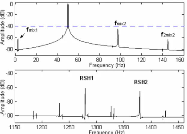
Fig. 15 represents the line current spectra of the studied IM operating in mixed radial eccentricity condition. The stator winding is YN-connected. In the low range frequency, it is possible to see the mixed eccentricity components of equation (2).
Fig. 15. Simulated stator current spectra in case of mixed radial eccentricity of and , stator winding YN-connected. Low frequencies (top), high frequencies (bottom).
% 20
=
s
δ δd0=20%
It is clear that the lower RSH associated to a triplen pole pair appears obviously with the upper one even under balanced power supply (Fig 15) in Y-N connection [9]. As predicted, when we consider the Y-connection, only the highest RSH associated to nontriplen pole pair can be seen, while the two RSHs are generated when considering 5% of supply unbalance (Fig. 16) [2]. In addition, one can note that
the dynamic eccentricity harmonics are very weak; this is due mainly to the skew effect.
Fig. 16. High rang frequency of simulated stator current spectra in case of mixed radial eccentricity δs=20% and =20%
d
δ , stator winding Y-connected. Balanced supply (top), 5% of supply unbalance (bottom).
2) Axial eccentricity
Fig. 17 depicts the rotational speed and electromagnetic torque from startup to steady state of the studied IM operating in mixed axial eccentricity conditions compared with the case of mixed radial eccentricity. Load is applied after 0.7 s. The considered axial eccentricity has a static radial eccentricity component of 20% and dynamic axial eccentricity of
% 20
0 = d
δ
with Ldy =l. One can note that the axial air-gap nonuniformity modifies the transient startup as well as the slip in steady state.Fig. 17. Speed (top) and electromagnetic torque (bottom) in mixed eccentricity conditions of and . Pure radial eccentricity (solid line), axial eccentricity with (dot line).
% 20
=
s
δ δd0=20%
l Ldy=
The corresponding line current spectra are shown in Fig 18. As it is clear, the amplitudes of the characteristic components of equation (2) under the same load condition and the same level of eccentricity backside the machine as in pure radial eccentricity (Fig. 15) decrease. As shown in Fig. 19 and Fig. 20, In case of average zero dynamic eccentricity
% 20
0 =
δ with (Ldy =l/2) and δs=20%, and average
zero static eccentricity δ0 =20% with ( Lst =l/2 )
Consequently, we can state that axial eccentricity with low average value (especially when Ldy<l or/ and Lst<l) but high value backside of the rotor can be confused with a radial eccentricity having a small fault level. So, in order to make a reliable diagnosis of radial eccentricity, one must be sure that its variation has no axial dependency.
Fig. 18. Simulated stator current spectra in case of mixed axial eccentricity of
% 20
=
s
δ radial and 20%
0= d
δ axial with , stator winding YN-connected. Low frequencies (top), high frequencies (bottom).
l Ldy =
Fig. 19. Simulated stator current spectra in case of mixed axial eccentricity of δs =20% radial and δd0=20% axial with . Stator winding YN-connected. Low frequencies (top), high frequencies (bottom).
2 /
l Ldy =
Fig. 20. Simulated stator current spectra in case of mixed axial eccentricity of %
20
0= s
δ axial withL l/2, and
st= δd =20%radial. Stator winding
YN-connected. Low frequencies (top), high frequencies (bottom).
V. CONCLUSION
In this work, an accurate mathematical model for three-phase induction motor working under radial and axial air-gap eccentricity was presented. This model was based on the multiple-coupled circuits approach. The authors have proposed an improved technique in order to calculate the motor inductances using an extension in 2-D of the MWFA which make possible to consider any axial no-uniformity including the slots skewing and permeance effects. Other effects likethe linear rise of the MMF across the stator slots were also considered. Using this technique, the resulting inductances expressions were less complicated and more suitable to be implemented in algorithm. The different types of the axial eccentricity were successfully modeled taking into account that the eccentricity levels rise linearly along the rotor shaft. The simulation tests which were carried out on a 3kW, 2-poles induction motor, confirm that the axial eccentricities have the same signatures in the stator current spectra as the radial eccentricities. On the other hand, it was found that a non-inspected presence of an axial non-uniformity of the air-gap in addition to the radial eccentricity reduce the amplitudes of the known fault related harmonics which decrease the reliability of the diagnosis process of radial eccentricity.
APPENDIX - Nomenclature
A,B,C Windings of stator phases As, Bs and Cs respectively
LW2.W1 Mutual inductance between any winding W1 and W2 of the motor
l Rotor length
w Number of turns per coil Nb Number of rotor bars
Ne Number of stator slots
Lb Rotor bar leakage inductance
Le End-ring leakage inductance
Rs Stator phase resistance
Rb Rotor bar resistance
Re End-ring resistance
γ Mechanical angle of the skew λs Pitch of the stator slots
λr Pitch of the rotor slots α Opening of the coil (coil pitch)
β Stator slot width (opening)
θr Rotor angular position
N Modified winding function n Distribution function (turns function) F The magnetomotive force
fs The main frequency (Fundamental frequency)
fr Rotational frequency
s Slip in per unit
p Number of fundamental pole pairs nd Index of dynamic eccentricity
0 Permeability in vacuum δs Static eccentricity level δd Dynamic eccentricity level δ Global eccentricity level
δs0 Static eccentricity level backside of the rotor (z=0) δd0 Dynamic eccentricity level backside of the rotor (z=0)
Lst ,
Ldy
Position of the concentric cross section of the rotor in static and dynamic axial eccentricity respectively
C Electromagnetic torque
Cr Load torque
Jr Moment of inertia
fv Viscous friction
ωr Mechanical speed of the rotor
g0 Average air-gap length
g Air-gap function
P Inverse of air-gap function (permeance function of air-gap) r Average radius of the air-gap (a polar radius)
r0 Average radius of the air-gap in symmetrical condition
rj The jth rotor loop
REFERENCES
[1] J.C. Cameron, W.T. Thomson and A.B Dow, “Vibration and current monitoring for detecting air-gap eccentricity in large induction motors,” IEE, vol.133, no.3, 1986; pp.155-163.
[2] S. Nandi, R.M. Bharadwaj and H.A. Toliyat, “Performance analyses of three-phase induction motor under mixed eccentricity condition,”. IEEE Trans. on Energy Conv. vol.17, no. 3, 2002; pp.392-399.
[3] X. Li, Q. Wu and S. Nandi, “Performance analysis of three-phase induction machine with inclined static eccentricity,” IEEE Trans. on Ind. App. vol.43, no. 2 2007, pp. 531-541.
[4] M.G. Joksimovic, D.M. Durovic and A.B. Obradovic, “Skew and linear rise of MMF across slot modeling-winding function approach,” IEEE Trans. on Energy Conv. vol. 14, no. 3, pp. 315-320.
[5] A. Tenhunen, T. Benedetti, T.P. Holopainen and A. Arkkio, “Electromagnetic forces in cage induction motors with rotor eccentricity,” In Proceeding of IEMDC 1-4 June 2003, pp. 1616-1622.
[6] H.M. Kelk, A. Eghbali, H.A. Toliyat., “Modeling and analysis of cage induction motors under rotor misalignment and air gap eccentricity,” In Proceeding of IEEE IAS, 2-6 Oct. 2005, pp. 1324-1328.
[7] Cabanas MF, Melero MG, Aleixandre JG, Solares J. Shaft misalignment diagnosis of induction motors using spectral analysis: A theoriticl pproach. In: Proceeding of. ICEM Vigo, Spain, 1996. [8] G. Bossio, C.D. Angelo, J. Solsona, G. García and M.I. Valla, “A
2-D Model of the induction machine: Extension of the modified winding function approach,” IEEE Trans. on Energy Conv. vol. 19, no. 1, 2004, pp.144-150.
[9] A. Ghoggal, A. Aboubou, S.E. Zouzou, M. Sahraoui and H. Razik, “Considerations about the modeling and simulation of air-gap eccentricity in induction motors,” In Proceeding of IEEE IECON 06-10 Nov. 2006, pp. pp.4987-4992.
[10] G. Bossio, C.D. Angelo, J. Solsona, G.O. García and M.I. Valla, “Application of an additional excitation in inverter-fed induction motors for air-gap eccentricity diagnosis,” IEEE Trans. on Energy Conv. vol. 21, no. 4, pp. 839-847.
[11] A. Ghoggal, M. Sahraoui, A. Aboubou, S.E. Zouzou, H. Razik, “An Improved Model of the Induction Machine Dedicated to Faults-Detection - Extension of the Modified Winding Function,”. In Proceeding of IEEE ICIT 2005, Hong-Kong, China, 14-17 Dec. 2005, pp.191-196.
[12] L. Heming, S. Liling and X. Boqiang, “Research on transient behaviors and detection methods of stator winding inter-turn short circuit fault in induction motors based on multi-loop mathematical model,” In Proceeding of IEEE ICEMS, 27-29 September 2005, pp.1951 – 1955.
[13] J. Faiz and I.T. Ardekanei, “Extension of winding function theory for nonuniform air-gap in electric machinery,” IEEE Trans. on Magn. vol.38, no. 6, 2002; pp. 3654-3657.
[14] S. Nandi, “Modeling of induction machines including stator and rotor slot effects,” IEEE Trans. on Ind. App. vol. 40, no. 4, 2004, pp. 1058-1065.
[15] S Nandi, “‘A detailed model of induction machines with saturation extendable for fault analysis”, IEEE Trans. on Ind. App. vol. 40, 2004, pp.1302-1309.
[16] A. Ghoggal,S.E. Zouzou, H. Razik, M.Sahraoui, A. Khezzar, “ An improved model of induction motor for diagnosis purposes – Slot skewing effect and air-gap eccentricity faults”, Article in press,
Energy Conversion and Management (2009), doi:10.1016/ j. enconman.2009.01.003