In Situ
Analysis of a Silver
Nanoparticle-Precipitating
Shewanella
Biofilm by Surface
Enhanced Confocal Raman Microscopy
Gal Schkolnik1,2,3*, Matthias Schmidt3, Marco G. Mazza1, Falk Harnisch2, Niculina Musat3
1Department of Dynamics of Complex Fluids, Max Planck Institute for Dynamics and Self-Organization, Göttingen, Germany,2Department of Environmental Microbiology, Helmholtz Centre for Environmental Research, Leipzig, Germany,3Department of Isotope Biogeochemistry, Helmholtz Centre for
Environmental Research, Leipzig, Germany
Abstract
Shewanella oneidensisMR-1 is an electroactive bacterium, capable of reducing extracellu-lar insoluble electron acceptors, making it important for both nutrient cycling in nature and microbial electrochemical technologies, such as microbial fuel cells and microbial electro-synthesis. When allowed to anaerobically colonize an Ag/AgCl solid interface,S.oneidensis has precipitated silver nanoparticles (AgNp), thus providing the means for a surface
enhanced confocal Raman microscopy (SECRaM) investigation of its biofilm. The result is thein-situchemical mapping of the biofilm as it developed over time, where the distribution ofcytochromes, reduced and oxidized flavins, polysaccharides and phosphate in the undis-turbed biofilm is monitored. Utilizing AgNp bio-produced by the bacteria colonizing the Ag/ AgCl interface, we could perform SECRaM while avoiding the use of a patterned or rough-ened support or the introduction of noble metal salts and reducing agents. This new method will allow a spatially and temporally resolved chemical investigation not only ofShewanella biofilms at an insoluble electron acceptor, but also of other noble metal nanoparticle-precipi-tating bacteria in laboratory cultures or in complex microbial communities in their natural habitats.
Introduction
Shewanellaspecies are gram-negative facultative anaerobes, members of the class of electroac-tive bacteria, also known as exoelectrogens [1]. Electroactive bacteria can reduce extracellular insoluble electron acceptors (IEA), such as insoluble metal oxides and positively poised elec-trodes, as part of their respiratory chain [1–7]. They are therefore very important for metal cycling in nature, as they transform insoluble minerals, such as Fe2O3, into bioavailable ones,
such as Fe(II) [4,5,7–12]. Recent fascination with electroactive bacteria has, however, stemmed from their emerging use as living catalysts in microbial electrochemical technologies (METs), such as microbial fuel cells (MFC) and microbial electrosynthesis (MES). In primary METs an a11111
OPEN ACCESS
Citation:Schkolnik G, Schmidt M, Mazza MG, Harnisch F, Musat N (2015)In SituAnalysis of a Silver Nanoparticle-PrecipitatingShewanellaBiofilm by Surface Enhanced Confocal Raman Microscopy. PLoS ONE 10(12): e0145871. doi:10.1371/journal. pone.0145871
Editor:A Al-Ahmad, University Hospital of the Albert-Ludwigs-University Freiburg, GERMANY
Received:September 14, 2015
Accepted:December 9, 2015
Published:December 28, 2015
Copyright:© 2015 Schkolnik et al. This is an open access article distributed under the terms of the
Creative Commons Attribution License, which permits unrestricted use, distribution, and reproduction in any medium, provided the original author and source are credited.
Data Availability Statement:The pure proxy component spectra, and the raw image scan data for days 6, 9 and 35 are available under the following link:http://datadryad.org/review?doi = doi:10.5061/ dryad.8sc52.
electroactive biofilm is formed on an electrode, to be utilized for electricity production, waste-water purification, waste-water desalination or the synthesis of chemicals such as alcohols, organic acids and fuels [1,13–16].
In oxygen-depleted environmentsShewanella oneidensisMR-1, a frequently investigated Shewanellastrain, can not only respire soluble electron acceptors, such as nitrate, Dimethyl sulfoxide (DMSO), fumarate and soluble metal ions [17], but also transfer its terminal respira-tory electrons outside its outer membrane [6,9,11]. To do so, it employs three mechanisms: multi-hemecytochromes, nanowires and self-secreted electron transfer mediators (flavins) [18–
23]. Of particular interest for this work are multi-hemecytochromes, which transfer respiratory electrons from the metabolic chain to adjacent bacteria, biofilm elements or the solid interface [23–27]. Lately it has emerged that these electron transfer cascades are flexible and that many of the involved components can play the role of a terminal electron donor [17,23,28]. Unlike other electroactive species,Shewanella spp. also produce and secrete flavins [23,27,29,30], which serve for electron cycling between the bacteria and the IEA. Reduced flavins are secreted, transported to the IEA and become oxidized. Oxidized flavins can then be transported back to the bacterium and accept more respiratory electrons [30,31]. Flavins are also cofactors of cer-tain multi-hemecytochromes[23,32–34] and of other biomolecules [35,36]. They have also been reported to help solubilize IEA [37,38] and to serve as chemotaxis agents forShewanella [39]. Therefore, flavins are expected to be particularly pertinent components for theShewanella biofilm. As any other bacterial biofilm,Shewanellabiofilms are also composed not only of cells, but to a great extent of extracellular polymeric substance (EPS), the main structural compo-nents of which are polysaccharides [40,41]. Alginate has been shown to be a common polysac-charide in EPS of wastewater bacterial communities [42], such as the gram-negative
Pseudomonas aeruginosa[43]. It has been used before as a model EPS constituent for Shewa-nellacultivation [44]. Apart from polysaccharides, EPS in general andShewanellaEPS in par-ticular have also been shown to containcytochromes, flavins and nucleic acids [40,45].
One of the noteworthy properties of electroactive bacteria in general, and ofShewanella spp. in particular, is that they can precipitate silver nanoparticles (AgNp) when supplied with solu-ble silver salts in their growth medium [46,47], while still growing in spite of AgNp toxicity [47,48]. Noble metal nanoparticles, such as AgNp, can be used for Surface enhanced Raman spectroscopy (SERS), enhancing the Raman signal by up to six orders of magnitude in their immediate vicinity [49,50]. According to the SERS surface selection rules, only vibrational modes perpendicular to the particle surface become enhanced [49,50]. The enhancement is effective up to ca. 2 nm distance from the metal particle surface [49,50]. Silver or gold nanopar-ticles (AuNp) and roughened surfaces have become increasingly popular for use in SERS of biological samples, including both macromolecules [51–55] and whole cells [46,55–60]. Roughened Ag electrodes and AgNp/AuNp patterned microscope slides have been used as sup-port for protein immobilization, cell deposition and biofilm growth [51–53,56,61,62]. Using a roughened or patterned support provides great surface selectivity, but results in the loss of accessibility to other areas in the vertical sample axis. An alternative approach for the investiga-tion of bacteria and biofilms is to add soluble Ag(I) ions (e.g. in the form of AgNO3) to the
growth medium, followed by a reducing agent, such as borohydride or citrate [57,59,60]. Thus AgNp are formed in the solution, in the biofilm, inside bacteria and on their outer membranes, providing Raman enhancement in different regions of the sample according to AgNp distribu-tion [42,57]. It has been shown before that in some cases certain biomolecules, notably flavins, dominate the resulting signal [57,60,63], due to either adsorption of such molecules onto AgNp, or the location of AgNp precipitation, depending on the procedure employed. In order to clarify which biofilm components have contributed to the resulting spectra, some workers have acquired SERS spectra of the expected pure components under the same experimental
Planck Society, no funding number (http://www.mpg. de/en); and the Helmholtz Centre for Environmental Research, no funding number (http://www.ufz.de/). The funders had no role in study design, data collection and analysis, decision to publish, or preparation of the manuscript.
conditions used for analyzing biological samples, and later compared the pure component spectrum to the biological sample spectrum [55,57], an approach that we shall also employ here.
In Confocal Raman microscopy (CRM), as in other types of confocal microscopy (see e.g. [64,65]), light reflected or scattered by the sample has to pass through a pinhole to be detected, thus providing spatially accurate detection, eliminating noise from positions outside the focal plane and improving lateral resolution beyond the light diffraction limit [66,67]. CRM com-bines confocal microscopy with Raman spectroscopy, resulting in an image where each pixel consists of a Raman spectrum. Summing over certain frequencies in the Raman spectra, one can preferentially detect specific vibrational transitions of interest in the image. Like SERS, CRM has also been gaining interest in recent years as a method of investigation for bacteria and bacterial biofilms [68–74]. By choosing an appropriate excitation wavelength, confocal res-onance Raman microscopy can also be obtained [71–73].
In this work we present a new method combining SERS and CRM for the investigation ofS. oneidensisMR-1 biofilmsin-situby surface enhanced confocal Raman microscopy (SECRaM), using bio-precipitated AgNp, formed by the bacteria as part of their anaerobic respiration pro-cess. We utilize this capability ofShewanellawithout resorting to the addition of Ag(I) salts, by simply allowing the bacteria to colonize a patch of biocompatible cured Ag/AgCl ink [75]. This way, we can follow the development of the undisturbed biofilm and its laterally resolved chemi-cal composition over time under continuous anaerobiosis, while avoiding having to open the setup to add soluble Ag(I) salts or abrasive reducing agents. This approach stands in contrast also with Mass Spectrometry techniques, recently used for chemical analysis of biofilms and tis-sues [76–78], where the sample compartment must be opened or at least punctured, and where the sample is ablated for sampling. In this paper we report not only the temporal and spatial distribution ofcytochromesin the biofilm, but also that of three other major biofilm compo-nents: flavins, polysaccharides and phosphate.
Materials and Methods
Cultivation
Shewanella oneidensisMR-1 (Zentrum für Angewandte Geowissenschaften, Universitaet Tue-bingen) was used for all experiments. All growth media were prepared with autoclaved deion-ized water. All other aqueous solutions were prepared with Milli-Q water (Resistivity>18
MOcm). Pure cultures were stored at -80°C in glycerol stock. Liquid cultures were pre-pared in 100 mL of Luria-Bertani broth (Roth, Karlsruhe, Germany), incubated aerobically 8 hours at 30°C with 150 rpm shaking and harvested during late exponential growth (OD600=
1.5). Then 500μL of the pre-culture was transferred into 100 mL of minimal medium [79] with
20 mM sodium lactate (Roth, Karlsruhe, Germany) as the substrate and no additional electron acceptor unless otherwise stated, and incubated aerobically for 15 h overnight at 30°C with 150 rpm shaking.
Experimental setup
patch instead of the Ag/AgCl ink, and was cured for one minute using UV light with post-cur-ing at 160°C for one hour. All ink curpost-cur-ing was performed under ambient atmosphere.
Bacterial deposition, setup sealing and its control. S.oneidensisMR-1 bacteria cultivated in minimal medium in mid-late exponential growth phase (OD600= 0.6) were diluted to 50%
with fresh minimal medium and deposited by pipette on the cured ink patch and its surround-ings. A 25x25 mm2coverslip was prepared by painting a 3 mm thick rim on one of its sides using a high precision synthetic brush dabbed in high-vacuum silicone grease (Dow Corning, Midland, MI, USA), as to create a spacer. Then the coverslip was fixed, with the greased side down, to the support glass, and pressed down to create a thin sealed chamber around the ink patch, containing a 25–40μm thick layer of the bacterial suspension. Excess fluids were soaked with lint-free tissue paper (Kimberly, Koblenz, Germany) and a thick layer of high vacuum grease was used to cover the cants where the top coverslip met the support glass, to improve the seal and prevent the inflow of oxygen into the chamber. Six replicates were prepared: three on a microscope slide and three on a cover slip. To test the seal, the chamber was observed under an optical microscope at dark field configuration and 10× magnification. If a drift of bacteria and debris could be observed, this would be indicative of an air leak, and the sample would be discarded.
Control experiments
(i) Abiotic control: to test whether Ag precipitate or light refracting structures would be formed in the chamber without the presence of bacteria, the chamber was sealed after depositing sterile minimal medium on the Ag/AgCl patch. (ii) Non-reducible ink control: to test whether the bacteria would create a biofilm on a patch not containing Ag/AgCl, a patch was prepared using dielectric polymer ink instead of Ag/AgCl ink, bacteria were deposited on it and the setup was sealed. (iii) Soluble electron acceptor control: to test whether the bacteria would create a biofilm on a Ag/AgCl patch in the presence of an alternative electron acceptor, 20 mM disodium fuma-rate was added to the bacterial culture before depositing the bacteria on the patch. Each control experiment was performed in duplicates.
Visible microscopy and photography
An Olympus BH-2 optical microscope (Olympus, Hamburg, Germany) with a 10× air objective and an Olympus XC30 RGB video camera were used to optically follow biofilm growth in all samples. Images and videos were acquired at the dark field mode, where the bacteria appear as bright dots over a dark background.
Confocal Raman Microscopy
Surface Enhanced Confocal Raman Microscopy (SECRaM) was performed on a WITec alpha300 confocal Raman microscope, using a 50μm pinhole and a Zeiss LD
plan-NEO-FLUAR 20×/0.4 corr air objective with coverslip correction. 20× magnification was used in order to keep as many bacteria as possible in the focal plane while still resolving individual bac-teria. The excitation wavelength was 532 nm, with laser power of 3 mW at the focal plane. The Raman detector was a newton EMCCD camera cooled to -60°C with a 600 g/mm grating. Inte-gration time was 1 second and lateral resolution 2 pixel/μm. For a typical biofilm sample a time
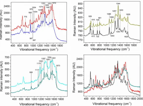
patch. This was done, separately, for the following expected component proxies: horse heart cytochrome c (hhcytc) (Sigma Aldrich, Hamburg, Germany) in Phosphate buffer solution (PBS) (Roth, Karlsruhe, Germany); riboflavin phosphate (Sigma Aldrich, Hamburg, Germany) in PBS; hhcytc in PBS with excess sodium dithionite (Merck, Darmstadt, Germany); hhcytc in PBS with excess potassium hexacyanoferrate (III) (Sigma Aldrich, Hamburg, Germany); ribo-flavin phosphate in PBS with excess sodium dithionite; riboribo-flavin phosphate in PBS with excess potassium hexacyanoferrate; an aqueous solution of sodium alginate (Sigma Aldrich, Ham-burg, Germany); pure PBS; PBS with sodium dithionite; and PBS with potassium hexacyano-ferrate. Sodium dithionite and potassium hexacyanoferrate, respectively, were used to obtain the reduced and oxidized hhcytc and riboflavin phosphate. Riboflavin phosphate, hhcytc and sodium alginate have been used as standard proxies for flavins,cytochromesand polysaccha-rides present in the biofilm, respectively. In the resulting proxy component SECRaM images, each pixel contained only some of all the Raman bands of the analyzed molecule, since in SERS the signal intensity is strongly dependent on the distance from the metallic surface and on molecular orientation, as only modes parallel to surface normal become enhanced [49,53,80]. This is true even for pure compounds if they are non-uniformly oriented, and especially for macromolecules such as hhcytc and alginate. To overcome this problem, we have averaged over all signal-containing pixels in each scan, to obtain the proxy component spectra shown in
Fig 1. The peak at 1086 cm-1in both the riboflavin phosphate and the hhcytc spectra is attrib-uted to phosphate [81–84]. InFig 1ctwo different spectra of sodium alginate appear, averaged on different signal-containing pixels of the same scan, because when averaging these two spec-tra, not all peaks are resolved. As seen inFig 1d, all main expected components have coinciding peaks. Therefore a special approach had to be employed to analyze the SECRaM data in biofilm samples, as detailed below.
SECRaM Data analysis
As seen from the individual component spectra (Fig 1), there are many coinciding or semi-coinciding peaks shared bycytochromes, flavins and polysaccharides. As explained above, in SERS peak intensity greatly depends on the distance from the surface and on the vibrational mode orientation [49,50], rendering data analysis algorithms that depend on peak intensity ratio, such as cluster analysis, not applicable to this type of heterogeneous sample, where the AgNp size and shape is non-uniform, and the components are anisotropically distributed in the sample. We therefore had to develop a different method for differentiating between the four following components analyzed in our sample: oxidized flavins, reduced flavins, polysac-charides and reduced+oxidizedcytochromes. As seen inFig 1a, reduced and oxidized cyto-chromeshave very few peaks that can be resolved in order to differentiate between the two redox states, most notably the reducedcytochromepeak at 775 cm-1, absent from the oxidized spectrum. However, most other reduced and oxidized peaks coincide either with each other or with peaks of other components expected to be found in the biofilm. For example, the oxidized hhcytc peak at 1499 cm-1coincides with a shoulder in the reduced hhcytc spectrum and with a peak in the alginate spectrum. The reduced hhcytc peak at 1432 cm-1coincides with an alginate peak. The oxidized hhcytc peak at 1331 cm-1coincides with both a shoulder in the reduced hhcytc spectrum and the alginate peak at 1337 cm-1as well as its shoulder at 1328 cm-1. And while reduced hhcytc coincides with its oxidized counterpart only at 926 but not at 903 or 914 cm-1, the alginate peak at 909 cm-1interferes with the latter two peaks. Therefore we have treated reduced and oxidizedcytochromestogether.
following approach was employed: Two types of Raman image were first generated from the biofilm SECRaM scan acquired on day 6.Type I, unique peaks:the sum of all sum filters for the peaks of each proxy component, which were removed from any other peaks or shoulders by at least 4 cm-1;Type II, coinciding peaks of two components:the sum of all sum filters for the coinciding peaks of each two proxy components i.e. the ones separated by less than 4 cm-1. These two types of Raman images were then individually binarized by taking the most intense 10% pixels of each image. This thresholding provided optimized chemical maps for all compo-nents, avoiding over-saturation and excessive coincidence of component-specific pixels. Aver-age spectra were calculated from these binarized Raman imAver-ages: one of each type for each analyzed biofilm component. For each of the four analyzed biofilm components (excluding phosphate, see below), the average spectra for unique peaks (Type I) were compared with those for coinciding peaks (Type II). This was performed as follows: (i) The sum of: Type I average spectrum for component A (e.g.cytochromes) + Type I average spectrum for component B (e.g. polysaccharides), was compared to the Type II average spectrum for the coinciding peaks of A and B. (ii) The sum of Type II average spectrum for the coinciding peaks of A and B + Type II average spectrum for the coinciding peaks of B and C (e.g. reduced flavins) was pared to the Type I average spectrum of component B. This was done for all component com-binations. Any peak appearing in the two compared spectra in both (i) and (ii) was assigned to the respective analyzed biofilm component if it also appeared in the pure proxy component spectrum. In this way, seven to nine component-specific peaks were assigned to each analyzed biofilm component. These peaks are clearly marked inFig 1. For a partial peak assignment list,
Fig 1. SERS spectra of expected biofilm component proxies.Each component was dissolved either in water (Sodium Alginate) or in phosphate buffer (hhcytc and riboflavin phosphate) and mixed with colloidal silver for Raman surface enhancement. a) reduced (red) and oxidized (blue) hhcytc; b) reduced (black) and oxidized (olive) riboflavin phosphate; c) two different SERS spectra of sodium alginate; d) spectra of reduced hhcytc, reduced riboflavin phosphate and sodium alginate overlaid, for comparison.
seeS1 Table. For phosphate, the typical peak at 1086 cm-1appearing in the riboflavin phos-phate and the hhcytc spectra was assigned [81–84].
Sum Raman images, consisting of the sum of all sum filters for the final analyzed compo-nent peaks, were produced for each scan. The top 10% most intense pixels in the resulting sum images were selected for the binarized chemical map images. 10% has been chosen, as it pro-vided the clearest images. Lower thresholding has produced over-saturated chemical maps. The binarized images also served for creating an average spectrum for each individual compo-nent in the biofilm. SECRaM images summed over 1400–1600 cm-1were obtained to show the Raman surface enhancement evolution in the biofilm.
Sample fixation and drying for SEM-EDX
For SEM-EDX, samples on glass coverslip support (0.17 mm thick) were used. To both open the sample setup and reduce sample size to fit the SEM-EDX sample holder, a circle of ca. 7 mm diameter was drawn using a diamond scribe (TH.Geyer, Renningen, Germany) around the Ag/AgCl ink patch. Then the glass around the circle was removed and discarded, and the top coverslip was separated from the support coverslip and positioned face up. The biofilm on both the top and support coverslips was immediately fixed with 4% glutaraldehyde in cacocly-date buffer (Electron Microscopy Sciences, PA, USA) and was incubated overnight at 4°C. The next day, the fixing agent was rinsed off with Milli-Q water and subsequently stepwise solvent-exchanged with a graded series of acetone/water solutions (30%, 50%, 80%, 90%, 95%, 100%, each for 20 min). The sample was then critical point dried (Leica EM CPD300) and sputtered with a 15 nm Cr layer (Leica EM SCD500), following the procedure used by Ray et al [85]. Of the three replicates prepared for SEM-EDX analysis, 2 were fixed and analyzed seven days after sealing. One sample analyzed 14 days after sealing originates from an identical experiment pre-pared from the same strain a few months earlier.
Electron-microscopy and Energy-Dispersive X-Ray Spectroscopy (SEM
and EDX)
The morphology and structure of the samples were investigated by scanning electron-micros-copy (SEM). A Zeiss Merlin VP field-emission SEM was used. In order to achieve high surface-sensitivity, the energy of the electron beam was set to 1.5 kV, unless otherwise specified, and the secondary electron (SE) detector was used. Working distance and beam current in imaging mode were approximately 1.5 mm and 14pA, respectively. The spatial resolution for imaging under these conditions was ca. 5 nm.
The SEM is equipped with a Bruker High-speed high-solid-angle XFlash1
mm and 18 pA, respectively. Coinciding SEM and EDX images were superimposed using ImageJ.
To acquire SEM-EDX images of the bare Ag/AgCl patch, it was subjected to the same fixa-tion, solvent exchange, critical point drying and sputtering procedures described above. To compare the SEM-EDX images of the biofilm to those of freshly deposited bacteria, aS. onei-densisculture in minimal medium (OD600= 1.0) diluted to 50% in fresh medium was pipette
deposited on the Ag/AgCl patch. However, the chamber was not sealed. Instead, after two min-utes the patch with the freshly deposited bacteria was subjected to the same fixation, solvent exchange, critical point drying and sputtering procedures described above.
Results and Discussion
Shewanella oneidensis
MR-1 produced AgNp-containing biofilm at an
Ag/AgCl solid interface
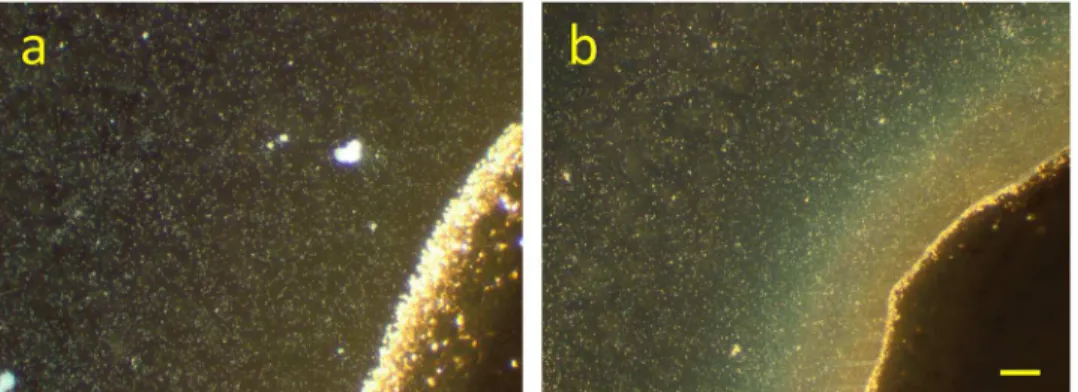
The development ofS.oneidensisMR-1 biofilms at a Ag/AgCl solid interface has been moni-tored in time by digital photography, light microscopy, SEM-EDX and SECRaM. The biofilms have already been visible to the naked eye after three days, and had a brownish hue with a sil-very luster when tilted in the light (S1 Fig). InFig 2, a part of the Ag/AgCl patch is shown, seven days after the setup was closed. In this dark field light microscopy image, the patch is seen as a dark area, while the microbial cells appear as bright dots. The biofilm can be observed as a brownish-orange light refracting substance at the patch. The color can be attributed to one or a combination of the following components, which absorb in the green: AgNp,cytochromes, and polysaccharides. To confirm that the feature seen inFig 2bis indeed the result of bacterial colonization of the Ag/AgCl patch while using it as an electron acceptor, control experiments were performed (S2 Fig). In the abiotic control no such observations were made, and the Ag/ AgCl patch remained unchanged. In the non-reducible ink control, the bacteria did not survive and only their debris could be seen, with no visible changes near the polymer patch.
In the soluble electron acceptor control, performed by adding disodium fumarate to the bac-terial suspension, the bacteria survived and seem to have also precipitated AgNp and agglomer-ated around the Ag/AgCl patch; however, no light-refractive substance was observed (S2 Fig), indicating that a biofilm might not have been formed or was not as rich in polysaccharides. This observation may either indicate differences in biomass production rates due to a different energetic gain for bacterial growth with fumarate and Ag(I) compared to Ag(I) alone as the ter-minal electron acceptor; or that the bacteria might have chosen, while still respiring Ag(I) from the Ag/AgCl patch, not to build structures on it that would constrain fumarate diffusion to the cells. It has been previously shown that different multi-hemecytochromesinShewanellaare responsible for electron transfer to a variety of terminal electron acceptors (TEA), including fumarate, nitrate, Fe(III) and Mn(III/IV) oxides and their complexes, flavins and electrodes ([23,28] and references therein), however they all receive respiratory electrons from one pro-tein, CymA, and many of them are expressed immediately upon the onset of anoxic conditions. This is apparently related to thecrpgene expression [17]. Their function seems to be dependent on the small tetrahemecytochromeand/or fumarate reductase, either of which can mediate electron transfer to all of the abovementioned TEAs [28]. It is therefore clear thatShewanella can use different terminal electron acceptors in parallel, as observed here. Furthermore, it has been shown that diffusion within aShewanellabiofilm is restricted, especially near the surface [86].
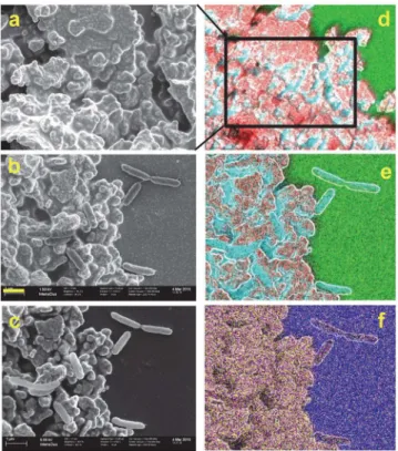
bacteria and on Ag/AgCl patches with freshly deposited and immediately fixedS.oneidensisin minimal medium. In the SEM images we could observe the typical topographies of the bare Ag/AgCl patch and the expected morphology of planktonic cells (Fig 3b and 3c). After imaging by SEM, the elemental composition of the sample was recorded by SEM-EDX (Fig 3d, 3e and 3f). As seen inFig 3, sulfur (S) and phosphorus (P) are abundant in the Ag/AgCl ink polymer matrix, while oxygen (O) and silicon (Si) are abundant in the glass support. Nitrogen could not be significantly detected in these EDX images, and therefore in the following figures carbon (C) is used as a marker for bacterial cells. For EDX peak assignment, seeS3 Fig.
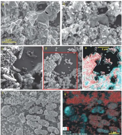
Using SEM-EDX analysis of the samples from days 7 and 14 we could observe the formation of an AgNp-containing biofilm at the Ag/AgCl patch (Fig 4). InFig 4a and 4c, acquired with 1.5 kV electron beam acceleration, the EPS is observed covering the surface and obscuring the typical Ag/AgCl patch topography. This topography is revealed in the image acquired at 18 kV, where the electron beam can penetrate deeper, under the EPS contour (Fig 4b). InFig 4a–4e,
AgNp are seen in their previously documented shapes [87], as also previously reported for other AgNp-precipitating bacterial species, such asPseudomonas stutzeri[88] andMorganella psychrotolerans[89]. In the samples reported here, the most abundant are circular AgNp of 110–190 nm diameter, triangular nanoprisms with a perpendicular bisector of 200–240 nm, and snipped nanoprisms (oblate unequal hexagons) of 250–400 nm. Prism thickness is ca. 20 nm, corresponding to a 1:10 to 1:20 aspect ratio. At this size-range, plasmon resonance for both triangular and snipped nanoprisms would be at>700 nm [90,91]. However, as edges
become rounder, plasmon resonance becomes blue-shifted [87] until reaching a maximum near the excitation wavelength used in our study, 532 nm, as previously observed for semi-round particles of ca 125 nm [92], or as can be expected of larger but rounder particles, as the ones reported here. The way different AgNp shapes and sizes correspond to Raman surface enhancement at different exciting wavelength frequencies has been previously reported [93–
95].
InFig 4c, acquired at 1.5 kV, the outer membranes of the bacteria, as well as the EPS cover-ing the Ag/AgCl patch (right bottom corner) are clearly seen, whereas inFig 4d, the stronger 5 kV electron beam penetrates deeper, revealing the Ag/AgCl patch topography under the EPS, as well as AgNp found under the outer membrane of the bacteria, possibly in the periplasmic space. Triangular Ag nanoprisms are particularly easy to spot under the outer membrane of some bacteria. Similar findings have been reported for other species [88,96]. Some bacteria also touch AgNp externally. However, most of the AgNp precipitate seen inFig 4a–4dis located on
Fig 2. Dark field microscopy (x10) ofS.oneidensisMR-1 at the Ag/AgCl solid interface.Bacteria appear as bright dots, and the Ag/AgCl patch is the dark area at bottom right corner.a)30 min after sealing the setup, b)7 days after sealing the setup: a brownish-orange light refracting substance has accumulated at the Ag/ AgCl patch. Scale bar 50μm.
the EPS, suggesting that most of the SERS signal will likely originate from EPS components. This may also indicate that the bacterial Ag(I) reducing activity, i.e. electron transfer to extra-cellular IEA, is mediated by the EPS and its redox active components, namelycytochromesand flavins. It has been shown before that current production byShewanellaat an anode depends on EPS production [97].
After 14 days, both the EPS and many bacteria become completely covered with spherical AgNp of 60–100 nm diameter as well as rougher aggregates ranging between 140–220 nm, with surfaces featuring smaller spherical particles of 15–40 nm, spaced 4–6 nm (Fig 4f and 4g, andS4 Fig). This type of surface roughness has been shown to create considerable Raman enhancement at 514 nm [98].
AgNp precipitated by
S
.
oneidensis
produce Raman enhancement for
SECRaM
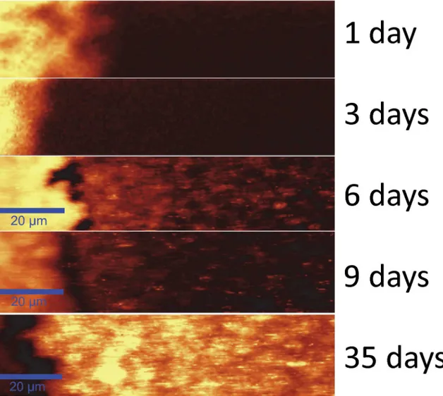
A time series of the development of Raman signal summed over 1400–1600 cm-1in a typical sample is shown inFig 5. The entire data series has been acquired under the same measure-ment conditions. On the left, the Ag/AgCl patch is visible as an area of high intensity due to Raman enhancement by the silver particles found in the Ag/AgCl patch itself. After 9 days the Raman intensity on the patch is decreased, and after five weeks a very poor signal is obtained in this region, possibly due to an excessive accumulation of light refracting molecules, such as flavins and EPS, hindering detection. On days 1 and 3 no Raman signal is detected outside the Ag/AgCl patch. However, on day 6 Raman signal hotspots appear where bio-deposited AgNp
Fig 3. SEM-EDX analysis of a Ag/AgCl patch with (b, c, e, f) and without (a and d) freshly depositedS. oneidensiscells.Left column: SEM images, right column: overlay SEM-EDX images. Color code: Red: Ag, Cyan: C, Green: O, Magenta: P, Yellow: S, Blue: Si. Yellow bar is 1μm and applies to all images but d. Images a and b were obtained at 1.5 kV and c to f at 5 kV, compare withFig 4. kV stands for kilovolts and represents the acceleration voltage of the electron beam.
have reached the adequate size and shape for detecting the surface enhanced Raman signal when using a 532 nm excitation wavelength. The hotspot pattern changes as the biofilm devel-ops, as can be seen on days 6, 9 and 35. Please note that an artifact is seen in the images, where the optical trapping effect exerted by the laser beam results in the dragging of solid or semi-solid objects, such as AgNp or perhaps even entire bacteria [68,99], in the wet biofilm for a few pixels, resulting in the appearance of horizontal lines that can clearly be seen in the SECRaM image.
InFig 6, larger SECRaM images are shown overlaid on bright field optical-microscopy images, where Ag-precipitating bacteria and bacterial aggregates are seen as dark spots (com-pareS1andS2Videos, whereS.oneidensisbacteria are not seen in bright-field microscopy until they precipitate Ag). While on days 6 and 9 the Raman intensity hotspots do not coincide with the locations of such bacteria, on day 35 the most intense Raman signal is localized to bac-terial aggregates. As seen above (Fig 4), this is explained by the observation that in samples fixed on day 7 for SEM-EDX, most AgNp were found on the EPS and not on bacterial outer membranes. In the sample fixed on day 14 the bacteria themselves show dense AgNp precipi-tates on their outer membranes. This also means that the biofilm chemical composition obtained by SECRaM will correspond on days 6 and 9 to the EPS and on day 35 to the vicinity
Fig 4. SEM-EDX images of 7 days (a-e) and 14 days (f-g) old biofilms.Scale bar 2μm applicable for panels a, b and c (see bar at a) d, and e (see bar at e). For panels f and g scale bar is 3μm (see bar at g). Panels a, c and f were acquired at 1.5 kV; d, e and g at 5 kV and b at 18 kV. In EDX images red is silver (Ag) and cyan is carbon (C). Image e is a superposition of the EDX color maps for Ag and C and a contour image produced from panel d using ImageJ plugin FeatureJ Edges. From panels a-e it is evident that AgNp in various shapes and sizes can be found both on the EPS and under the outer membrane of some bacteria (see text for more details). In panels f and g both the EPS and the outer membrane of some bacteria are completely covered with roughly spherical AgNp or agglomerations thereof. For a higher resolution segment of image f, seeS4 Fig.
Fig 5. SECRaM time series of theS.oneidensisbiofilm at the Ag/AgCl patch (patch seen on the left): 1, 3, 6, 9 and 35 days after sealing the setup. The Raman signal is summed over 1400–1600 cm-1. The 20μm scale bar applies to all images. Intensity scale bar on left. All images normalized to 1000 a. u., without background subtraction. With time, Raman intensity hotspots develop where Raman-active biofilm components directly touch bio-produced AgNp. Raman hotspot intensity and distribution change with biofilm development, for discussion see text andFig 6.
doi:10.1371/journal.pone.0145871.g005
Fig 6. Time series of theS.oneidensisbiofilm at the Ag/AgCl patch—surface enhanced Raman signal
overlaid on light microscopy.6, 9 and 35 days after sealing the setup. Ag/AgCl patch seen as dark area on the left. Grayscale: light microscopy, bright field, 20×. Black features are bacteria or bacterial aggregates, which have already precipitated Ag. Before precipitating Ag the bacteria are not visible in bright field, see also S1–S4videos. Overlay: SECRaM image summed over 1400–1600 cm-1, intensity scale bar on left, all images normalized to 1000 a.u., without background subtraction. Yellow scale bar: 20μm.
of bacterial aggregates. However, since SERS signal is limited to ca. 2 nm from the AgNp sur-face [49,50], it is difficult to say whether the signal on day 35 stems from the bacterial outer membranes or from external components touching the precipitated AgNp.
All through the time series, more Raman intensity is detected near the Ag/AgCl patch, apparently because the probability of AgNp precipitation outside the patch depends on Ag(I) diffusion from AgCl particles in the patch to the rest of the biofilm. Since AgCl is very poorly soluble in water (Molar solubility 1.33×10⁻⁵M [100]), it is also possible that flavins assist in its dissolution by chelation, as they do in the case of insoluble iron oxides [37,38]. Either way, since Ag(I) is being constantly consumed by bacterial respiration, the dissolution reaction for AgCl never reaches equilibrium, and Ag(I) is continuously released into the aqueous phase.
Chemical mapping of MR-1 biofilm using SECRaM
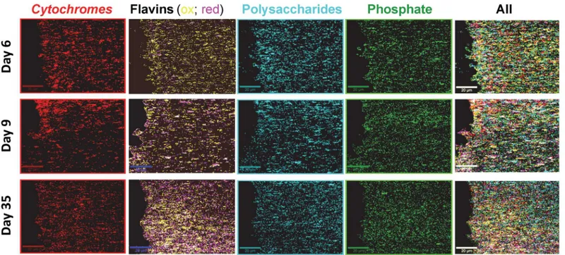
After baseline subtraction of the SECRaM images and assignment of the different components (seeMaterials and Methods), intensity maps for each component have been obtained. For visu-alization and spectral averaging, the most intense 10% pixels in each intensity map have been chosen, and are shown inFig 7as single and superimposed component distribution maps. An in-situtime evolution of biofilm chemical composition has been obtained. Please note that pix-els not belonging to the most intense 10% have been omitted, so that component coincidence is in reality more extensive than shown. Spectra averaged over the 10% most intense pixels for each component (i.e. the pixels seen in color inFig 7) are shown inS5 Fig, overlaid with the spectrum of each pure proxy component (seen also inFig 1). In the averaged biofilm spectra, peaks stemming from the pure components appear alongside peaks originating from other bio-film components coinciding within the same pixel.
Distribution profiles for the different components in the sample are seen inFig 8. On day 6, all components but phosphate are detected more intensely closer to the Ag/AgCl interface. On day 9, onlycytochromesare detected more abundantly at the Ag/AgCl interface. On day 35, only flavins andcytochromesare detected more abundantly at the Ag/AgCl interface. Cyto-chromesand flavins follow the SERS hotspot distribution the most closely of all four compo-nents. Forcytochromes, this is probably caused by a resonance of the Q-band region (green light absorption) with the excitation wavelength, which, multiplied with the surface enhance-ment for both the incident and the scattered light, results in a disproportionately higher enhancement of its signal [61,80]. Flavins, which absorb at ca. 370 nm and 450 nm [101], are not in resonance with the excitation wavelength used here, and the larger dependence of their detection on the SERS hotspot distribution, compared to phosphate and polysaccharides, may indicate that they tend to attach to AgNp in a favorable distance and/or orientation for detec-tion using SERS. This observadetec-tion is also supported by the excepdetec-tionally good S/N obtained for pure riboflavin phosphate mixed with colloidal silver (Fig 1). Flavins andcytochromesare therefore more abundantly detected near the Ag/AgCl solid interface, however this does not necessarily indicate that they are actually present there in higher concentrations. On day 35 fla-vins are detected more intensely thancytochromes, possibly indicating an accumulation of fla-vins in the biofilm.Cytochromes, being proteins, depend on a living cell to produce them and prevent them from denaturing, and therefore their concentration in the biofilm is limited by the number of living cells supported by the biofilm. Flavins, on the other hand, being much smaller and therefore more stable molecules, once discharged by the living bacterium can out-live it and be accumulated in the biofilm. Another possible explanation is that with time the fla-vins accumulate preferentially at the AgNp, thus preventing the enhancement of the
8). In contrast, polysaccharides have been first detected more abundantly next to the Ag/AgCl patch, then spread across the image to the right, and eventually their last distribution peak has moved out of the chemical map frame, possibly indicating a continued growth of the biofilm, with further accumulation of EPS in that direction. The oscillations visible inFig 8, especially in the profile of thecytochromes, is an indication of the dynamical spatial organization of the biomass [103,104]. For day 6 the well resolved peaks point to a spatial clustering of the cells and EPS. As time advances, the biofilm population grows, first in proximity of the Ag/AgCl patch as can be seen from the enhancedcytochromesignal on day 9, and then the population becomes more homogeneous by day 35. Similar results have been observed in previously ana-lyzed samples, produced in identical experiments prepared from the same strain at another date (an example is shown inS6 Fig).
As explained in the Materials and Methods section, it has not been possible to resolve reduced from oxidizedcytochromeswith the method used here. Thus, they were treated as one single component. However, since theν15pyrol breathing peak at 775 cm-1, typical of reduced cytochromes[72,105], is missing from the biofilmcytochromeaveraged spectrum (S5 Fig,
Fig 7. Chemical maps of a typical AgNp-precipitatingS.oneidensisbiofilm, produced by SECRaM.Top row: 6 days, middle row: 9 days, bottom row: 35 days after sealing the setup. Mapped biofilm components: Red:cytochromes, yellow: oxidized flavins, magenta: reduced flavins (white: reduced and oxidized flavins coinciding), cyan: polysaccharides, green: phosphate. Extreme right column is a superposition of all components. Scale bar: 20μm.
doi:10.1371/journal.pone.0145871.g007
Fig 8. Component profiles, extracted using ImageJ from the chemical maps inFig 7and smoothed using Origin.Teal: polysaccharides; Maroon:cytochromes; Black: reduced flavins; Olive: oxidized flavins; Green: phosphates; Grey: SERS hotspots, normalized to fit the scale of the other components.
maroon), one may deduce that most of the Raman signal arising fromcytochromesis accounted for by oxidizedcytochromes. This is true for days 6, 9 and 35, and it may indicate that the cyto-chromesthroughout the biofilm were maintained oxidized for the duration of the measure-ments by electron transfer to Ag(I). However, the dominance of the averaged spectra by oxidized, rather than reduced,cytochromesmay also have two other explanations: (i) It may reflect the sensitivity of the UV/vis absorption spectrum ofcytochrometo external conditions, such as pH, ionic strength and surface tension, especially in the vicinity of the excitation wave-length used here [106]. 532 nm is a wavelength on thecytochromeUV/Vis spectrum that is par-ticularly sensitive to such conditions, meaning that under the as yet unknown
microenvironmental conditions prevailing in the biofilm at different biofilm development stages and distances from the solid interface, oxidizedcytochromesmay be at a stronger reso-nance with the exciting wavelength than reducedcytochromes, resulting in a disproportionate enhancement of the oxidizedcytochromesignal in our measurements, which may not indicate a higher concentration; (ii) Another possibility is that detection ofν15pyrol breathing mode at 775 cm-1, belonging to the B1gsymmetry group, which is thus preferentially enhanced when
the heme plane is oriented perpendicular to the AgNp surface [52,80], is suppressed under the experimental conditions described here, due to a possible preferential heme-parallel orienta-tion of AgNp precipitated in the vicinity ofcytochromes. Such preferential orientation may be deduced, for example, from recent X-ray diffraction data of undecahemecytochrome crystal-ized in the presence of soluble Fe(III) chelates [23,26].
For flavins it is easier to discern reduced from oxidized, based on vibrational frequencies (Fig 1), enabling us to report the distribution of reduced vs. oxidized flavins in space and time (Fig 6). As seen, on day 6 more oxidized flavins were detected, but with time reduced flavins became more abundant, possibly indicating an increasing difficulty of the bacteria to find an adequate electron acceptor. This may arise from an increase in biofilm density next to the solid interface with time [86,107], brought about by the accumulation of cells, cell debris and EPS during the experiment. Such an accumulation of biofilm components at the Ag/AgCl patch may inhibit either or both flavin diffusion towards the poorly soluble Ag(I) salt, or Ag(I) diffu-sion away from the original patch to other parts of the biofilm. In both cases, this would result in less flavin (re)oxidation and an accumulation of reduced flavins.
Conclusion and Outlook
environments [109] and photographic waste [110], precipitation of AuNp from Au(III) con-taminated water byPseudomonas aeruginosabiofilms [111], removal of various metal species from waste electronic scrap leachate byDesulfovibrio desulfuricans[112], and production of AgNp byAspergillus flavus[113],Morganella sp. [89,114],Lactobacillus[96], various cyano-bacteria [115] andPseudomonas stutzeri[88]. The method presented here will open new ways of analysis by chemical mapping over time in 3D andin situ, without disturbing the involved microorganisms, for a wide range of applications.
Supporting Information
S1 Fig. Digital images of S. oneidensis MR-1 biofilm at the cured Ag/AgCl ink patch.
Images recorded using an LG G3 mobile phone back digital camera. Left: the experimental setup consisting of a cured Ag/AgCl ink patch on a standard microscope slide, whereS.oneidensis bac-teria in defined medium were deposited and then covered with a standard cover slip. Silicone vacuum grease is used as both spacer and sealant to keep the setup air-tight. Middle and right columns: biofilm development as seen by the naked eye. On day 1 the Ag/AgCl patch is light beige in color. With time, it becomes darker, and a brownish biofilm visibly grows around it. When tilted in the light, the brownish biofilm exhibits a silvery luster, indicating the precipitation of Ag particles inside it. Sample was photographed 1, 3, 6, and 35 days after sealing the setup. (PDF)
S2 Fig. Dark field microscopy images (x10) of control experiments.Top: Abiotic control, performed in the absence of bacteria (setup contains Ag/AgCl patch and minimal medium, but no bacteria). No changes to the Ag/AgCl patch observed (compareFig 1). Middle: non-reduc-ible ink control with dielectric polymer instead of Ag/AgCl ink (setup contains cured dielectric polymer patch andS.oneidensisin minimal medium, without Ag/AgCl or any supplementary electron acceptors). The bacteria did not survive and did not settle at the dielectric polymer. Bottom: Soluble electron acceptor control, where 20 mM fumarate were added to the original setup. The bacteria survived and aggregated around the Ag/AgCl patch, but no brownish light-refracting material was deposited (compareFig 1).
(PDF)
S3 Fig. EDX peak assignment, performed by the Bruker Esprit software supplied with the Bruker Quantax detector, based on its spectral library.Left: averaged over a 2x2 (μm)2 area
of original Ag/AgCl patch covered with EPS such as seen on the right bottom ofFig 3c–3e.
Right: averaged over a 0.8x0.8 (μm)2 area of a Shewanella bacterium lying directly on the glass
support. Both acquired on a sample fixed 7 days after sealing the setup. (PDF)
S4 Fig. Higher resolution image of a detail fromFig 3f.
(PDF)
S6 Fig. Figures analogous to Figs6,7and8, for a replicate experiment.Bacteria of the same strain, prepared and analyzed at another point in time, in the same way described in the article. The results are very similar to the ones discussed in the text.
(PDF)
S1 Table. Raman peak assignment.Unassigned peaks were detected in pure component anal-ysis (seeFig 1) but lack assignment in literature. If reduced (red) and oxidized (ox) species can be differentiated, it is mentioned in the table. For molecular schemes, please see references. (PDF)
S1 Video. Bright field (20×) videos of the system, 1 day after sealing.The bacteria are not visible in bright field microscopy.
(AVI)
S2 Video. Bright field (20×) videos of the system, 6 days after sealing.When the bacteria started to precipitate AgNp they became visible in bright field microscopy. Twitching activity is seen.
(AVI)
S3 Video. Bright field (20×) videos of the system, 9 days after sealing.When the bacteria started to precipitate AgNp they became visible in bright field microscopy. Twitching activity is seen.
(AVI)
S4 Video. Bright field (20×) videos of the system, 35 days after sealing.With time, the bacte-ria organize in aggregates.
(AVI)
Acknowledgments
The authors are grateful for using the analytical facilities of the Centre for Chemical Micros-copy (ProVIS). They thank Hans H. Richnow for providing the analytical capacity of ProVIS and for helpful comments. The authors would like to thank the Geomicrobiology Group, led by Prof. Dr. Andreas Kappler at the Zentrum für Angewandte Geowissenschaften in Universi-taet Tuebingen for generously supplying them with anS.oneidensisculture. They would also like to add special thanks to Dr. Lorenz Adrian, Dr. Hryhoriy Stryhanyuk, Dr. Thore Rohwer-der, Ute Kuhlicke, Cornelia Dilßner, Monika Neytschev, Franciska Hedrich and Anne Kuchen-buch at the Helmholtz Centre for Environmental Research (UFZ) for procurement, training and technical support.
Author Contributions
Conceived and designed the experiments: GS. Performed the experiments: GS MS. Analyzed the data: GS MS MGM FH NM. Contributed reagents/materials/analysis tools: GS FH MGM NM. Wrote the paper: GS MS FH MGM NM.
References
1. Logan BE. Exoelectrogenic bacteria that power microbial fuel cells. Nat Rev Microbiol. 2009; 7 (5):375–81. doi:10.1038/nrmicro2113PMID:19330018
3. Lovley DR. Microbial fuel cells: novel microbial physiologies and engineering approaches. Curr Opin Biotechnol. 2006; 17(3):327–32. PMID:16679010
4. Holmes DE, Bond DR, Lovley DR. Electron Transfer by Desulfobulbus propionicus to Fe (III) and Graphite Electrodes. Appl Environ Microbiol. 2004; 70(2):1234. PMID:14766612
5. Lovley DR. Dissimilatory Fe (III) and Mn (IV) Reduction. 1991; 55(2):259–87.
6. Nealson KH, Belz A, McKee B. Breathing metals as a way of life: Geobiology in action. Antonie van Leeuwenhoek, Int J Gen Mol Microbiol. 2002; 81(1–4):215–22.
7. Nealson KH, Saffarini D. Iron and manganese in anaerobic respiration: environmental significance, physiology, and regulation. Annu Rev Microbiol. 1994; 48:311–43. PMID:7826009
8. Melton ED, Swanner ED, Behrens S, Schmidt C. The interplay of microbially mediated and abiotic reactions in the biogeochemical Fe cycle. Nat Rev Microbiol. 2014; 12(12):797–809. doi:10.1038/ nrmicro3347PMID:25329406
9. Klüpfel L, Piepenbrock A, Kappler A, Sander M. Humic substances as fully regenerable electron acceptors in recurrently anoxic environments. Nat Geosci. 2014; 7(February):195–200. 10. Roden EE, Kappler A, Bauer I, Jiang J, Paul A, Stoesser R, et al. Extracellular electron transfer
through microbial reduction of solid-phase humic substances. Nat Geosci. 2010; 3(6):417–21. 11. Salas EC, Berelson WM, Hammond DE, Kampf AR, Nealson KH. The impact of bacterial strain on the
products of dissimilatory iron reduction. Geochim Cosmochim Acta. 2010; 74(2):574–83. PMID: 20161499
12. Marshall MJ, Beliaev AS, Dohnalkova AC, Kennedy DW, Shi L et al. c-Type Cytochrome-Dependent Formation of U(IV) Nanoparticles by Shewanella oneidensis. PLoS Biol. 2006; 4(8):e268.
13. Rosenbaum MA, Franks AE. Microbial catalysis in bioelectrochemical technologies: Status quo, chal-lenges and perspectives. Appl Microbiol Biotechnol. 2014; 98(2):509–18. doi: 10.1007/s00253-013-5396-6PMID:24270896
14. Bretschger O, Cheung ACM, Mansfeld F, Nealson KH. Comparative microbial fuel cell evaluations of Shewanella spp. Electroanalysis. 2010; 22(7–8):883–94.
15. Logan BE, Rabaey K. Conversion of Wastes into Bioelectricity and Chemicals by Using Microbial Electrochemical Technologies. Science. 2012; 337(6095):686–90. doi:10.1126/science.1217412 PMID:22879507
16. Schröder U, Harnisch F, Angenent LT. Microbial electrochemistry and technology: terminology and classification. Energy Environ Sci. 2015; 8(2):513–9.
17. Gao H, Wang X, Yang ZK, Chen J, Liang Y, Chen H, et al. Physiological roles of ArcA, Crp, and EtrA and their interactive control on aerobic and anaerobic respiration in Shewanella oneidensis. PLoS One. 2010; 5(12).
18. El-Naggar MY, Wanger G, Leung KM, Yuzvinsky TD, Southam G, Yang J, et al. Electrical transport along bacterial nanowires from Shewanella oneidensis MR-1. Proc Natl Acad Sci. 2010; 107 (42):18127–31. doi:10.1073/pnas.1004880107PMID:20937892
19. Leung KM, Wanger G, Guo Q, Gorby Y, Southam G, Lau WM, et al. Bacterial nanowires: conductive as silicon, soft as polymer. Soft Matter. 2011; 7(14):6617.
20. Gorby Y a, Yanina S, McLean JS, Rosso KM, Moyles D, Dohnalkova A, et al. Electrically conductive bacterial nanowires produced by Shewanella oneidensis strain MR-1 and other microorganisms. Proc Natl Acad Sci. 2006; 103(30):11358–63. PMID:16849424
21. Pirbadian S, Barchinger SE, Leung KM, Byun HS, Jangir Y, Bouhenni RA, et al. Shewanella oneiden-sis MR-1 nanowires are outer membrane and periplasmic extensions of the extracellular electron transport components. Proc Natl Acad Sci. 2014; 111(35):1–6.
22. Strycharz-Glaven SM, Snider RM, Guiseppi-Elie A, Tender LM. On the electrical conductivity of micro-bial nanowires and biofilms. Energy Environ Sci. 2011; 4(11):4366.
23. Breuer M, Rosso KM, Blumberger J, Butt JN. Multi-haem cytochromes in Shewanella oneidensis MR-1: structures, functions and opportunities. J. R. Soc. Interface 2015; 12: 20141117. doi:10.1098/rsif. 2014.1117PMID:25411412
24. Bewley KD, Ellis KE, Firer-Sherwood M a, Elliott SJ. Multi-heme proteins: nature’s electronic multi-purpose tool. Biochim Biophys Acta; 2013; 1827(8–9):938–48. doi:10.1016/j.bbabio.2013.03.010 PMID:23558243
25. Coursolle D, Baron DB, Bond DR, Gralnick JA. The Mtr respiratory pathway is essential for reducing flavins and electrodes in Shewanella oneidensis. J Bacteriol. 2010; 192(2):467–74. doi:10.1128/JB. 00925-09PMID:19897659
for soluble iron chelates. Structure. 2012; 20(7):1275–84. doi:10.1016/j.str.2012.04.016PMID: 22682743
27. Bretschger O, Obraztsova A, Sturm C, Chang IS, Gorby Y, Reed SB, et al. Current production and metal oxide reduction by Shewanella oneidensis MR-1 wild type and mutants. Appl Environ Microbiol. 2007; 73(21):7003–12. PMID:17644630
28. Sturm G, Richter K, Doetsch A, Heide H, Louro RO, Gescher J. A dynamic periplasmic electron trans-fer network enables respiratory flexibility beyond a thermodynamic regulatory regime. ISME J. 2015;1–10
29. Kalathil S, Hashimoto K, Okamoto A. Effect of Ionic Strength on the Rate of Extracellular Electron Transport in Shewanella oneidensis MR-1 through Bound-Flavin Semiquinones. ChemElectroChem. 2014; 1(11):1840–3.
30. Marsili E, Baron DB, Shikhare ID, Coursolle D, Gralnick JA, Bond DR. Shewanella secretes flavins that mediate extracellular electron transfer. Proc Natl Acad Sci. 2008; 105(10):3968–73. doi:10.1073/ pnas.0710525105PMID:18316736
31. Kotloski NJ, Gralnick JA. Flavin electron shuttles dominate extracellular electron transfer by Shewa-nella oneidensis. MBio. 2013; 4(1).
32. Okamoto A, Hashimoto K, Nealson KH, Nakamura R. Rate enhancement of bacterial extracellular electron transport involves bound flavin semiquinones. Proc Natl Acad Sci. 2013; 110(19):7856–61. doi:10.1073/pnas.1220823110PMID:23576738
33. Paquete CM, Fonseca BM, Cruz DR, Pereira TM, Pacheco I, Soares CM, et al. Exploring the molecu-lar mechanisms of electron shuttling across the microbe/metal space. Front Microbiol. 2014; 5 (JUN):1–12.
34. Edwards MJ, White GF, Norman M, Tome-Fernandez A, Ainsworth E, Shi L, et al. Redox Linked Fla-vin Sites in Extracellular Decaheme Proteins Involved in Microbe-Mineral Electron Transfer. Sci Rep. 2015; 5(July):11677.
35. MacHeroux P, Kappes B, Ealick SE. Flavogenomics—A genomic and structural view of flavin-depen-dent proteins. FEBS J. 2011; 278(15):2625–34. doi:10.1111/j.1742-4658.2011.08202.xPMID: 21635694
36. Dym O, Eisenberg D. Sequence-structure analysis of FAD-containing proteins. Prot Sci. 2001; 10:1712–28.
37. Jones ME, Fennessey CM, DiChristina TJ, Taillefert M. Shewanella oneidensis MR-1 mutants selected for their inability to produce soluble organic-Fe(III) complexes are unable to respire Fe(III) as anaerobic electron acceptor. Environ Microbiol. 2010; 12(4):938–50. doi:10.1111/j.1462-2920.2009. 02137.xPMID:20089045
38. Taillefert M, Beckler JS, Carey E, Burns JL, Fennessey CM, DiChristina TJ. Shewanella putrefaciens produces an Fe(III)-solubilizing organic ligand during anaerobic respiration on insoluble Fe(III) oxides. J Inorg Biochem. 2007; 101(11–12):1760–7. PMID:17765315
39. Li R, Tiedje JM, Chiu C, Worden RM. Soluble electron shuttles can mediate energy taxis toward insol-uble electron acceptors. Environ Sci Technol. 2012; 46(5):2813–20. doi:10.1021/es204302wPMID: 22324484
40. Cao B, Shi L, Brown RN, Xiong Y, Fredrickson JK, Romine MF, et al. Extracellular polymeric sub-stances from Shewanella sp. HRCR-1 biofilms: Characterization by infrared spectroscopy and proteo-mics. Environ Microbiol. 2011; 13(4):1018–31. doi:10.1111/j.1462-2920.2010.02407.xPMID: 21251176
41. Knirel YA. O-Specific Polysaccharides of Gram-Negative Bacteria. First edit. Microbial Glycobiology. Elsevier Inc.; 2010. 57–73 p.
42. Ivleva NP, Wagner M, Szkola A, Horn H, Niessner R, Haisch C. Label-free in situ SERS imaging of biofilms. J Phys Chem B. 2010; 114(31):10184–94. doi:10.1021/jp102466cPMID:20684642 43. Cescutti P. Exopolysaccharides. First edit. Microbial Glycobiology. Elsevier Inc.; 2010. 93–108 p. 44. Zhang Y, Ng CK, Cohen Y, Cao B. Cell growth and protein expression of Shewanella oneidensis in
biofilms and hydrogel-entrapped cultures. Mol Biosyst. 2014; 10(5):1035–42. doi:10.1039/ c3mb70520jPMID:24626808
45. Neu TR, Lawrence JR. Biological relevance of microBial glycosylated Extracellular polymeric sub-stances in microbial biofilms. First edit. Microbial Glycobiology. Elsevier Inc.; 733–758 p.
46. Jarvis RM, Law N, Shadi IT, O’Brien P, Lloyd JR, Goodacre R. Surface-enhanced raman scattering from intracellular and extracellular bacterial locations. Anal Chem. 2008; 80(17):6741–6. doi:10. 1021/ac800838vPMID:18661956
gram-negative and gram-positive bacteria. Environ Sci Technol. 2010; 44(13):5210–5. doi:10.1021/ es903684rPMID:20509652
48. Wang H, Law N, Pearson G, Van Dongen BE, Jarvis RM, Goodacre R, et al. Impact of silver(I) on the metabolism of Shewanella oneidensis. J Bacteriol. 2010; 192(4):1143–50. doi:10.1128/JB.01277-09 PMID:20008067
49. Siebert F, Hildebrandt P. Theory of Infrared Absorption and Raman Spectroscopy. In: Vibrational Spectroscopy in Life Science. Wiley-VCH Verlag GmbH & Co. KGaA; 2008. p. 11–61.
50. Haynes CL, Mcfarland AD, Van Duyne RP. Surface-enhanced Raman spectroscopy. Anal Chem. 2005; 77(17):338–A–346–A.
51. Murgida DH, Hildebrandt P. The heterogeneous electron transfer of cytochrome c adsorbed on Ag electrodes coated withω-carboxyl alkanethiols. A surface enhanced resonance Raman spectro-scopic study. J Mol Struct. 2001; 565–566:97–100.
52. Khoa Ly H, Wisitruangsakul N, Sezer M, Feng J-J, Kranich A, Weidinger IM, et al. Electric-field effects on the interfacial electron transfer and protein dynamics of cytochrome c. J Electroanal Chem; 2011; 660(2):367–76.
53. Alvarez-Paggi D, Meister W, Kuhlmann U, Weidinger I, Tenger K, Hildebrandt P, et al. Disentangling Electron Tunneling and Protein Dynamics of 2 Cytochrome c through a Rationally Designed Surface Mutation 1. J Phys Chem B. 2013; 117(20):6061–8. doi:10.1021/jp400832mPMID:23611698 54. Kurouskia D, Postiglionea T, Deckert-Gaudigb T, Deckert V, Ledneva IK. Amide I vibrational mode
suppression in surface (SERS) and tip (TERS) enhanced Raman spectra of protein specimens. Ana-lyst. 2013; 138(6):1665. doi:10.1039/c2an36478fPMID:23330149
55. Kazanci M, Schulte JP, Douglas C, Fratzl P, Pink D, Smith-Palmer T. Tuning the surface-enhanced raman scattering effect to different molecular groups by switching the silver colloid solution pH. Appl Spectrosc. 2009; 63(2):214–23. doi:10.1366/000370209787391987PMID:19215652
56. Biju V, Pan D, Gorby YA, Fredrickson J, McLean J, Saffarini D, et al. Combined spectroscopic and topographic characterization of nanoscale domains and their distributions of a redox protein on bacte-rial cell surfaces. Langmuir. 2007; 23(3):1333–8. PMID:17241055
57. Zeiri L, Bronk BV, Shabtai Y, Eichler J, Efrim SA. Surface-Enhanced Raman Spectroscopy as a Tool for Probing Speci c Biochemical Components in Bacteria. 2004; 58(1):33–40.
58. Preciado-Flores S, Wheeler DA, Tran TM, Tanaka Z, Jiang C, Barboza-Flores M, et al. SERS spec-troscopy and SERS imaging of Shewanella oneidensis using silver nanoparticles and nanowires. Chem Commun. 2011; 47(14):4129–31.
59. Jarvis RM, Goodacre R. Characterisation and identification of bacteria using SERS. Chem Soc Rev. 2008; 37(5):931–6. doi:10.1039/b705973fPMID:18443678
60. Efrima S, Zeiri L. Understanding SERS of bacteria. J Raman Spectrosc. 2009; 40(3):277–88. 61. Millo D, Harnisch F, Patil SA, Ly HK, Schröder U, Hildebrandt P. In situ spectroelectrochemical
investi-gation of electrocatalytic microbial biofilms by surface-enhanced resonance raman spectroscopy. Angew Chemie—Int Ed. 2011; 50(11):2625–7.
62. Ly HK, Harnisch F, Hong S-F, Schröder U, Hildebrandt P, Millo D. Unraveling the interfacial electron transfer dynamics of electroactive microbial biofilms using surface-enhanced Raman spectroscopy. ChemSusChem. 2013; 6(3):487–92. doi:10.1002/cssc.201200626PMID:23371822
63. Smith-Palmer T, Douglas C, Fredericks P. Rationalizing the SER spectra of bacteria. Vib Spectrosc. 2010; 53(1):103–6.
64. Neu TR, Lawrence JR. Innovative techniques, sensors, and approaches for imaging biofilms at differ-ent scales. Trends Microbiol. 2015; 23(4):233–42. doi:10.1016/j.tim.2014.12.010PMID:25623967 65. Neu T, Lawrence J. Advanced Techniques for In Situ Analysis of the Biofilm Matrix (Structure,
Compo-sition, Dynamics) by Means of Laser Scanning Microscopy. In: Donelli G, editor. Microbial Biofilms SE
—4. Springer New York; 2014. p. 43–64.
66. Shotton DM. Confocal scanning optical microscopy and its applications for biological specimens. J Cell Sci. 1989; 94(2):175–206.
67. Halbhuber KJ, König K. Modern laser scanning microscopy in biology, biotechnology and medicine. Ann Anat. 2003; 185(1):1–20. PMID:12597123
68. Pätzold R, Keuntje M, Theophile K, Müller J, Mielcarek E, Ngezahayo A, et al. In situ mapping of nitrifi-ers and anammox bacteria in microbial aggregates by means of confocal resonance Raman micros-copy. J Microbiol Methods. 2008; 72(3):241–8. doi:10.1016/j.mimet.2007.12.003PMID:18255179 69. Sandt C, Smith-Palmer T, Comeau J, Pink D. Quantification of water and biomass in small colony
70. Kniggendorf AK, Meinhardt-Wollweber M. Of microparticles and bacteria identification—(resonance) Raman micro-spectroscopy as a tool for biofilm analysis. Water Res [Internet]. Elsevier Ltd; 2011; 45 (15):4571–82.
71. Virdis B, Harnisch F, Batstone DJ, Rabaey K, Donose BC. Non-invasive characterization of electro-chemically active microbial biofilms using confocal Raman microscopy. Energy Environ Sci. 2012; 5 (5):7017.
72. Virdis B, Millo D, Donose BC, Batstone DJ. Real-time measurements of the redox states of c-type cytochromes in electroactive biofilms: A confocal resonance raman microscopy study. PLoS One. 2014;9(2).
73. Lebedev N, Strycharz-Glaven SM, Tender LM. Spatially resolved confocal resonant Raman micro-scopic analysis of anode-grown Geobacter sulfurreducens biofilms. ChemPhysChem. 2014; 15 (2):320–7. doi:10.1002/cphc.201300984PMID:24402861
74. Haider S, Wagner M, Schmid MC, Sixt BS, Christian JG, Häcker G, et al. Raman microspectroscopy reveals long-term extracellular activity of chlamydiae. Mol Microbiol. 2010; 77(3):687–700. doi:10. 1111/j.1365-2958.2010.07241.xPMID:20545842
75. Pemberton RM, Rawson FJ, Xu J, Pittson R, Drago GA, Griffiths J, et al. Application of screen-printed microband biosensors incorporated with cells to monitor metabolic effects of potential environmental toxins. Microchim Acta. 2010; 170(3):321–30.
76. Lanni EJ, Masyuko RN, Driscoll CM, Aerts JT, Shrout JD, Bohn PW, et al. MALDI-guided SIMS: multi-scale imaging of metabolites in bacterial biofilms. Anal Chem. 2014; 86(18):9139–45. doi:10.1021/ ac5020222PMID:25133532
77. Lanekoff I, Burnum-Johnson K, Thomas M, Cha J, Dey SK, Yang P, et al. Three-dimensional imaging of lipids and metabolites in tissues by nanospray desorption electrospray ionization mass spectrome-try. Anal Bioanal Chem. 2015; 407(8):2063–71. doi:10.1007/s00216-014-8174-0PMID:25395201 78. Hua X, Yu X-Y, Wang Z, Yang L, Liu B, Zhu Z, et al. In situ molecular imaging of a hydrated biofilm in a
microfluidic reactor by ToF-SIMS. Analyst. 2014; 139(7):1609–13. doi:10.1039/c3an02262ePMID: 24571001
79. Melzer S, Winter G, Jäger K, Hübschmann T, Hause G, Syrowatka F, et al. Cytometric patterns reveal growth states of S hewanella putrefaciens. Microb Biotechnol. 2014; 8: 379–391 doi: 10.1111/1751-7915.12154PMID:25185955
80. Kranich A, Ly HK, Hildebrandt P, Murgida DH. Direct Observation of the Gating Step in Protein Elec-tron Transfer: Electric-Field-Controlled Protein Dynamics. J Am Chem Soc. 2008; 130:9844–8. doi: 10.1021/ja8016895PMID:18593159
81. Xu L-J, Lei Z-C, Li J, Zong C, Yang CJ, Ren B. Label-Free Surface-Enhanced Raman Spectroscopy Detection of DNA with Single-Base Sensitivity. J Am Chem Soc. 2015; 137:5149−5154. doi:10.1021/ jacs.5b01426PMID:25835155
82. Greaves SJ, Griffith WP. Surface-Enhanced Raman Scattering (SERS) from Silver Colloids of Vana-date, Phosphate and Arsenate. J Raman Spectrosc. 1988; 19(December 1987):503–7.
83. Pagba CV, Lane SM, Wachsmann-Hogiu S. Raman and surface-enhanced Raman spectroscopic studies of the 15-mer DNA thrombin-binding aptamer. J Raman Spectrosc. 2010; 41(3):241–7. 84. Guerrini L, KrpetićŽ, van Lierop D, Alvarez-Puebla RA, Graham D. Direct Surface-Enhanced Raman
Scattering Analysis of DNA Duplexes. Angew Chemie Int Ed. 2015; 54(4):1144–8.
85. Ray R, Lizewski S, Fitzgerald LA, Little B, Ringeisen BR. Methods for imaging Shewanella oneidensis MR-1 nanofilaments. J Microbiol Methods. 2010; 82(2):187–91. doi:10.1016/j.mimet.2010.05.011 PMID:20561956
86. Renslow R, Babauta J, Majors P, Beyenal H. Diffusion in biofilms respiring on electrodes. Energy Environ Sci. 2013; 6(2):595–607. PMID:23420623
87. Rycenga M, Cobley CM, Zeng J, Li W, Moran CH. Controlling the Synthesis and Assembly of Silver Nanostructures for Plasmonic Applications. Chem Rev. 2012; 111(6):3669–712.
88. Klaus T, Joerger R, Olsson E. Silver-based crystalline nanoparticles, microbially fabricated. Proc Natl Acad Sci. 1999; 96(24):13611–4. PMID:10570120
89. Ramanathan R, O’Mullane AP, Parikh RY, Smooker PM, Bhargava SK, Bansal V. Bacterial kinetics-controlled shape-directed biosynthesis of silver nanoplates using morganella psychrotolerans. Lang-muir. 2011; 27(2):714–9. doi:10.1021/la1036162PMID:21142094
90. Jin R, Cao YC, Hao E, Métraux GS, Schatz GC, Mirkin CA. Controlling anisotropic nanoparticle growth through plasmon excitation. Nature. 2003; 425(6957):487–90. PMID:14523440
92. Haes AJ, Van Duyne RP. A unified view of propagating and localized surface plasmon resonance bio-sensors. Anal Bioanal Chem. 2004; 379(7–8):920–30. PMID:15338088
93. Kim M, Lee YW, Kim D, Lee S, Ryoo SR, Min DH, et al. Reshaping nanocrystals for tunable plasmonic substrates. ACS Appl Mater Interfaces. 2012; 4(9):5038–43. PMID:22877421
94. Kalaivani G, Sivanesan A, Kannan A, Venkata Narayanan NS, Kaminska A, Sevvel R. Plasmon-tuned silver colloids for SERRS analysis of methemoglobin with preserved nativity. Langmuir. 2012; 28(40):14357–63. doi:10.1021/la303136vPMID:22957789
95. Kelly KL, Kelly KL, Coronado E, Zhao L, Coronado E, Schatz GC, et al. The Optical Properties of Metal Nanoparticles: The Influence of Size, Shape, and Dielectric Environment. J Phys Chem B. 2003; 107(3):668–77.
96. Nair B, Pradeep T. Coalescence of Nanoclusters and Formation of Submicron Crystallites Assisted by Lactobacillus Strains. Cryst Growth Des. 2002; 2(4):293–8.
97. Kouzuma A, Meng XY, Kimura N, Hashimoto K, Watanabe K. Disruption of the putative cell surface polysaccharide biosynthesis Gene SO3177 in Shewanella oneidensis MR-1 enhances adhesion to electrodes and current generation in microbial fuel cells. Appl Environ Microbiol. 2010; 76(13):4151–
7. doi:10.1128/AEM.00117-10PMID:20453127
98. Oates TWH, Sugime H, Noda S. Combinatorial Surface-Enhanced Raman Spectroscopy and Spec-troscopic Ellipsometry of Silver Island Films Combinatorial Surface-Enhanced Raman Spectroscopy and Spectroscopic Ellipsometry of Silver Island Films. J Phys Chem C. 2009;4820–8.
99. Xie C, Li YQ. Confocal micro-Raman spectroscopy of single biological cells using optical trapping and shifted excitation difference techniques. J Appl Phys. 2003; 93(5):2982–6.
100. David R. Lide, editor. C R C Handbook of Chemistry and Physics Student Edition. 77 edition. CRC Press;
101. Valle L, Morán Vieyra FE, Borsarelli CD. Hydrogen-bonding modulation of excited-state properties of flavins in a model of aqueous confined environment. Photochem Photobiol Sci. 2012; 11(6):1051. doi: 10.1039/c2pp05385cPMID:22434390
102. Bowler MW, Cliff MJ, Waltho JP, Blackburn GM. Why did Nature select phosphate for its dominant roles in biology? New J Chem. 2010; 34(5):784.
103. Teal TK, Lies DP, Wold BJ, Newman DK. Spatiometabolic stratification of Shewanella oneidensis bio-films. Appl Environ Microbiol. 2006; 72(11):7324–30. PMID:16936048
104. Liu J, Prindle A, Humphries J, Gabalda-Sagarra M, Asally M, Lee DD, et al. Metabolic co-dependence gives rise to collective oscillations within biofilms. Nature. 2015; 523:550–554. doi:10.1038/
nature14660PMID:26200335
105. Hu S, Morris I, Singh J. Complete assignment of cytochrome c resonance Raman spectra via enzymic reconstitution with isotopically labeled hemes. J Am Chem Soc. 1993;(c: ):12446–58.
106. Oellerich S, Wackerbarth H, Hildebrandt P. Spectroscopic Characterisation of Nonnative Conforma-tional States of Cytochrome c. J Phys Chem B. 2002; 106:6566–80.
107. Renslow RS, Babauta JT, Dohnalkova a C, Boyanov MI, Kemner KM, Majors PD, et al. Metabolic spa-tial variability in electrode-respiring Geobacter sulfurreducens biofilms. Energy Environ Sci. 2013; 6 (6):1827–36. PMID:23930138
108. Hennebel T, De Gusseme B, Boon N, Verstraete W. Biogenic metals in advanced water treatment. Trends Biotechnol. 2009; 27(2):90–8. doi:10.1016/j.tibtech.2008.11.002PMID:19111361 109. Blake RC, Choate DM, Bardhan S, Revis N, Barton LL, Zocco TG. Chemical transformation of toxic
metals by a Pseudomonas strain from a toxic waste site. Environ Toxicol Chem. 1993; 12(8):1365–
76.
110. Shakibaie MR, Kapadnis BP, Dhakephalker P, Chopade BA. Removal of silver from photographic wastewater effluent using Acinetobacter baumannii BL54. Can J Microbiol. 1999; 45(12):995–1000. PMID:10696478
111. Karthikeyan S, Beveridge TJ. Pseudomonas aeruginosa biofilms react with and precipitate toxic solu-ble gold. Environ Microbiol. 2002; 4(11):667–75. PMID:12460274
112. Creamer NJ, Baxter-Plant VS, Henderson J, Potter M, Macaskie LE. Palladium and gold removal and recovery from precious metal solutions and electronic scrap leachates by Desulfovibrio desulfuricans. Biotechnol Lett. 2006; 28(18):1475–84. PMID:16909331
113. Vigneshwaran N, Ashtaputre NM, Varadarajan PV, Nachane RP, Paralikar KM, Balasubramanya RH. Biological synthesis of silver nanoparticles using the fungus Aspergillus flavus. Mater Lett. 2007; 61 (6):1413–8.
understanding biochemical synthesis mechanism. ChemBioChem. 2008; 9(9):1415–22. doi:10.1002/ cbic.200700592PMID:18491326