Analysis on the formation of a FRC by flux measurements and
MHD simulations
M E Kayama1, L C Nascimento2, R P Mota1, K G Kostov1, R Y Honda1, and M A Algatti1
1
FEG-DFQ-UNESP, Av. Ariberto Pereira da Cunha 333, 12516-410 Guaratinguetá, SP, Brazil
2
Universidade Federal de São João Del Rei, Campus de Santo Antonio, São João Del Rei, MG, Brazil
E-mail: [email protected]
Abstract. The evolution of the separatrix and excluded flux radius was investigated in a mirror-less theta pinch with external magnetic and loop probes and by numerical simulation. In the numerical hybrid code the anomalous effect was taken as evolution of lower hybrid drift instability. At mid-plane of the coil the experimental and theoretical values of lift-off time, implosion time and equilibrium plasma radius were very close. The implosion time is 5 ± 1 cm/µs and the separatrix radius at mid-plane is around one half of the discharge tube radius. Within the experimental uncertainty the excluded flux radius has the same value along the coil, suggesting an elongated configuration with closed magnetic field lines.
Keywords: excluded flux radius, separatrix radius, FRC
1. Introduction
The field reversed configuration (FRC) is a toroid compact with high plasma. It is technologically simpler than the traditional toroidal system. For that reason it has been investigated as a alternative or complementary device for fusion reactor [1-4]. Traditionally this configuration is produced in theta-pinch devices. It starts with a bias field immersed in a resistive plasma and an intense and fast magnetic field to confine the plasma. This field is in the opposite direction of the main field. With the reconnection process driven by mirror coils at the ends of main coil these opposite fields reconnect forming the closed magnetic field line configuration.
The formation of the field reversed configuration can be investigated by measurements using internal magnetic probes [5,6]. That class of diagnostics uses small windings protected by quartz jacket. That causes two types of perturbation: firstly due to the presence of conductor in the plasma, and secondly, due to effects of plasma-solid interaction at surface of the jacket. The perturbations are notably high in high density and high temperature plasmas, as those produced in FRC's. In this case the usual technique is the excluded flux probe, a combination of the flux measurement by a single loop around the discharge tube and a local magnetic field to measure the magnetic field intensity. All
diagnostic elements are outside the plasma region and can give the excluded flux ratio and topological structure of magnetic field lines in the configuration [7,8].
In the present work we investigate the formation of a field reversed configuration measuring the excluded flux radius using loop and magnetic probes. The evolution of the configuration was compared to the theoretical prediction based on a numerical code based on particle-in-cell technique. Experimental turbulence was theoretically assumed as evolution of lower hybrid drift instability. The actual plasma dynamics observed by the diagnostic was very close to the behavior predicted by this theoretical approach. It was also observed almost the same value of the excluded flux radius along the discharge tube suggesting a plasma column longer than the coil length.
The excluded flux probe uses the measurement of the loop or flux probe and the magnetic probe, respectively, with signal intensity F and B. The excluded flux ratio
r
∆φ is given by:2 / 1
1
−
=
∆ V P P V LF
B
F
B
r
r
φwhere
r
L is the radius of the loop probe and the index V and P corresponds to discharges in vacuum and with plasma, respectively. At mid-plane of the coil where the magnetic field lines are straight lines this radius is equal to the separatrix radius (null of magnetic flux).The present text is divided as follows: the experiment and simulation is explained in subsection 1.1. In section 2 are presented the results and the analysis of data. The Conclusion finishes the text.
1.1. Experiment and simulation
The theta-pinch coil is 21 cm long with inner radius of 4.5 cm. It is a pair of single turn coils separated by a 1 cm gap. The cylindrical Pyrex discharge tube placed in its interior has 4.0 cm of outer radius and a=3.8 cm inner radius. The tube’s nominal length is one meter with two stainless steel vacuum chamber at its ends that are used for gas injection, vacuum system and diagnostic ports. In the present experiment we used hydrogen at 60 mTorr with continuous flow in the tube. The current in the coil is provided by the discharge of a capacitor bank (capacitance C=50 µF) by firing a pressurized spark-gap. The total inductance of the circuit is L=0.1 µH and the resistance is R=6 mΩ. The discharge produces a ringing waveform for the current with period T= 14.7 µs. We used the third-half cycle of the current for data analysis. According to previous study with magnetic probes this is the first of the half cycle where pinch occurs [9]. It starts with a magnetic field in the opposite direction to the main field with intensity around -1 kG. This is the natural field from the previous half cycle that remains frozen to the plasma during the transition of half-cycles. The reconnection of these opposite magnetic fields can give origin to the formation of a FRC.
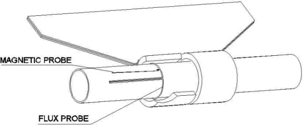
The excluded flux probe is compounded by a single one turn loop around the discharge tube and a magnetic field next to the loop (figure 1). Three sets were assembled at different axial positions. The high voltage signal of the loop was measured using a compensated voltage divider made with high precision wire resistors and electrolytic solution. In spite of measurement repeatability three discharge signals were used to calculate the mean value and to estimate the uncertainty.
The theoretical approach takes the ion as particle and electrons as mass-less fluid. The equation of motion of each species is:
w
E
w
H
-
P
c
e
dt
d
m
i=
+
×
(1)e
v
e eE
w
H
p
en
eP
c
en
dt
d
m
=
0
=
−
+
×
−
∇
−
(2)Figure 1. Schematic drawing of the experiment showing one set of the excluded flux probe.
where
f
i(
r
,
w
,
t
)
is the distribution function,n
i=
f
i(
r
,
w
,
t
)
d
3w
,w
d
t
w
r
f
n
i i ii
=
(
1
/
)
w
(
,
,
)
3v
,P
=
e
η
~
J
is the momentum transferred from ions to the electrons per ion per unit of time due to collisions, andη
~
is the resistive tensor calculated according to2
/
ne
m
eν
η
=
, ν the anomalous collision frequency andp
e=
n
ekT
e is the pressure. Field equations are Maxwell's equations without displacement current term. The numerical code uses particle-in-cell technique in 1.1/2 dimension (space-time r-t) [10]. The anomalous collision frequency was calculated according to evolution of lower hybrid drift previously verified as the most important of the micro instability present in the plasma [11]. The spatial grid had 30 elements where particles at t=0 were randomly distributed. For the present investigation we used 5000 particles and time steps of 5 ns. Due to the low dB/dt of the system the pinch evolves with a partially ionized gas and a broad current sheath profile in the discharge tube.2. Results and discussion
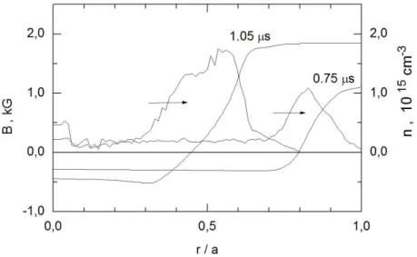
The external loop and magnetic probes show variation on the waveform during the first 1.5 µs of the rising of the current in the coil. That is approximately the period of existence of the plasmas, including the current sheath formation next to the discharge tube wall, its implosion, equilibrium and extinction. The lift off of the current sheath from the wall is about 0.4 µs. From this instant the external magnetic pressure becomes higher than the total plasma pressure (magnetic plus kinetic) and the radial implosion begins take place. So the partially ionized gas in the tube is dragged toward the axis of the system leaving behind a small portion of neutral particles. Part of these particles is ionized by fast electrons at the border of the current sheath and them they are dragged to the axis. That creates a current sheath with electrons and ions concentrated respectively at the internal and external regions of the current sheath. An electrostatic field in radial direction is formed with intensity comparable to the electric field in the azimuthal direction. That creates a broad profile on particle densities and due to the low temperature, a diffuse magnetic field occurs as shown in figure 2. At the end of implosion the minimum plasma radius is around r = a/2, where a is the discharge tube radius.
The radial dynamic of the implosion is shown by the time evolution of experimental excluded flux radius at midplane of the coil (figure 3). In that region the magnetic field lines are straight and this
radius is equal to the radius of the separatrix. The figure also shows the evolution of separatrix radius calculated from theoretical distribution of magnetic field in the discharge tube.
Figure 2. Radial profile of the magnetic field and electron density on early phase and at the end of the implosion.
The time lag between the instant of lift from the wall of the separatrix and the excluded radius is approximately within the estimated uncertainty on experimental time. After the lift off both radii reduce at same ratio. The mean speed of radial implosion is 5 ± 1 cm/µs and the experimental end of the implosion phase is around t= 1.1 µs. At this moment the configuration reaches the radius around one half of the inner radius of the discharge tube. The diffusion of external field starts to take place and the excluded flux radius reduces at speed 2 ± 1 cm/µs until t= 1.5 µs. The mechanism accelerates after this moment and the closed field line vanishes. Theoretically, the equilibrium phase shows a steady evolution with low amplitude radial magneto-acoustic. After the end of implosion the plasma the hot plasma expands radially. Since the external magnetic field is rising the external magnetic pressure promotes a second radial compression. On the simulation the process is interrupted due to high number of particles reflected by magnetic piston.
Figure 3. Evolution of the excluded flux radius at midplane of the coil (z= 0.0).
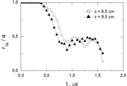
The time evolution of the excluded flux radius at end region of the coil has shown similar behavior of that at mid-plane of the coil. It is shown in figure 4, without the estimated error bars, for clarity. It shows that the displacement of the current sheath starts around the same time as at mid-plane. The final radius at the end of the implosion is about the same as well, around one half of the discharge tube radius. The excluded flux radius starts to reduce significantly after around t= 1.4 µs in the various axial positions inside the coil. That might indicate that the length of the plasma column extends beyond the limits of the coil. The applied diagnostic shows that the closed magnetic field line configuration is actually formed in the system. Therefore, the magnetic field reconnection process takes place outside the coil region. The configuration remains in equilibrium by the full length of the coil and is lost by radial diffusion or annihilation of the magnetic field.
Figure 4. Evolution of the excluded flux radius at the end region of the coil. The border of the coil is at z= 10.5 cm.
3. Conclusion
The formation and dimension of a field reversed configuration was investigated with excluded flux probes and numerical simulation of a hybrid code. At mid-plane of the coil the experimental excluded flux ratio was compared to the theoretical separatrix radius where turbulence was taken as associated with evolution of lower hybrid drift instability. Both radii were comparable, showing close values of the lift off time and radial speed during the implosion phase. The final radii at the end of the implosion were close as well, around one half of discharge tube radius. The excluded flux radius along the axial direction shows the same variation during the confinement as that at mid-plane of the coil. That suggests the formation of a plasma column that extends beyond the coil length with magnetic field line reconnection process taking place outside the coil. Measurement of local magnetic field will be done to check the topology of magnetic field lines at the end of the coil. In spite of the absence of mirror coils, the excluded flux measurements shows that the formation of a reversed field line configuration might occur in this short theta-pinch.
Acknowledgments
We are grateful to J.B. Galhardo for technical help and to Sao Paulo Research Foundation (FAPESP) and National Council for Scientific and Technological Development (CNPq) for financial support.
References