www.ann-geophys.net/27/1583/2009/
© Author(s) 2009. This work is distributed under the Creative Commons Attribution 3.0 License.
Annales
Geophysicae
Time-varying magnetotail magnetic flux calculation:
a test of the method
M. A. Shukhtina, E. I. Gordeev, and V. A. Sergeev
St. Petersburg State University, St. Petersburg, Russia
Received: 17 December 2008 – Accepted: 17 March 2009 – Published: 2 April 2009
Abstract. We modified the Petrinec and Russell (1996) al-gorithm to allow the computation of time-varying magneto-tail magnetic flux based on simultaneous spacecraft measure-ments in the magnetotail and near-Earth solar wind. In view of many assumptions made we tested the algorithm against MHD simulation in the artificial event, which provides the input from two artificial spacecraft to compute the magnetic flux F values with our algorithm; the latter are compared with flux values, obtained by direct integration in the tail cross-section. The comparison shows similar time variations of predicted and simulated fluxes as well as their good correla-tion (cc>0.9) for the input taken from the tail lobe, which somewhat degrades if using the “measurements” from the central plasma sheet. The regression relationship between the predicted and computed flux values is rather stable allow-ing one to correct the absolute value of predicted magnetic flux.
We conclude that this method is a perspective tool to mon-itor the tail magnetic flux which is one of the main global magnetotail parameters.
Keywords. Magnetospheric physics (Magnetotail; Solar wind-magnetosphere interactions)
1 Introduction
The magnetic flux circulation in the solar wind-magnetosphere system determines the dynamical regime of magnetosphere (Russell and McPherron, 1973). This regime depends on the balance between the magnetic flux, reconnected on the dayside magnetopause and coming to magnetotail from the solar wind, and the magnetic flux, re-connected in the magnetotail and transported to the dayside
Correspondence to:M. A. Shukhtina ([email protected])
magnetosphere. If the dayside reconnection rate exceeds the tail reconnection rate, magnetic flux is stored in the tail and the substorm growth phase is observed; the situation when the tail reconnection prevails corresponds to substorm expansion phase; if there is a balance between dayside and nightside reconnection rates, steady magnetospheric convection is realized. Thus monitoring of the magnetotail magnetic flux value is necessary to characterize the state of the magnetospheric system. However, until recently the knowledge about this quantity was very poor. The reason is that F is a global characteristic, which is difficult to infer from local observations.
Several approaches are possible to calculate the magnetic fluxF. First, its value may be determined from optical ob-servations of the polar cap (PC) area, as the PC magnetic field lines are believed to project to tail lobes. Recently rou-tine optical observation of large polar areas from Polar and Image spacecraft made available PC observation during long periods (Brittnaher et al., 1999; Hubert et al., 2006; Milan et al., 2007; DeJong et al., 2007). However, weak luminosity near the PC boundary combined with dayglow contamination may influence the accuracy of the PC boundaries determina-tion, the accuracy itself being difficult to estimate.
An alternative approach to magnetotail flux calculation was proposed by Petrinec and Russell (1996) (further PR96). Their method is based on tail lobe magnetic field observa-tions combined with time-shifted simultaneous solar wind measurements. Petrinec and Russell (1996) derived a sta-tistical formula to describe the tail radiusRT as a function
of the solar wind parameters and magnetotail spacecraft po-sition, allowing to compute the flux value asF=0.5π R2TBL,
whereBLis the measured lobe magnetic field. The analysis
of thisRT model showed its good correspondence with both
Meanwhile it has been established long ago that the tail ra-dius (as well asBLandF values) depends also on the state
of magnetosphere: all three variables grow during the sub-storm growth phase and decrease after the subsub-storm onset (e.g. Caan et al., 1973; Maezawa, 1975; Baker et al., 1994). The dependence ofBLandRT values on the magnetospheric
state as well as their dependence on external parameters was studied by Shukhtina et al. (2004) (further Sh04). They ob-tained the regression models for the F value as a function of solar wind parameters and X-coordinate in the tail for three different magnetospheric regimes: Quiet (Q), Steady Magne-tospheric Convection (SMC) and Substorm Onset (SO) sep-arately. Their results showed that the magnetic flux values for all three states are independent of the dynamic pressure
Pdand almost independent ofX, confirming thatF can be treated as a state variable for the magnetotail. While the Sh04 results displayed a substantial flux differences for the states considered, their approach still used a fixed model for any particular state and did not allow to follow the magnetopause changes and to compute the trueF variations. In the present paper we propose and test a modification of the PR96 algo-rithm, allowing one to calculate the actual time-dependent magnetic flux in the magnetotail.
Like the original Petrinec and Russell (1996) method, the modified algorithm (hereafter referred to as the SPR algo-rithm) uses a number of serious assumptions and approxi-mations, and thus needs a very detailed testing. Since the method is based on the MHD equilibria equations, the global MHD modeling provides the best and natural possibility for its verification. In this paper we compare F values, predicted by the SPR algorithm for different locations of the artificial spacecraft in the tail, with those obtained by direct integra-tion of the magnetic flux through the tail cross-secintegra-tion. To make certain that the SPR scheme really improves the orig-inal PR96 one, the computations using the PR96 algorithm are also presented.
2 Tail magnetic flux calculation
2.1 Description of the modified (SPR) algorithm
The method is based on the approximation of axisym-metric flaring magnetotail and uses the equations of one-dimensional pressure balance in the magnetotail (vertical balance across the current sheet)
BL2/2µ0=B2/2µ0+nkT , (1)
and across the flaring magnetopause:
0.88P dsin2α+BSW2 /2µ0+nSWk(Tisw+Tesw)=BL2/2µ0,(2)
whereBLis the equivalent lobe magnetic field, andαis the
flaring angle. The coefficient 0.88 in Eq. (2) is the ratio of the magnetosheath pressure to solar wind dynamic pressure for high Mach numbers (Newtonian approximation, Spreiter et
al., 1966). If theαvalue is known, one can calculate the tail radiusRT, which is necessary to compute the tail magnetic
flux.
The validity of Eq. (1) was tested experimentally in the midtail (Fairfield et al., 1981; Baumjohann et al., 1990; Petrukovich et al., 1999), and it was concluded that the ver-tical balance is approximately satisfied at distances tailward ofX∼−15RE(with some exceptions near substorm onset –
Petrukovich et al., 1999), where the “tail approximation” is fulfilled. Magnetic and plasma data on the RHS of Eq. (1) is taken from results of the MHD simulation.
The pressure balance across the magnetopause was stud-ied and confirmed experimentally in PR96. In Eq. (2) param-eters on the LHS are the solar wind paramparam-eters, time-shifted to theXcoordinate of the observational point. For simplic-ity we use the time shift1T=1X/Vsw, where 1X is the distance alongXbetween the observational points in the tail and in the solar wind. The electron temperatureTeswis as-sumed equal to the ion temperatureTisw. Comparison of results based on this assumption with those forTesw=2Tisw
(which is perhaps more appropriate – see Newbury et al., 1998) showed that they are almost identical due to the rel-atively small contribution of the thermal pressure to the LHS of Eq. (2). The solar wind dynamic pressure was calculated as Pd=1.94×10⁻⁶nSWVSW2 (assuming 4%-helium content,
e.g. Tsyganenko, 2002). Solving Eq. (2), we determine the flaring angleαvalue, necessary for the tail radiusRT
com-putation.
When calculating theRT value, the magnetosphere is
as-sumed axisymmetric (relative to theXaxis, the GSM coor-dinates are assumed everywhere). As tanα=dRT/dx, theRT
value may be calculated as
RT(X)=RT0+
X
Z
0
tanα(x)dx (3)
whereRT0 is the tail radius value at the terminator(X=0).
As shown in Petrinec et al. (1991), the radius at terminator is almost independent of IMFBZvalue, and following their
results we calculate theRT0value as
RT0=14.63(P d/2.1)−1/6
withPdgiven innPa, andX,RT andRT0inRE.
Here begins the difference of the present (SPR) procedure from the PR96 approach, where (as well as in Sh04) a large set of Eq. (2) for different conditions was solved to obtain model formulas forαandRT dependence on inputsPd, IMF
BZand spacecraft X-coordinate. After sin2α(X)dependence
is determined, the integral in Eq. (3) may be calculated, giv-ingRT andF values. One function for all situations was
de-rived in PR96, whereas in Sh04 different formulas for differ-ent states (Q, SMC and SO) were obtained. In the presdiffer-ent ap-proach theα,RT, andF values are calculated from Eqs. (1–
that is for any specific time. To use Eq. (3) one needs to specify theα(X)dependence. Based on previous experience, we express sin2α(X)as
sin2α=Aexp(CX) (4)
According to Sh04 this dependence fits well every of three states considered, the C values for Q, SMC and SO be-ing 0.0749, 0.0781 and 0.0612. For further calculations we use the average of these values,C=0.0714. Substitution of Eqs. (4) to (3) then gives:
RT(X)=RT0−(1/0.0357)(arcsin(Aexp(0.0357X))−arcsin(A)), (5) whereAis determined from Eq. (4).
The last thing to do is to take into account the BL and
αdistribution in the tail to match the observation point in-side the tail with the magnetopause point where the bal-ance is evaluated. One may expect that theBL-isocontour
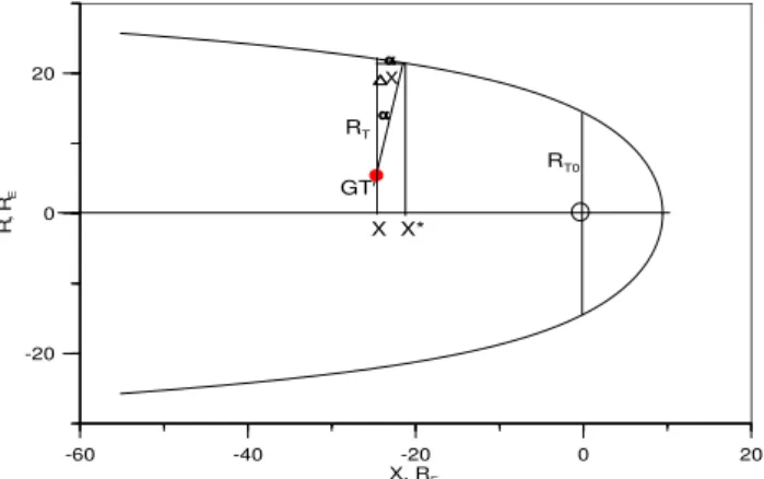
lines should be perpendicular to magnetopause in its vicin-ity, but should follow the linesX=const in the central sec-tor of the tail (this was confirmed by ISEE2 spacecraft ob-servations, see e.g. Fig. 3 in PR96). So the X value at the spacecraft (e.g., Geotail) position should be replaced by some newX∗value at the magnetopause which has the same BL value, X∗=X−1X, where 1X=(RT−(Y2+Z2)1/2)
sinαcosα,X, Y, Z being the coordinates of the observation point (Fig. 1, the same as Fig. 2 in PR96). SubstitutingX∗ to Eq. (4), we obtain the newA* value, which is then substi-tuted to Eq. (5) to get the newRT value, the new1Xvalue,
etc. After 3–4 iterations the solution converges, and finally
RT(X)=RT0−(1/0.0357)(arcsin(A∗exp(0.0357X))−arcsin(A∗)) (6) Finally, ignoring the depressed (compared to the lobe values) magnetic field inside the plasma sheet and suggesting the cir-cular tail cross-section, we approximate the tail magnetic flux as
F =0.5π RT2BL (7)
This procedure is repeated for any time step.
Thus the (modified) SPR algorithm of the magnetotail flux calculation requires a) knowledge of the BL value at
some point tailward−15RE (calculated from Eq. 1), and b)
knowledge of the sin2αvalue, which, according to Eq. (2), needs data on solar wind parametersPd,nSW,TswandBsw.
The solar wind parameters are inputs for MHD simulation, whereas plasma and magnetic pressures in the magnetotail are the results of the simulation.
Assumed pressure balance in the magnetotail and at the magnetopause (Eqs. 1, 2), the presumed axisymmetric mag-netopause shape (Eq. 6) and the neglected plasma sheet (Eq. 7) are all the approximations that may lead to systematic errors. The MHD simulation provides an excellent opportu-nity to test and correct the used approach. To do it, F values,
-60 -40 -20 0 20
X, RE
-20 0 20
R,
R
E GT
X
X X* RT
RT0
Fig. 1. The scheme, presenting the geometry of Geotail measure-ments. Xis the Geotail position,X∗is the magnetopause coordi-nate, corresponding to the sameBLandα values,RT is the tail
radius.
calculated by the SPR algorithm, are compared with the inte-gral of the magnetic flux through a magnetotail cross-section tailward−15RE(Flux Direct,FD).
2.2 Direct magnetic flux calculation
We have run the simulation at the Community Coordinated Modeling Center (CCMC), operating at NASA GSFC. Stan-dard global MHD code OpenGGCM was used, which solves the MHD equations with additional dissipation (see, e.g., Raeder, 2003) in the simulation domain [24,−350]REinX, |Y|<48RE,|Z|<48RE. Stretched Cartesian grid with step
size inX,Y andZ, changing from (0.25, 0.4, 0.25)REin the
plasma sheet to (0.25, 0.75, 1.1)RE at the magnetopause at
Xdistances from 10REto−30REwas used.
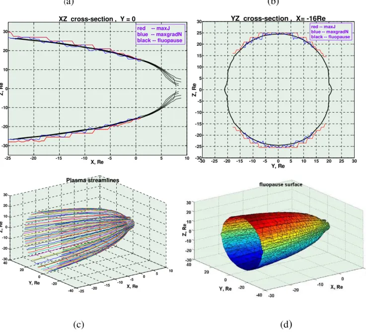
As our goal was tail magnetic fluxFcalculation, the most important thing was the accurate magnetopause identifica-tion. Different approaches to magnetopause determination have been discussed in the literature. We tried three dif-ferent methods, based on density gradient, current density peak (Garcia and Hughes, 2007), and fluopause (Palmroth et al., 2003) determination. Fluopause is defined as a family of plasma streamlines, starting in the solar wind and pass-ing most close to the x-axis on the nightside – see Fig. 2c and d. The streamlines are started from X=12RE with a
step size 0.5RE inY andZ. Figure 2a, b shows the
mag-netopause position, determined by 3 methods, in theXZ(for Y=0RE) andYZ(forX=−16RE) cross-sections. Thin black
lines in Fig. 2a show the fluopause positions for different Z start points, all lines joining on the nightside. Accord-ing to Fig. 2a, b all three methods agree for−25RE<X<0, |Z|>15RE region, where all of them provide reliable
(
a
)
(
b
)
(
c
)
(
d
)
-25 -20 -15 -10 -5 0 5 10
-30 -20 -10 0 10 20 30
X, Re
Z, R
e
XZ cross-section , Y = 0
red -- maxJ blue -- maxgradN black -- fluopause
Y, Re
Z, R
e
YZ cross-section , X= -16Re
-30 -25 -20 -15 -10 -5 0 5 10 15 20 25 30 -30
-25 -20 -15 -10 -5 0 5 10 15 20 25 30
red -- maxJ blue -- maxgradN black -- fluopause
-25 -20
-15 -10
-5 0
5 10
-40 -20 0 20 40 -30 -20 -10 0 10 20 30
X, Re Plasma streamlines
Y, Re
Z, R
e
Fig. 2. The positions of magnetopause surfaces, corresponding to different definitions, in theXZcross-section forY=0RE (a)andYZ
cross-section forX=−16RE(b); plasma streamlines(c)and fluopause surface(d).
the fluopause method is used hereafter as a proxy of the mag-netopause.
To calculate the flux value, theYZcross-sections of mag-netosphere inside the fluopause at fixedXwere considered. The area of each square cell 0.5RE×0.5REwas multiplied
by theBX value in the cell center. For cells, crossing the
magnetopause, the area of the part inside the fluopause was taken. The integral of these elementary flux values gives the total magnetic flux value through the given cross-sectionFD,
the flux calculated by the direct integration. It is used for testing the F values, predicted by the SPR algorithm, which is described in the previous section. The F values were
com-puted separately for Northern and Southern lobes, the differ-ence between them indicating the accuracy of FD
calcula-tions. In addition, using direct integration, we could evaluate the relative contributions to flux values from the lobes and the plasma sheet, which is ignored in the SPR.
3 Results
0 100 200 300
t, min
0.4 0.6 0.8 1
F,
G
W
b
-4 -2 0 2 4
IM
F
B
Z
, n
T
-40 -20 0 20 40
VZS
W
, k
m
/s
0 100 200 300
t, min
0 100 200 300
t, min
0.4 0.6 0.8 1
F,
G
W
b
-4 -2 0 2 4
IM
F
B
Z
, n
T
0 100 t, min 200 300
-40 -20 0 20 40
VZ
SW
, k
m
/s
0.6 0.7 0.8 0.9 1
FD, GWb
0.7 0.8 0.9 1 1.1
F,
G
W
b
SPR
F = 0.85FD + 0.24 N = 70 cc = 0.99
PR96
F = 0.36 FD + 0.53
N = 70 cc = 0.92
0.5 0.6 0.7 0.8 0.9
FD, GWb
0.5 0.6 0.7 0.8 0.9 1
F,
G
W
b
SPR
F = 0.91 FD + 0.18
N = 68 cc = 0.93
PR96
F = 0.28 FD + 0.47
N = 68 cc = 0.77
North FD
South FD
North SPR South SPR North PR96 South PR96
X=-15 R
EY=4 R
E, Z=± 10 R
EX=-25 R
E(
a
)
(
c
)
(
b
)
(
d
)
Fig. 3.Top: Magnetic flux values, calculated by different methods atX=−15RE(a)andX=−25RE(c)for “observational points” in the
tail lobes (Z=±10RE). Solar windBZandVZvariations, shifted to the observational point, are also shown. Bottom: comparison of flux
values, calculated by different methods forX=−15RE(b)andX=−25RE(d).
It was run for perpendicular dipole with following fixed solar wind /IMF parameters at the left boundary of the simulation box (X=24RE): N=5 cm−3, T=6×10⁴K,
V x=600 km/s, V y=0 km/s, Bx=3 nT, By=0 nT. The chang-ing inputs wereVZ andBZvalues, whose variations,
time-shifted fromX=24RE to spacecraft position by convection
time1t=1X/Vsw, are presented in Fig. 3. At the left
bound-ary BZ=−4 nT att=0, determining the initial state of the
magnetosphere; at t=1 min BZ sharply changed to +4 nT,
keeping this value till t=10 min, then abruptly turned to
−4 nT, conserving till t=60 min, and abruptly changed to +2 nT, remaining constant till the end of simulation. The VZ value was zero tillt=99 min, and then began to change
0.6 0.7 0.8 0.9 1
FD, GWb
0.4 0.6 0.8 1 1.2
F,
G
W
b
SPR , cc=0.67, F = 0.68 FD + 0.18 PR96, cc=0.57, F = 0.49 FD + 0.42
0 100 200 300
t, min
0.4 0.6 0.8 1 1.2
F,
G
W
b
FD
FSPRns
FPR96ns
-4 -2 0 2 4
IM
F
B
Z
, n
T
-40 -20 0 20 40
VZS
W
, k
m
/s
0 100 200 300
t, min
0 100 200 300
t, min
0.4 0.6 0.8 1 1.2
F,
G
W
b
FD
FSPR beta=1
FSPR beta=0.1
-4 -2 0 2 4
IM
F
B
Z
, n
T
-40 -20 0 20 40
VZSW
, k
m
/s
0 100 200 300
t, min
0.6 0.7 0.8 0.9 1
FD, GWb
0.4 0.6 0.8 1 1.2
F,
G
W
b
beta=1, cc=0.70, F= 0.82 FD + 0.16 beta=0.5,cc=0.70, F =0.79FD + 0.19
beta=0.1,cc=0.79, F =0.83FD + 0.18
X=-15 R
E, Y=4 R
ENeutral sheet ‘measurements’ Plasma sheet ‘measurements’
a
c
b
d
Fig. 4.Top: the same as in Fig. 3a, but for “observational point” in the neutral sheet(a)and in the plasma sheet(c). Bottom: comparison of F values, calculated by different methods, for the “observational point” in the neutral sheet(b), and in the plasma sheet with different beta values(d).
shown in Figs. 3, 4. The North-South-North IMF turning se-quence allows to simulate the effects of a substorm, whereas theVZvariations should change the position of the
magneto-tail neutral sheet (originally this simulation was undertaken to study the effect ofVZvariations on the neutral sheet
posi-tion – see Tsyganenko and Fairfield, 2004). Two magnetotail cross-sections, atX=−15RE andX=−25RE, were chosen.
Observation points in these cross-sections (locations of arti-ficial spacecraft in SPR) were taken in the lobes atY=4RE,
Z=±10RE(Fig. 3a and c). Results for the North and South
lobes are shown by a solid and dashed line correspondingly. The flux values in two lobes are very close: mean relative difference between North and SouthFD values is 0.4% and
3% atX=−15REandX=−25 REcorrespondingly; the SPR
algorithm gives 0.3% and 0.2% correspondingly.
Consider first the FD variations at X=−15RE, Fig. 3a.
Initially (till BZ southward turning) the FD value slightly
the initial value −4 nT to +4 nT. The subsequent 51-min interval of BZ=−4 nT (Vsw=600 km/s) was concluded by
FD decrease from∼0.9 GWb to∼0.65 GWb following the
IMF northward turning. During the negative BZ interval
(growth phase) FD increased from 0.78 to 0.91 GWb (not
monotonously, with a dip to 0.87 GWb, perhaps a pseudo-breakup).VZvariations, switched on after the simulated
sub-storm, are accompanied by low-amplitudeFDoscillations.
The predictedF demonstrates all kinds of variation, dis-played by direct flux calculation. However, theF values, given by SPR, exceed theFD ones by 0.1–0.2 GWb,
prob-ably due to the fact, that we ignored the existence of the plasma sheet, threaded by a smaller magnetic flux. The PR96 algorithm uses the mean modelRT(BZ) dependence, this
is why the predictedF values during the growth phase are lower than those provided by bothFDand SPR calculations.
Figure 3c displays flux variations atX=−25RE.
Accord-ing to all methods the flux values at X=−25RE are very
close to those atX=−15RE, being slightly (by∼10%) lower
due to partial magnetic flux closure across the equatorial cur-rent sheet. All methods demonstrate periodicF oscillations (synphase in both hemispheres) during the interval ofVz
vari-ations. Though the origin of these variations is unclear, they do not affect our testing of the methods.
Figure 3b and d demonstrates the relationship between F values, calculated by either SPR or PR96 algorithms, and FDvalues (here we use the average of the North and South
lobe fluxes). The correlation is better for the SPR method, than for PR96 one (cc=0.99 versus 0.92 forX=−15RE, and
0.93 versus 0.77 forX=−25RE). Averaging over two
cross-sections gives the regression equationsF=0.9FD+0.2 (SPR)
andF=0.3FD+0.5 (PR96) – Fig. 3b, d. Interestingly in both
figures the slope of the PR96 regression line is close to that of SPR one belowFD∼0.65–0.7 GWb, flattening at higher
flux values; so in this simulation the PR96 algorithm is not appropriate for high flux values. In whole the SPR regression is more realistic, its slope being closer to 1 with smaller free term. From Fig. 3 we conclude, that for artificial spacecraft in the tail lobes (at|Z|=10RE, where plasma beta<0.01) the
SPR method demonstrates a good correspondence with direct flux calculations, giving higher correlation and more realistic regression equations compared to PR96.
However, in many cases the magnetotail spacecraft, such as the Geotail spacecraft in recent years, is situated in the plasma sheet. Therefore we repeated the calculation for the same run, but putting the artificial spacecraft in the plasma sheet. In the top of Fig. 4 we present results of calculations at X=−15RE,Y=4REfor the “measurements” in the neutral
sheet (a) and in the plasma sheet, where plasma beta values are 1, 0.5 and 0.1 (c) (all points are within 5RE from the
neutral sheet). Now the correspondence withFD is worse
than in Fig. 3. The flux oscillations, predicted by empiri-cal algorithms, exceed those computed directly (FD). Note,
that the PR96 model was created for lobe spacecraft, under-estimating the difference between the neutral sheet
space-craft X coordinate and magnetopause X* value at the same BLisoline compared to SPR; this is probably the reason of
PR96 flux values exceeding the SPR ones in Fig. 4 contrary to Fig. 3 (lobe spacecraft). The cc values for the neutral sheet are 0.57 and 0.68 for PR96 and SPR algorithms corre-spondingly (Fig. 4b). In the plasma sheet the SPR algorithm givescc=0.70 for beta=1 and 0.5, andcc=0.79 for beta=0.1 (Fig. 4d). In spite of worse correlation the regression equa-tions for all spacecraft posiequa-tions are similar to those obtained for the lobes. Particularly, from Figs. 3, 4 we conclude, that for beta<1 the SPR algorithm gives a rather stable regres-sion equation:F=0.8FD+0.2 GWb (F=0.7FD+0.2 GWb in
the neutral sheet).
4 Discussion
We propose a modification of the PR96 method, allowing one to compute the time-varying magnetic flux in the magneto-tail. The modification is as follows: whereas in PR96 the tail radiusRT is calculated from statistically obtained model
for-mulas, which ignore the magnetotail magnetic flux change during substorms, in our approach (SPR) theRT value is
cal-culated from the pressure balance on magnetopause for ev-ery time step. The lobe magnetic field in both cases is taken from measurements (though in our calculations we also tried BLestimates obtained from the measurements in the plasma
sheet). The method is based on simultaneous measurements in the tail and solar wind at every time step; it uses many as-sumptions to make the problem tractable (neglects they−z magnetopause asymmetry and plasma sheet existence, as-sumes a specific shape ofBL isolines, uses the simplified
formula for the tail radius value at terminator, etc.) and, thus, requires a thorough testing. It is also necessary to compare both SPR and PR96 results with independent magnetic flux measurements to understand if our modification of PR96 re-ally gives a serious improvement.
Such independent magnetic flux “measurements” were taken from global magnetospheric MHD modeling, which allows to calculate for the given solar wind input all mag-netospheric parameters of interest, in particular, the value of the magnetotail magnetic flux. We predicted the magnetic flux values, using different positions of artificial spacecraft, and compared them with the calculatedFDvalues for two tail
cross-sections, atX=−15RE and atX=−25RE. When the
artificial spacecraft is situated in the tail lobes (atZ=10RE,
the correlation coefficients decrease, reaching minimum in the neutral sheet (0.7 and 0.6 for the SPR and PR96 cor-respondingly, Fig. 4). According to both algorithms the F variations are much larger, than theFD ones. However
for all spacecraft positions the SPR algorithm gives nearly the same regression equationF (GWb) = 0.8FD+0.2 GW.
The nonzero free term probably results from neglecting the plasma sheet existence in the algorithm; it is also probably the reason for the SPR values being on average larger (by
∼10–20%), than the FD ones. According to MHD
simula-tion the average plasma sheet (inside beta>1) contribusimula-tion to the tail magnetic flux is about 10%. The correlation coef-ficients grow with beta decrease fromcc=0.7 in the neutral sheet tocc=0.8 for beta=0.1 and tocc>0.9 for beta<0.01. Corresponding standard deviations are∼0.1 GWb (>10%) in the neutral sheet and∼0.01 GWb (∼1%) in the lobes. The stable regression equation makes possible to correct the pre-dictions as:Fcorr(GWb)=1.25F–0.25 in future applications.
The dependence of the calculatedF values on the spacecraft position needs a special study; it may result e.g. from the de-viations from 1-dimensional geometry in the presence of the magnetic flux closure through the plasma sheet (e.g. BBFs, plasmoids etc). We plan to explore it in the future studies.
In the present simulation a limited interval of solar wind/IMF parameters is considered. To do more general con-clusions we plan to study a wide range of input parameter variations.
5 Conclusions
An algorithm, suitable to compute the tail magnetic flux at any specific time, which is necessary for magnetospheric dy-namics monitoring, is proposed. The predictions of both modified (SPR) and original PR96 algorithms are compared with independent flux estimatesFD, obtained by direct
inte-gration of magnetic flux values through the tail cross-section in MHD-simulated magnetosphere. The test, based on MHD simulation of a 5-h interval with changing solar wind/IMF parameters, showed a good predictive efficiency of the SPR algorithm compared to the PR96 one, especially for the ob-servational point, taken in the tail lobe (cc>0.9 for SPR against 0.8–0.9 for PR96 atZ=10RE, where plasma beta
is <0.01). The correlation coefficients are weaker in the neutral sheet (0.7 and 0.6 for SPR and PR96 correspond-ingly), but the regression equation appears to be almost in-dependent of beta value (F=0.8FD+0.2 GWb againstF=0.4
FD+0.5 GWb), giving the opportunity to correct the SPR
pre-dictions.
Acknowledgements. We thank the developers of OpenGGCM global MHD simulation runs, which have been performed at CCMC through their public Runs on Request system (http://ccmc.gsfc.nasa. gov). The CCMC is a multi-agency partnership between NASA, AFMC, AFOSR, AFRL, AFWA, NOAA, NSF and ONR. We are grateful to Referee 1 for his interest to our work and fruitful
com-ments. We thank Marianna Holeva for her help in the paper prepara-tion. The work by M.S., E.G. and V.S. was supported by the RFBR grants 07-02-91703 and 07-05-91109.
Topical Editor I. A. Daglis thanks T. Nagai and another anony-mous referee for their help in evaluating this paper.
References
Baker, D. N., Pulkkinen, T. I., McPherron, R. L., and Clauer, C. R.: Multispacecraft study of substorm growth and expansion phase features using a time-evolving field model, in: Solar Sys-tem Plasmas in Space and Time, Geophys. Monogr. Ser., vol. 84, edited by: Burch, J. I. and Waite Jr., J. H., p. 101, AGU, Wash-ington, D.C., 1994.
Baumjohann, W., Paschmann, G., and Luhr, H.: Pressure balance between lobe and plasma sheet, Geophys. Res. Lett., 17, 45–48, 1990.
Brittnacher, M., Fillingim, M., Parks, G., Germany, G., and Spann, J.: Polar cap area and boundary motion during substorms, J. Geo-phys. Res., 104(A6), 12251–12262, 1999.
Caan, M. N., McPherron, R. L., and Russell, C. T.: Solar wind and substorm related changes in the lobes of geomagnetic tail, J. Geophys. Res., 78, 8087–8096, 1973.
DeJong, A. D., Cai, X., Clauer, R. C., and Spann, J. F.: Aurora and open magnetic flux during isolated substorms, sawteeth, and SMC events, Ann. Geophys., 25, 1865–1876, 2007,
http://www.ann-geophys.net/25/1865/2007/.
Fairfield, D. H., Lepping, R. P., Hones, E. W. Jr., Bame, S. J., and Asbridge, J. R.: Simultaneous measurements of magnetotail dy-namics by IMP spacecraft, J. Geophys. Res., 86, 1396–1414, 1981.
Garcia, K. S. and Hughes, W. J.: Finding the Lyon-Fedder-Mobarry magnetopause: A statistical perspective, J. Geophys. Res., 112, A06229, doi:10.1029/2006JA012039, 2007.
Hubert, B., Milan, S. E., Grocott, A., Cowley, S. W. H., and Gerard, J.-C.: Dayside ang nightside reconnection rates inferred from IMAGE – FUV and SuperDARN data, J. Geophys. Res., 111, A03217, doi:10.1029/2005JA011140, 2006.
Kawano, H., Petrinec, S. M., Russell, C. T., and Higuchi, T.: Mag-netopause shape determination from measured position and esti-mated flaring angle, J. Geophys. Res., 104, 247–261, 1999. Maezawa, K.: Magnetotail boundary motion associated with
geo-magnetic substorms, J. Geophys. Res., 80, 3543–3548, 1975. Milan, S. E., Provan, G., and Hubert, B.: Magnetic flux
trans-port in the Dungey cycle: A survey of dayside and night-side reconnection rates, J. Geophys. Res., 112, A01209, doi:10.1029/2006JA011642, 2007.
Newbury, J. A., Russell, C. T., Phillips, J. L., and Gary, S. P.: Elec-tron temperature in the ambient solar wind: Typical properties and a lower bound at 1 AU, J. Geophys. Res., 103, 9553–9566, 1998.
Newell, P. T., Liou, K., Sotirelis, T., and Meng, Ch.-I.: Polar ultra-violet imager observations of global auroral power as a function of polar cap size and magnetotail stretching, J. Geophys. Res., 106, 5895–5905, 2001.
Petrinec, S., Song, P., and Russell, C. T.: Solar cycle variations in the size and shape of the magnetopause, J. Geophys. Res., 96, 7893–7896, 1991.
Petrinec, S. M. and Russell, C. T.: Near-Earth magnetotail shape and size as determined from the magnetopause flaring angle, J. Geophys. Res., 101, 137–152, 1996.
Petrukovich, A. A., Mukai, T., Kokubun, S., Romanov, S. A., Saito, Y., Yamomoto, T., and Zelenyi, L. M.: Substorm-associated pres-sure variations in the magnetotail plasma sheet and lobe, J. Geo-phys. Res., 104, 4501–4514, 1999.
Raeder, J.: Global Magnetohydrodynamics – A Tutorial, in: Space Plasma Simulation, edited by: Buechner, J., Dum, C. T., and Sc-holer, M., Lecture Notes in Physics, vol. 615, Springer Verlag, Heidelberg, 2003.
Rybal’chenko, V. V. and Sergeev, V. A.: Rate of magnetic flux buildup in the magnetospheric tail, Geomagn. Aeron., 25, 378– 386, 1985.
Russell, C. T. and McPherron, R. L.: The magnetotail and sub-storms, Space Sci. Rev., 15, 205–266, 1973.
Sergeev, V. A., Pellinen, R. J., and Pulkkinen, T. I.: Steady Magne-tospheric Convection: a review of recent results, Space Sci. Rev., 75, 551–604, 1996.
Shue, J.-H., Chao, J. K., Fu, H. C., Khurana, K. K., Russell, C. T., Singer, H. J., and Song, P.: Magnetopause location under extreme solar wind conditions, J. Geophys. Res., 103, 17691– 17700, 1998.
Shukhtina, M. A., Dmitrieva, N. P., and Sergeev, V. A.: Quan-titative magnetotail characteristics of different magnetospheric states, Ann. Geophys., 22, 1019–1032, 2004,
http://www.ann-geophys.net/22/1019/2004/.
Spreiter, J. R., Alksne, A. Y., and Summers, A. L.: Hydromagnetic flow around the magnetosphere, Planet. Space Sci., 14, 223–248, 1966.
Tsyganenko, N. A.: A model of the near magnetosphere with a dawn-dusk asymmetry. 1. Mathematical structure, J. Geo-phys.Res., 107, 1179, doi:10.1029/2001JA000219, 2002. Tsyganenko, N. A. and Fairfield, D. H.: Global shape of the
mag-netotail current sheet as derived from Geotail and Polar data, J. Geophys. Res., 109, A03218, doi:10.1029/2003JA010062, 2004. Yang, Y.-H., Chao, J. K., Lin, C.-H., Shue, J.-H., Wang, X.-Y., Song, P., Russell, C. T., Lepping, R. P., and Lazarus, A. J.: Comparison of three magnetopause prediction models un-der extreme solar wind conditions, J. Geophys.Res., 107, 1008, doi:10.1029/2001JA000079, 2002.