B. NEDI
Ć
, D. JOVANOVI
Ć
, M.
Č
UPOVI
Ć
Tribological Processes of the Mechanisms
of Free Motion of Impulsive Friction
Variators
Free motion mechanism (FMM) of the impulsive variators is one vital part in power transmiting of impulsive lever variators which oscillating motion of external envelope (coulisse) converted in rotation movement of the output shaft. The elements of mechanism of free motion are exposed to friction and wear during the work, which may be extremely intensive in some cases. The paper analyzes the tribological processes on elements of free motion mechanism of impulsive friction variators with special report on wear of tribomehanical system: the external envelope (coulisse) - roller and roller - shaft (star).
Keywords: impulsive variators, free motion mechanism (FMM), tribological processes, wear,
1.
INTRODUCTION
Unlike other ways of transmission, energy does not transmit continuously, but in the form of periodic impulses. This transmitter makes two types of movements. Rotating motion with constant angular velocity of input shaft transforms into oscillatory motion of elements on the output shaft. Then the oscillatory movement by the mechanisms of free motion (FMM) transform into rotation movement of the output shaft. To reduce the problems caused by delays in transmission or an uneven speed during the construction several fit of transforma-tional mechanisms and (FMM) are connecting together. These mechanisms have been rotated in relation to one another for the Δϕ angle.
n 360°
= Δϕ
n introduce - number of fit of the mechanisms.
(FMM) with impulsive variations, converts oscilla-ting motion of the coulisse into rotating movement of output shaft [1]. Its consist of three main parts:
- exterior ring (the coulisse)
- input shaft (star), and
- rollers.
2.
TRIBOMECHANICAL SYSTEMS
IN FMM
According to its structure (FMM) belongs to a higher hierarchical class of the tribomechanical systems, because they can be subdivided in several basic tribomechanical systems [2, 3].
Figure 1. Free motion mechanism (FMM) 1 - coulisse, 2 - shaft, 3 - cylinder carrier,
4 - cylinder, 5 - spring
In FMM with impulsive variatiors (Figure 1), we distinguish the following tribomechanical systems:
• coulisse - roller,
• coulisse - cylinder carrier,
• coulisse - cylinder carrier (side contact),
• coulisse - capsule (side contact),
RESE
ARCH
Dr Bogdan Nedić1), Mr Desimir Jovanović2) Dr Milomir Čupović3)
1)
Faculty of mechanical engineering, Kragujevac, Srbija, [email protected]
2)
Zastava Arms AD, Kragujevac, Serbia
3)
• roller - shaft,
• roller - compression spring,
• roller - capsule (side contact),
• roller - cylinder carrier (side contact)
Table 1 shows an appearance of tribomechanical systems and their basic types of movement that appears. Following items affects on development of the tribologic processes in the contact zones of FMM:
• elements material quality,
• production technology of the contact surfaces,
• termochemical kind of processing,
• load of elements in contact,
• quality of lubricants and cooling liquids.
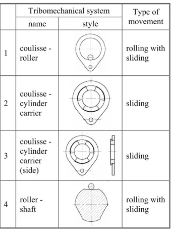
Table 1. Tribomechanical systems in FMM
Tribomechanical system
name style
Type of movement
1 coulisse - roller
rolling with sliding
2
coulisse - cylinder carrier
sliding
3
coulisse - cylinder carrier (side)
sliding
4 roller - shaft
rolling with sliding
Specific construction of FMM, complex operational conditions and a large number of influential factors causes that different kinds of friction occurs on FMM. Process that resists to relative motion of the object is used for the primary function and purpose of the transmitters. Friction in the FMM consists of: rolling friction with sliding, sliding friction, friction in the lubricant. Mutual complex connection makes difficult to analyze any kind of friction. Rolling friction with sliding occurs in process of wedging
the cylinder with external and internal envelope. It is partly caused by sliding in the triboelement contact zone and also with appearance of flexible hysteresis. Flexible hysteresis is caused by the deformation of loaded triboelements (rollers, external and internal envelope). Where by the resulting work of unload is only partially used for the motion and rest of it goes into heat. Sliding friction occurs in external envelope (coulisse) contact with the cylinder carrier. Under normal conditions of exploitation sliding friction in tribomechanical systems FMM is negligible compared to other types of friction. Friction and friction losses increases with increase of rotation number in FMM, viscosity and excess of the oil in contact [4, 5, 11, 12].
The following tribomechanical systems had biggest impact:
• coulisse - roller,
• coulisse - cylinder carrier,
• coulisse - cylinder carrier (side contact),
• roller - shaft (star).
On the elements of tribomehanical systems FMM can arise different kinds of wear and damages. On particular FMM may occur several types of wear but it is always the dominant one and it determines the future direction of development of the tribologic processes and finally lifetime of the FMM or pulse variator as its part. Which forms of wear occurs and which will be dominant depends on many factors: exploitation, construction, etc.
Determining the participation of certain types of wear in total wear of whole gear is very difficult. Visual quantification performs on the basis of appearance of the worn surfaces. The main criteria of working ability of cylindrical FMM impulse gear mechanisms is ability to wedge without traction and maintain the contact strength of most loading elements. FMM with cylindrical rollers gets out of order due to fatigue breakage and wear of the working surfaces star. FMM with an eccentric roller lost working ability due to destruction of the cylinder surface.
3.
DESCRIPTION OF EXPERIMENTS
Experimental testing of the power carrier impulse lever variator, with four types of transformation mechanisms and the FMM are conducted on specially made test table (figure 2).
Tested gear (2) was connected with the (1) driving aggregate over belted gear (4), (electric motor P=0.55 KN, n=2880 rpm). The brake disc was set on the output shaft of variator (6) that rotates in a magnetic field, of the electrical brakes (7) and thus made permanent load of the gear [8, 10].
Special measurement system was designed for tribometrical testing of the tribomehanical system FMM impulse lever, friction variator. The main components of that system are mentioned below:
• test table,
• device for analysis and measurement of surface roughness, TALYSURF 6,
• a device for wear measuring OPTON (ZEISS).
l
at
igid
1
4 5
2 6
Modem Bank Modem Bank 7
3 8
Figure 2. Schematic diagram of the test table
It was selected operational regime of the tested gear. The loading of the variator output shaft were achieved with brakes. Thus defined working conditions with a known geometry of the contact. After establishing the selected operational regime, carrier is put into operation a certain number of hours, then disassembly and measurement of the parameters of roughness and wear were performed. Tribomechanical systems of tested FMM (Table 1) where tribological processes are most affecting on the functioning of the mechanism and which changes were followed in the process of wear are:
• coulisse - roller,
• shaft - roller.
Changing the diameter of the hole on the coulisse ΔD = Di - D0 (Figure 3), were measured on the
computerized measurement device Opton (ZEISS). Measurement results are shown in Table 2.
Figure 3. Coulisse
Table 2. Coulisse hole diameter changing ΔD, mm
Element
name Operational time h
7 35 80 170 300
1 0,0058 0,0130 0,0168 0,0243 0,0397 2 0,0089 0,0160 0,0190 0,0261 0,0381 3 0,0070 0,0163 0,0230 0,0265 0,0327
Coulisse 4 0,0083 0,0150 0,0182 0,0257 0,0375
Figure 4. Appearance of wear coulisse
Time, h
Wear,
mm
0.00 0.01 0.02 0.03 0.04
0 50 100 150 200 250 300 350
Figure 5. Curve of coulisse wear
Figure 6. Places of measuring shaft wear Table 3. Values of shaft wear, h, mm
Operational time, h
7 35 80 170 300
0,0032 0,0040 0,0063 0,0162 0,0439 0,0026 0,0037 0,0067 0,0164 0,0420 0,0028 0,0042 0,0068 0,0178 0,0455
Figure 7. Appearance of wear cylinder shaft
Time, h
Wear,
mm
0.00 0.01 0.02 0.03 0.04 0.05
0 50 100 150 200 250 300 350
b a c
a - measuring point 1 b - measuring point 2 c - measuring point 3
Figure 8. Curves of shaft wear (star)
Measuring cylinder wear (a measure φ6) was performed by micrometer with prism TESAMASTER, measuring range from 0 to 25 mm measurement accuracy ± 0.001 mm. Change the cylinder diameter Δd = d0 - di , is given in table 4,
with:
d0 - cylinder diameter measurements before the
start operational,
di - cylinder diameter value measured after a
certain number of working hours of, FMM or variator.
Table 4 Changing of the cylinder diameter Δd,mm
Operational time h Element
name 7 35 80 170 300
cylinder 0,0028 0,0086 0,0110 0,0187 0,0410
Figure 9. Appearance of wear cylinder
Time, h
Wear,
mm
0.00 0.01 0.02 0.03 0.04 0.05
0 50 100 150 200 250 300 350
Figure 10. Curve of cylinder wear
Figure 11. Deformity coulisse caused by poor termochemical processing
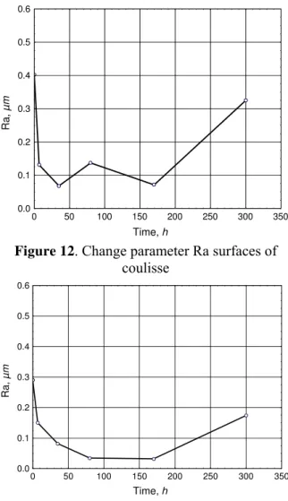
The images from 12 to 14 show the changes of the relevant parameter curves for observed elements roughness for tribomechanic systems of FMM impulse variators.
Time, h
Ra
, µ
m
0.0 0.1 0.2 0.3 0.4 0.5 0.6
0 50 100 150 200 250 300 350
Figure 12. Change parameter Ra surfaces of coulisse
Time, h
Ra,
µ
m
0.0 0.1 0.2 0.3 0.4 0.5 0.6
0 50 100 150 200 250 300 350
Figure 13. Change parameter Ra surfaces of cylinder
Time, h
Ra
,
µ
m
0.0 0.1 0.2 0.3 0.4 0.5 0.6
0 50 100 150 200 250 300 350
Figure 14. Change parameter Ra surfaces of shaft
4. THE ANALYSIS OF THE RESULTS
Elements of FMM during the operation are exposed to frequent changes of load and strong fatigue within materials of the entire system. The presence of cyclic strain fields causes appearance of fatigue in FMM, appearance of micro cracks, craters, as well as large plastic deformation, which can cause permanent damage and mechanism failure. Wear types of the observed tribomechanical system elements (cylinder, coulisse, and shaft) are: adhesive, fatigue and abrasive wear.
In shaft (star), the prevailing form of wear is fatigue wear (pitting) with a pronounced process of plastic deformation of the contact surface, which is a direct consequence of contact of the elements with different hardness (shaft 48 HRC, roller 62HRC), in conditions of high normal pressures, strains [10, 11].
Due to the relative movement of the cylinder over the shaft and large specific pressures that follows the process of wedging it comes to increasing plastic deformation of surface layers and to the appearance and increasing of micro defects in it. After the certain number of operational cycles or load cycles separation of small pieces of material from the surface may appear, which can cause increased abrasive wear on this elements. In order to reduce the intensity of fatigue wear it is desirable that the contact surface of the elements had the finest quality of surface.
loadings followed by frequent strikes due to unbalanced rotations of the external shaft. Oil film in contact of coulisse with roller and roller carrier is destroyed during the wedging process. As a result of that, increased wear in combination with material fatigue and very frequent gear overload leads to coulisse failure.
If we observe the curves, of wear and roughness parameters, we can noticed that smoothly work period of the surface, for most elements starts after about 50 operational hours. Then normal wear process begins. Start work smoothly period characterized the changing of the surface topography, because of transition technological topography in the experimental one. This process follows the sudden change in the roughness parameters, roughness peaks were taken and the profile becomes more unify. Due to high local loads, which are necessary for power transmission and friction motion, becomes changing roughness obtained after finishing contact surfaces.
At the beginning of the examination becomes an intensive removal of material from the surface what can be seen from the curves of wear. The most expressed peaks of roughness were taken away, so the profile becomes more equal and less rough. Roughness parameters reduced until the end of this period. This proves that the surface tends to become balanced in terms of topography. Period of normal wear begins after a start work smoothly period. Roughness parameters increase slightly, the surface had crossed in exploitation, and wear is settled. An exception is shaft witch roughness parameters increases sharply to about 200 operational hours. The curves of wear shows increased wear, which is consistent with the previous, and if it continues this trend of increase wear, may be normal to expect a quick switch of normal to destructive wear.
5. CONCLUSION
The appearance of tribologic processes on contact surfaces of the tribomehanic elements of FMM impulse friction variatiors is one of the main causes of loss of accuracy and work reliability. During the operational of these tribomehanic systems as the inevitable occurrence of the process of rolling cylinder between envelopes, rolling resistance appears. It has very complex nature and must be observed in the context of all causes and factors that affect on that. The dominant mechanism of wear on elements of the observed tribomehanic system is fatigue, and also adhesive and abrasive wear [8].
Wear intensity on elements of the observed tribomehanic systems is a function of the large
number of influential factors such as types and quality of surface and termohemcal processing, the size of the normal load and speed of relative movement between the basic, critical tribomehanic carrier systems [8, 10].
To reduce the wear on contact surfaces of the tribomehanic basic elements of (FMM impulse friction variators) and extended operational life of gear it is necessary to consider: the selection of material for triboelements, improve the contact surface topography, consider the economic confirmation for production of the FMM elements with hard plate on contact surfaces. Classic cylindrical roller replaced with convex cylinder. Under the load convex cylinders are compressed and they have the same shape of contact surface as the cylindrical. Also their dispose of load is very well, even at very high loads. Cylindrical roller are exposed to high tension concentration on the edge, which makes them very exposed up margin pitting and short life time. Convex cylinders are less exposed to wear, and also compensate possible deviations in the phase of construction and producing, even in conditions of high tensions as in the FMM.
REFERENCES
[1.] а в В.Ф.: М ха и и и
а и; "Mа ", ва; 1978.
[2.] а в В.Ф., а А. И., в в Е.
А.: К и а и ва и
и х а , П а
а ; "Mа ", ва;
1981.
[3.] А.E.: П ив а и и
-и ва иa а и; " а ", вa; 1988.
[4.] Bi-min Zhang Newby, Manoj K. Chaudhury, Friction in Adhesion, Langmuir, Vol. 14, No. 17. 1998, pp. 4865-4872.
[5.] Miloiu Gh., Dudita Fl.: Transmisii mecanice moderne; "Editura tehnica", Bucuresti; 1971. [6.] T. Pöschel, T. Schwager, N. V. Brilliantov:
Rolling friction of a hard cylinder on a viscous plane, European Physical Journal B, Vol. 10 (July 1999), pp. 169-174.
[8.] Jovanović D., Tanasijević S.: Mehanizam slobodnog hoda impulsnih varijatora, oblik i karakteristike, KOD’04, Novi Sad, 2004. [9.] Jovanović D., Nedić B., Čupović M.:
Influence of the technological heritage on life cycle of machine elements, 10th International Scientific Conference On Flexibile
Technologies, MMA2009, Novi Sad, 2009.
[10.] Jovanović D.: Tribološki procesi mehanizma slobodnog hoda impulsnih polužno - frikcionih varijatora, magistarska teza, Mašinski fakultet, Kragujevac, 2005.
[11.] Jovanović D, Tanasijević S.: Uticaj habanja na promenu ugla zaklinjavanja mehanizma slobodnog hoda impulsnih polužnih varijatora, IRMES'06, Banjaluka, 2006.