ISSN 1546-9239
© 2009 Science Publications
Corresponding Author: Hossein Shayeghi, Department of Technical Engineering, University of Mohaghegh Ardabili, P.O. Box 179, Ardabil, Iran
736
Robust Decentralized Control of Unified Power Flow Controller
1
Hossein Shayeghi and
2Ali Abdolalipour
1
Technical Engineering Department, University of Mohaghegh Ardabili, Ardabil, Iran
2
Technical Engineering Department, Kashan University, Kashan, Iran
Abstract: A new approach based on structured singular value is proposed for the robust decentralized Unified Power Flow Controller (UPFC) design. To achieve decentralization, using the schauder fixed point theorem the synthesis and analysis of Multi-Input Multi-output (MIMO) control system is translated into set of equivalent Multi-Input Single-Output (MISO) control system. Power systems such as the other industrial plants contain different kinds of uncertainties, which should be considered in controller design procedure. For this reason, the idea of µ-synthesis technique was used for designing of UPFC controllers. The proposed µ-based controller has a decentralized scheme and advantage of a decentralized controller design is reduction in the controller complexity and suitability for practical implementation. The effectiveness of the proposed control strategy was evaluated under operating conditions for damping low frequency oscillations in comparison with the classical controller to demonstrate its robust performance through nonlinear time simulation and some performance indices.
Key words: UPFC, decentralized control, µ-synthesis, facts, power system stability and control INTRODUCTION
As power demand grows rapidly and expansion in transmission and generation is restricted with the limited availability of resources and the strict environmental constraints, power systems are today much more loaded than before. In addition, the modern power system tends to be interconnected to obtain the most economic benefits. However, interconnection between remotely located power system give rise to occur low frequency oscillations on heavily loaded tie-lines especially after large or small disturbance in the range of 0.1-3.0 Hz. This causes the power systems to be operated near their stability limits. On the other hand, these oscillations constraints the capability of power transmission, threatens system security and damages the efficient operation of the power system. Thus, mitigation of low-frequency oscillations is necessary for secure operation of power systems. In recent years, the fast progress in the field of power electronics has opened new opportunities for the power industry via utilization of the controllable FACTS devices such as UPFC, TCSC and SVC which offer an alternative means to mitigate power system oscillations[1]. Because of the extremely fast control action associated with FACTS-device operations, they have been very promising candidates for mitigation power system oscillation in addition to improve power
system steady-state performance[2-3]. UPFC is regarded as one of the most versatile devices in the FACTS device family[4-5], has the capabilities of control power flow in the transmission line, improving the transient stability, mitigation system oscillation and providing voltage support. The application of the UPFC to the modern power system can therefore lead to more flexible, secure and economic operation[6].
Using the schauder fixed point theorem[14] the synthesis and analysis of the Multi-Input Multi-output (MIMO) control system under study is translated into a set of equivalent Multi-Input Single-Output (MISO) control system. It is shown that each decentralized controller can be designed independently such that performance of the overall closed loop systems is guaranteed. Based on this framework, a new decentralized controller is designed for satisfying UPFC performance based on µ-synthesis technique to mitigate low frequency oscillations. The µ-synthesis technique not only minimizes the maximum error energy for all command disturbance input, but also stabilizes the closed loop system for structured plant uncertainties with limited H norm. This especially is desirable when designing controllers for plants with unmodeld high frequency dynamics, or when the plants under go faulty operating conditions or plant parameters vary due to aging such as power system. The proposed control strategy is compared with the classical PID controllers to illustrate its robust performance under different operation conditions for damping low frequency oscillation and load disturbances. Finally, several three-phase fault and nonlinear time simulation results are shown to highlight the effectiveness of the proposed µ-based UPFC controller.
MATRIALS AND METHODS
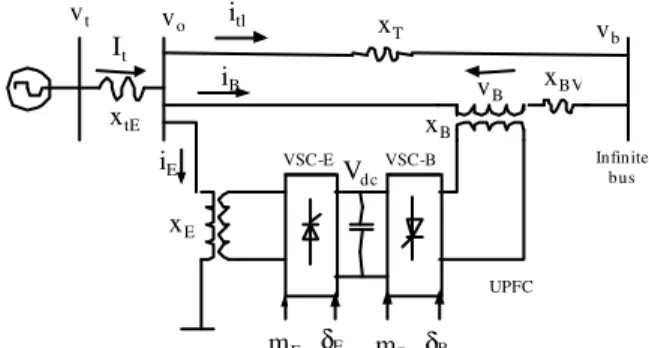
Figure 1 shows a SMIB system equipped with a UPFC. The UPFC consists of an Excitation Transformer (ET), a Boosting Transformer (BT), two three-phase GTO based Voltage Source Converters (VSCs) and a DC link capacitors. The four input control signals to the UPFC are mE, mB, Eand B, where, mE is the excitation amplitude modulation ratio, mB is the boosting amplitude modulation ratio, E is the excitation phase angle and B is the boosting phase angle.
Power system linearised model: A linear dynamic model is obtained by linearising the nonlinear model as given in[15-16] around an operating condition. The linearised model of power system as shown in Fig. 1 is given as follows:
∆δ•=ω0∆ω (1)
M / ) D P (−∆ e− ∆ω
= ω
∆ (2)
/ do fd q /
q ( E E )/T
E = −∆ +∆
∆ • (3) vo vt It xtE xE xT xBV itl iB xB Vdc
VSC-E VSC-B
iE Infinite
bus
vb
vB
mE δE mB δB UPFC
Fig. 1: SMIB power system equipped with UPFC
V T K E T 1 E A A fd A
fd=− ∆ − ∆
∆ • (4)
B b c B cb E e c E ce dc 9 / q 8 7 dc K m K K m K v K E K K v δ ∆ + ∆ + δ ∆ + ∆ + ∆ − ∆ + δ ∆ = ∆ δ δ • (5) Where: B b p B pb E e p E pe dc pd / q 2 1 e K m K K m K v K E K K P δ ∆ + ∆ + δ ∆ + ∆ + ∆ + ∆ + δ ∆ = ∆ δ δ B b q B qb E e q E qe dc qd / q 3 4 / q K m K K m K v K E K K E δ ∆ + ∆ + δ ∆ + ∆ + ∆ + ∆ + δ ∆ = ∆ δ δ B b v B vb E e v E ve dc vd / q 6 5 t K m K K m K v K E K K V δ ∆ + ∆ + δ ∆ + ∆ + ∆ + ∆ + δ ∆ = ∆ δ δ
K1, K2, K9, Kpu ,Kqu and Kvu are linearization constants. The state-space model of power system is given by:
x=Ax+Bu (6)
where, the state vector x, control vector u, A and B are:
] v E E [
x= ∆δ ∆ω ∆ q′ ∆ fd ∆ dc
T B B E
E m ]
m [
u= ∆ ∆δ ∆ ∆δ
738
D MS +
1
S W0
K1
K4 K5
K6
K2
K7
K8
STa
ka
+
1
/
1 STdo
K3+
Kpd
Kvd
Kvu
Kqd
Kqu
Kcu
Kp
1 K9
S +
Vref
∆ − −
− −
+ + + + + +
+
− +
+ −
− −
U
+
Pm
∆
/
Eq
∆
Vd
∆
∆ Pe
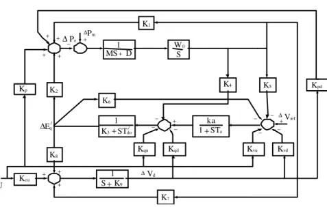
Fig. 2 Modified Heffron–Phillips transfer function model
) (t y1
) (t ym
X1
xm
) ( t u1
) (t um
) (t r1
) (t rm
P G
F
+
-+
Fig. 3. The MIMO control structure (m
×
m) system− −
− −
− −
− −
− −
− −
=
δ δ
δ δ
δ δ
δ δ
b c cb
e c ce
A b v A A
vb A A
e v A A
vc A
/ do
b q /
do qb /
do e q /
do qe
b p pb
e p pe
K K
K K
T K K T
K K T
K K T
K K
T K T
K T
K T
K M
K M
K M
K M
K0 0 0 0
B
The block diagram of the linearized dynamic model of the SMIB power system with UPFC is shown in Fig. 2.
Deecentralized control design: A centralized controller design is often considered not feasible for large-scale systems such as power system; in turn decentralized control is adopted. The advantages of a decentralized controller design are reduction in the controller complexity and suitability for practical implementation. Here, the problem of decentralized UPFC controller based on Schauder fixed point theorem[14] is translated into an equivalent problem of decentralized control design for a Input, Multi-Output (MIMO) control system. The basic MIMO comp-ensation structure for an m×m MIMO system is shown in Fig. 3. This consists of the uncertain plant P,
the diagonal compensation system Gand prefilter F. These systems are defined as follows:
= =
mm m2
m1
2m 22
21
1m 12
11
ij
P P
P
P P
P
P P
P
) s ]( P [
P(s) (7)
{
}
==
m 2
1
i
g 0 0
0 0 0
0 g
0
0 0 g
) s ( g diag
G(s) (8)
= =
mm 2
m 1 m
m 2 22 21
m 1 12 11
ij
f f
f
f f
f
f f
f
)] s ( f [ ) s (
F (9)
Here, it is developed a mapping that permits the analysis and synthesis of a MIMO control system by a set of equivalent MISO control system. This mapping results in m2 equivalent systems, each with two inputs and one output. One input is designated as a desired input and the other as a disturbance input. The inverse of the plant matrix is given by:
=
∗ ∗
∗
∗ ∗
∗
∗ ∗
∗
−
mm m2
m1
2m 22
21
1m 12
11
1
P P
P
P P
P
P P
P
The m2 effective plant transfer function is:
ij ij
ij
p adj
p det P
1 q
⋅ ⋅ =
= ∗ (11)
There is a requirement that det(P) be minimum phase. The Q matrix is then described by:
= =
∗ ∗
∗
∗ ∗
∗
∗ ∗
∗
mm m2
m1
2m 22
21
1m 12
11
mm 2
m 1 m
m 2 22
21
m 1 12
11
P 1 P
1 P
1
P 1 P
1 P
1
P 1 P
1 P
1
q q
q
q q
q
q q
q
Q (12)
Where:
] P
1 [ ] q [ Q , ] q
1 [ ] P [ P ], P [ P
ij ij ij
ij 1
ij ∗
∗
− = = = =
=
The matrix P-1 is partitioned to the following form:
] B
q 1 [ ] P [ P
ij ij 1
+ = = = ∗ −
(13)
where, is the diagonal part and B is the balance of P−1. The system control ration relating r to y is
PGF ] PG I [
T= + −1 . Pre-multiplying of system control ration by [I+PG] yields:
[I+PG]T=PGF (14)
When P is nonsingular, Pre-multiplying both sides of this Eq by P-1 yields:
[P 1 G]T GF
= +
−
(15) Using Eq. 21 and with G diagonal, Eq. 23 can be rearranged as follows:
T [ G]1[GF BT]
− +
Λ
= −
(16)
This is used to define the desired fixed-point mapping where each of the m2 matrix elements on the right side of Eq. 24 can be interpreted as a MISO problem. Proof of the fact that design of each MISO system yields a satisfactory MIMO design is based on the schauder fixed point theorem[14]. This theorem is described by defining a mapping Y(T) by:
11
f g1
1
1 1 q y1 1
1
−
1 1 d 1
r f12 g1
1
1 1
q y1 2 1
−
1 2
d
2 r
21
f g2
1
2 2
q y2 1
1
−
3 1 d 1
r f22 g2
1
2 2
q y2 2
1
−
2 2
d
2
r
1 3 f
1
1 3 y
1
−
3 r
23
f g2
1
2 2
q y2 1
1
−
1 3
d
1
g
1 1 q
3
r
2 3
d
31
f g3
1
3 3 q y3 1
1
−
1
r f3 2 g3
1
3 3 q y3 2
1
−
2 r
3 2 d
33
f g3
1
3 3 q y3 3
1
−
3 3
d
3 r
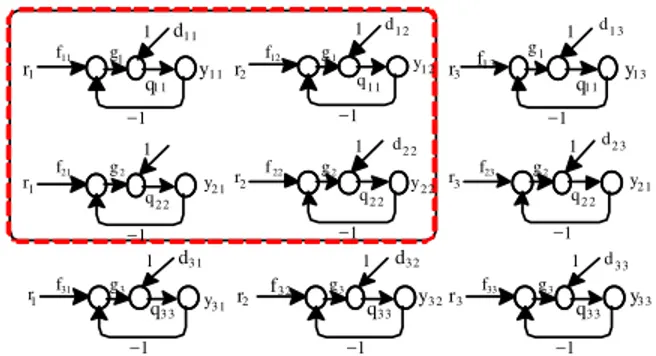
Fig. 4: Effective MISO loops 2×2(boxed-in loops) and
3
3× (all nine loops)
] BT GF [ ] G [ ) T (
Y = Λ+ −1 −
(17) where, each member of T is from the accepted set
ℑ. If this mapping has a fixed point i.e., T∈ℑ such that Y(T)=T, then their T is a solution of Eq. 16.
Figure 4 shows the four effective MISO loops resulting from a 2×2 system and the nine effective MISO loops resulting from a 3×3 system. Since and G are both diagonal, the (1,1) element on the right side of Eq. 17 for the 3×3 case, for a unit impulse input, yields the output:
)] q t q
t ( f g [ q g 1
q y
12 31 12 21 11 1 11 1 11
11 − +
+
= (18)
For each MISO system there is a disturbance input which is a function of all the other loop output. The object of the design is to have each loop track its desired input while minimizing the output due to the disturbance inputs.
740
Pe
Pm
Set point
KDC
1+sTw sTw Ms
1
−
+ dt
dδ
Block 1
1+sT1 1+sT2
Fig. 5: Transfer function block diagram of the UPFC based damping controller
mB mB
δE
Pe2 Pe2
P2×2
p1*
p2* Vdc
Vdc
d
d
δE
Fig. 6: MIMO system translated into MISO system
+ +
+
+
+ +
+
+
K wu ∆u
wd
wn
d r n
z
v
u
Nominal model of
system −
−
wc
wp
Fig. 7: The proposed synthesis strategy for UPFC controller
) 5 . 4 s )( 1 . 0 s (
) 656 . 3 s ( s 0145 . 536 controller Damping
+ +
+ =
We now proceed to design a decentralized power flow and DC voltage robust controller using the µ -synthesis technique. MIMO system shown in Fig. 6 decentralized into MISO system as shown in this. For each MISO system there is a disturbance input which is a function of all the other loop output. In fact, using the pervious mentioned procedure the UPFC power flow and DC voltage regulators controllers are designed independently based on µ technique with this decentralized method.
To achieve our objectives and according to -synthesis requirements, we propose the control strategy shown in Fig. 7 for a power flow and DC voltage. This figure shows the main synthesis strategy for obtaining the desired decentralized controller.
Usually, the uncertainties in power system can be modeled as multiplicative and/or additive uncertainties[17]. In Fig. 8 the u block models the unstructured uncertainties as a multiplicative type and
K G0
c
w wu wd
p w
n w 3
z 2 z
1 z v
r
+
− +
+ +
+
+
+
u
n v
d
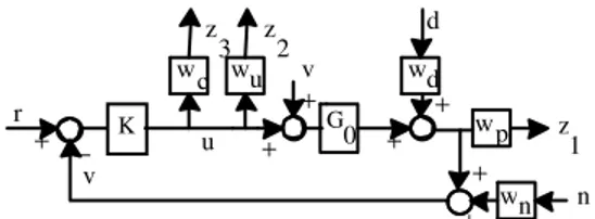
Fig. 8: Synthesis framework for UPFC controller Wu is the associated weighting function. According to the requirements of performance and practical constraint on control actions, the weighting functions Wc and Wp are added to the control area model. The weight, Wd at the input disturbances sat the normalized. The weight, Wn at the input noise sat the normalized. The next task is to isolate the uncertainties from the nominal plant model and redraw the system in the standard M- configuration[17]. We can redraw Fig. 7 as shown in Fig. 8.
According to Fig. 8, the and M for UPFC controller is given by:
) P , P , (
blockdiag∆u ∆ C ∆ P
=
∆ (19)
− −
− −
− −
=
− −
−
− −
−
1 0 0 d c 1 0 0 u 1 0 0 d c
1 0 0 n u 1 0 0 u 1 0 0 d u
0 n p 0
p 0
p d
G T W W G T W G T W W
G T W W G T W G T W W
T W W S
W S
W W
M (20)
To and So are complementary sensitivity and sensitivity functions of the nominal model of system and described by:
1
0 0
0
1 0 0 0
) KG 1 ( T I S
) KG 1 ( KG T
− −
+ = − =
+ =
(21)
Now, the synthesis problem is designing the robust control K(s) such that the Eq. 22 is fulfilled.
inf M 1
K µ≤ (22)
where, the structural singular value is defined as:
{
( ): ,det(I M ) 0}
min ) M ( 1
= ∆ − ∆ ∈ ∆ ∆ σ = µ−
∆ (23)
Furthermore, let:
M =supµ∆(M(jω)) ω
µ (24)
the given uncertainty structure . Using the performance robustness condition and the well-known upper bound for , the robust synthesis problem reduced to solve the following problem:
mininfsup (DM(j )D1) D
K
−
ω
ω
σ (25)
Or equivalently:
∞ −1 L
D
K inf DF(P,K)D
min (26)
By iteratively, solving for D and K (D-K iteration algorithm). Here D is any positive definite symmetric matrix with appropriate dimension and (.)denotes the maximum singular value of a matrix.
Based on the above discussion, this problem is solved by D-K iteration algorithm using the MATLAB
µ-synthesis toolbox[18]. It should be noted that the order resulting controller by this procedure is usually high. In order to decrease the complexity of computation in the case of high order power systems, appropriated model reduction techniques might be applied to the obtained controller model. In summary the synthesis procedures of the proposed strategy are:
Step 1: Formulation of the UPFC control problem as a decentralized control scheme and identify the state space model.
Step 2: Identify the uncertainty blocks and associated weighting functions according to dynamical model, practical limits and performance requirements.
Step 3: Isolate the uncertainties from the nominal area model, generate the u, PC and PP blocks and obtaining M- configuration to formulate the desired level of robust performance.
Step 4: Start D-K iteration algorithm using the µ -synthesis toolbox to obtain the optimal controller. Step 5: Reduce the order of the resulting controller by using the standard model reduction techniques and apply -analysis to the closed loop system with reduced controller to check whether or not the upper bound of remains less than one.
RESULTS AND DISCUSSION
For the nominal operation conditions (P = 1 pu, Q = 0.2 pu, Vt=1.032 pu), we can consider plant shown
in Fig. 8. P is transfer function of system with damping controller.
Weighting functions selection: Uncertainty weights selection: For robust control design, an open loop system is represented by nominal plant model Pnom(s) and the uncertainty set which covers the differences between Pnom(s) and reality of the physical system. Representation of unstructured uncertainty involved using frequency-domain bounds on transfer functions. A power system can possess a large number of topological configuration and steady-state operation points. Variation of these operations points can be viewed as a source of unstructured uncertainty in the nominal linear plant model. The percentage model uncertainty is represented by the weight WuPe and WuVdc which corresponds to the frequency variation of the model uncertainty. This weighting functions are chosen to cover the maximum uncertainly as follows:
1 s 50
s 3 W
e
up
+
= ,
1 s 50
s 5 W
dc
uV
+ =
Performance weights selection: in order to guarantee robust performance and satisfy the control objectives of SMIB and UPFC problem, we need to add for each of the control Pe2 and Vdc, a fictitious uncertainty block along with the corresponding performance weights WC and WP associated with the control effort and control error minimization, respectively. The selection of WC and WP entails a trade off among different performance requirements, particularly good regulation versus peak control action. More details on how these weights are chosen are given in[19]. Based on the above discussion, a suitable set of performance weighting functions for Pe2 and Vdc is chosen as:
) 15 0001 . s (
) 15 100 / s ( WP_Vdc
× +
+
= ,
1 s 1 . 0
s 8 . 0 WC_Vdc
+ =
) 4 . 0001 . s (
) 4 . 30 / s ( W
e
P _ P
× +
+
= ,
1 s 1 . 0
s 3 . 0 W
e
P _ C
+ =
2 . 0
Wd_Vdc =
,
Wn_Vdc =0.05,
Wd_Pe =0.1,
Wn_Pe =0.05742 Dam ping controller
kpi kpp+
-+ ++
Pe2ref
ω ∆
Pe2
mB
S
Fig. 9: PI- type power flow controller with damping controller
Vdcref
Vdc
s / K
Kdp+ di e
Fig. 10: PI-type DC-voltage regulator
of the first D-K iteration, yielding the values of about 0.935 and 0.995 on the upper bound on , respectively. Thus, the robust performance is guaranteed. The resulting controllers Kpe2(s) and Kvdc(s) are a dynamic type and have a high order (12th and 11th). The controllers are reduced to a 3rd and 5th order with no performance degradation using the standard Henkel norm approximation. The transfer functions of the reduced order controllers are given by:
) 10000 s )( 579 . 2 s ( s
) 1244 . 0 s )( 316 . 2 s )( 9 . 176 s ( 011 . 0 K
2 e
P
+ +
+ +
+ =
) 94 . 32 s 8 . 0 s )( 35 . 9 s )( 31 . 30 s ( s
) 203 . 3 s 9035 . 0 s )( 406 . 1 )( 88 . 2 s ( 22 . 30390
K 2
2 Vdc
+ + +
+
+ +
+ =
µ µ µ
µ-based controller evaluation: The effectiveness of the proposed µ-based controller under different cases is evaluated by time domain simulation to illustrate its robust performance in comparison with the Conventional UPFC (C-UPFC) controller. In conventional method, P-I type controller is considered for power-flow controller and DC-voltage regulator. Fig. 9 and 10 show the transfer function of the P-I type power-flow controller and P-I type DC-voltage regulator, respectively. The optimal parameters of the power-flow controller (kpp and kpi) and DC-voltage regulator (kdp and kdi) are obtianed using genetic algorithm[16] for operating condition 1 as listed in Appendix. Optimum values of the power-flow controller are obtained as kpp = 0.5385 and kpi = 1.8259.When the parameter of power-flow controller are set at their optimum values. The parameters of DC-voltage regulator are now optimized and obtained as kdp = 0.398 and kdi = 0.5778. The
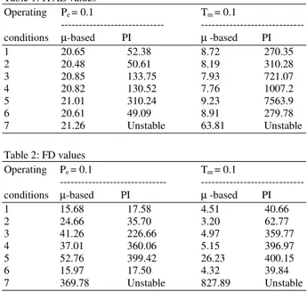
Table 1: ITAE values
Operating Pe = 0.1 Tm = 0.1
--- --- conditions µ-based PI µ -based PI
1 20.65 52.38 8.72 270.35
2 20.48 50.61 8.19 310.28
3 20.85 133.75 7.93 721.07
4 20.82 130.52 7.76 1007.2
5 21.01 310.24 9.23 7563.9
6 20.61 49.09 8.91 279.78
7 21.26 Unstable 63.81 Unstable
Table 2: FD values
Operating Pe = 0.1 Tm = 0.1
--- --- conditions µ-based PI µ -based PI
1 15.68 17.58 4.51 40.66
2 24.66 35.70 3.20 62.77
3 41.26 226.66 4.97 359.77
4 37.01 360.06 5.15 396.97
5 52.76 399.42 26.23 400.15
6 15.97 17.50 4.32 39.84
7 369.78 Unstable 827.89 Unstable
damping controller is considered with the same structure as given in previous section and conventional controllers are designed by application of cited damping controller.
The performance of the proposed µ-based UPFC and C-UPFC controllers with the damping controller mB following a 10% step change in reference power on line 2 and reference mechanical power, are and shown in Fig. 11 and 12 for power flow , DC voltage an frequency deviations. The loading condition and system parameters are given in Appendix.
To demonstrate performance robustness of the proposed control strategy, the Integral of the Time multiplied Absolute value of the Error (ITAE) and Figure of Demerit (FD) based on the system performance characteristics are being used as:
2 sw 2 w 2 w 20
0 1 e2 2 dc 3
T ) 10 US ( ) 10 OS ( FD
tdt ) w V w P w ( ITAE
+ × + × =
⋅ ω ∆ + ∆ + ∆ =
(27)
where, w1 =, w2 = 1000 and w3 = 1000, Overshoot (OS), Undershoot (US) and settling time of frequency deviation is considered for evaluation of the FD. The values of ITAE and FD are calculated for the different loading conditions as given in Appendix. Table 1 and 2 shows the damping performance of the robust and classical controllers.
0 5 10 15 0
0.02 0.04 0.06 0.08 0.1 0.12
P
e
T ime
0 5 10 15
-2 0 2 4 6 8 10
x10−3
Vd c
T ime
0 5 10 15
-1 0 1
x10−4
W
T ime
Fig. 11: Power system response for operation point 5 (Heavy loading) under Pe2fer=0.1 pu; Solid (µ-based) and Dashed (Conventional)
0 5 10 1
-3 -2 -1 0 1 2 3
Time
P
e
0 5 10 15
-0.03 -0.02 -0.01 0 0.01 0.02
Time
W
0 5 10 15
-0.4 -0.3 -0.2 -0.1 0 0.1 0.2 0.3
Time
Vd
c
Fig. 12: Power system response for operation point 7 (Very heavy loading) under Tm = 0.1 pu; Solid (µ-based) and Dashed (Conventional)
10
0 2 4 6 8
0.9998 0.9999 1 1.0001 1.0002 1.0003 1.0004 1.0005
t(sec)
W
0 2 4 6 8 10
0.999 0.9995 1 1.0005 1.001
t(sec)
W
(a) (b)
0 2 4 6 8 10
0.995
1
1.005
t(sec)
W
(c)
Fig. 13: Frequency deviation for a transitory 3-phase fault at the generator terminals, solid (m-based) and Dashed (Conventional). (a): For 5 ms duration under operation point 1, (b): For 10ms duration under operation point 1, (c): For 10ms duration under operation point 5
generator terminal is considered. Dynamic performance is obtained using the non-linear model under the system of the nominal and heavy loading condition with µ-based and optimal settings of the UPFC controllers (Power-flow controller, DC-voltage regulator and damping controller). Fig. 13 shows the power system responses under the above operation condition.
Remark 1: From the Fig. 11 and 12, it can be seen that the proposed µ-based UPFC controllers is very effective, achieve good robust performance and compared to C-UPFC have the best ability to damp power system low frequency oscillations.
Remark 2: Examination of Table 1 and 2 reveals that in comparison with the PI controllers, the system
performance is significantly improved by the µ-based controller designed for UPFC in this research against the loading conditions changes.
Remark 3: Figure 13 show the superiority of proposed
µ-based controller over its conventional counterpart. Also, effectiveness of the proposed control strategy in damping the local low frequency oscillations with UPFC is confirmed.
CONCLUSION
744 fixed point theorem. The motivation of using this control strategy is flexibility of the synthesis procedure for modeling uncertainty, direct formulation of performance objectives and practical constraints. Due to its practical merit, the proposed control strategy has a decentralized scheme. The advantages of this operation philosophy are reduction in the controller complexity by reducing the system size and suitability for practical implementation which is ideally useful for the real world complex power system. The time domain linear and nonlinear simulation results show that it achieve good performance for damping low frequency oscillations and improves the transient stability under different operating conditions and disturbances. The system performance characteristics in terms of ‘ITAE’ and ‘FD’ indices reveal that the proposed method is a promising control scheme for UPFC controller design and superior these of the classical controllers. Thus, it is recommended to generate good quality and reliable electric energy in the power systems.
REFERENCES
1. So, P.L. and T. Yu, 2000. Coordination of TCSC and SVC for inter-area stability enhancement. Proc. Int. Conf. Power Syst. Technol., 1: 553-558. DOI: 10.1109/ICPST.2000.900117.
2. Al-Awami, A.T., Y.L Abdel-Magid and M.A. Abido, 2007. A particle-swarm-based approach of power system stability enhancement with unified power flow controller. Elect. Power
Energy Syst., 29: 251-259.
DOI:10.1016/j.ijepes.2006.07.006.
3. Padiyar, K.R. and H.V. Saikumar, 2005. Coordinated design and performance evaluation of UPFC supplementary modulation controllers. Elect. Power Energy Syst., 27: 101-111. DOI:10.1016/j.ijepes.2004.08.010.
4. Gyugyi, L., 1992. Unified power-flow control concept for flexible ac transmission systems. IEE Proc. Gen. Transm, Distrib., 139:323-31. http://www.iet.org.
5. Hingorani, N.G. and L. Gyugyi, 2000. Understanding FACTS. IEEE Press, New York. 6. Huang, Z. and Y. Ni, 2000. Application of unified
power flow controller in interconnected power systems-modeling, interface, control strategy and case study, IEEE Trans. Power Syst., 15: 817-24. DOI: 10.1109/59.867179.
7. Stefanov, P.C. and A.M. Stankovic, 2002. Modeling of UPFC operation under unbalanced conditions with dynamic phasors, IEEE Trans. Power Syst., 17: 395-403. DOI: 10.1109/TPWRS.2002.1007909.
8. Tambey, N. and M.L. Kothari, 2003. Damping of power system oscillations with Unified Power Flow Controller (UPFC). IEE Proc. Gen. Transm. Distrib., 150: 129-40. http://www.iet.org.
9. Farsangi, M.M., Y.H. Song and K.Y. Lee, 2004. Choice of FACTS device control inputs for dam-ping interarea oscillations, IEEE Trans. Power Syst., 19: 1135-43. DOI: 10.1109/TPWRS.2003.820705. 10. Mishra, S., P.K. Dash and G. Panda, 2000. TS-fuzzy
controller for UPFC in a multi-machine system. IEE Proc. Gen. Transm. Distrib., 147: 15-22. http://www.iet.org.
11. Dash, P.K., S. Mishra and G. Panda, 2000. A radial basis function neural network controller for UPFC, IEEE Trans. Power Syst., 15: 1293-9. DOI: 10.1109/59.898104.
12. Vilathgamuwa, M., X. Zhu and S.S. Choi, 2000. A robust control method to improve the performance of a unified power flow controller. Electr. Power
Syst. Res., 55:103-11.
http://www.sciencedirect.com.
13. Pal, B.C., 2002. Robust damping of interarea oscillations with unified power flow controller. IEE Proc. Gen. Transm. Distrib., 149: 733-738. http://www.iet.org.
14. Horowitz, I.M., 1979. Quantitative synthesis of the uncertain multiple input-output feedback systems. Int. J. Control, 30: 81-106.
15. Wang, H.F., 1999. Application of modeling UPFC into multi-machine power systems. IEE Proc. Gen. Transm. Dist., 146: 306-12. http://www.iet.org. 16. Taher, S.T., S. Akbari, A. Abdolalipour and
R. Hematti, 2008. Design of robust UPFC controller using H control theory in electric power syst., Am. J. Applied Sci., 5: 980-989. http://www.scipub.org. 17. Shayeghi., H. and H.A. Shayanfar, 2006. Robust
decentralized LFC design in a restructured power system. Int. J. Emerging Elec. Power Syst., 6: Art. 4, http://www.bepress.com/ijeeps/vol6/iss2/. 18. Balas, G.J., J.C. Doyle., K. Glover, A. Packard and
R. Smith, 2006. The -Analysis and Synthesis Toolbox User's Guide for Use with MATLAB. The
Mathworks Inc., South Natick.
http://www.mathworks.com.