Design Of Monopole Antenna With U Slot
In Patch And Ground Plane Ideally Suited
For Wireless Applications
Diptanuprasad Chakraborty
Department Of Electronics Engineering KIIT University, 751024, Bhubaneswar, Odisha, India
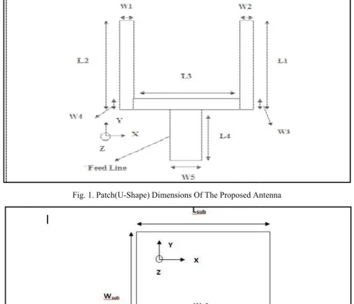
ABSTRACT- In this paper, a Monopole Antenna, square in shape, has been designed by cutting slots in both ground plane and patch for better impedance matching. The patch is assigned PEC material, and the substrate of the proposed antenna is Rogers RO3003(tm) having relative permittivity 3, and di-electric loss tangent of 0.0013. It is a Tri-band antenna having three resonant frequencies viz. 3.1GHz, 5.1GHz and 8.7GHz respectively, which exhibits same operating characteristics over a wider range of pass band. Comprehensive study of the frequency domain characteristics of the Antenna is being done, and is presented in this paper. The Antenna is simple and small in size, and is simulated using High Frequency Structure Simulator(HFSS) software. It is found to be suitable especially for Wireless Applications.
KEYWORDS- Monopole Antenna, Slotted Patch Antenna, Tri-Band Patch Antenna, U-shape Slotted Antenna, Inverted U-shape Slot, Square Monopole Antenna
I.INTRODUCTION
With the advancement in technology, designers are more often leaned towards designing newer technologies that can have a wider range of operation, but will be having a less complex structure. Antennas are being used in communication between systems, radar systems, microwave high resolution imaging and other data transmission systems having higher speed. A monopole antenna is a type of radio antenna in which the conductor is mounted over the ground plane perpendicularly, and is a resonant type of antenna whose length is specified by the wavelength of radio waves. In this paper, a patch antenna having three resonant frequencies has been presented, which consists of a U-Shape Slot both in patch and ground plane. The ground plane is being printed on the back side of the substrate parallel to the 50Ω feed line, and consists of inverted U-Slot which ultimately helps in better impedance matching and obtaining linear polarization and narrow vertical radiation pattern. The three resonant frequencies of 3.1Ghz, 5.1Ghz and 8.7Ghz bears good bandwidth and gain with S11<-10db.
In antenna design, the main issue that is to be considered is regarding the compact design of antenna that could cover the entire frequency band. Many antennas are being developed over the years, and experiments were already being carried out by putting different shape slots in the antenna for maximizing the impedance bandwidth and improving the gain of the antenna. The proposed antenna in this paper, consists of U-Shape slots that are mainly used for bandwidth enhancement and achieving multiple bands. U-Slots were first proposed by Lee and Huynh in the year 1995, and since then, experiments are being carried out, which has proven that these slots can provide dual and multi-band characteristics. The impedance bandwidth directly depends on the type of material being used on the substrate, and due to this, RO3003(tm) substrate having low di-electric constant was chosen. VWSR, Gain, Return loss and other important characteristics of the antenna are being studied, and presented in this paper. . U-Slots were first proposed by Lee and Huynh in the year 1995, and since then, experiments are being carried out, which has proven that these slots can provide dual and multi-band characteristics. The impedance bandwidth directly depends on the type of material being used on the substrate, and due to this, RO3003(tm) substrate having low di-electric constant was chosen. VWSR, Gain, Return loss and other important characteristics of the antenna are being studied.
Note: The monopole antenna was invented in 1895 by radio pioneer Guglielmo Marconi, for this reason it is sometimes called a Marconi antenna. Common types of monopole antenna are the whip, rubber ducky, helical, random wire, umbrella, inverted-L and T-antenna, inverted-F, mast radiator, and ground plane antennas
II.ANTENNA DESIGN
consist o the subst the groun resonant relation: The slot input imp the three & W2) an Current which in Bandwid by perfor Specifica Lsub= 18m L1= 8.2m Note: Th The side illustrated
of a patch in w trate exactly p nd plane dime radiator, and [Zd x Zs= ƞ2
/4 helps in matc pedance, and rectangle sha nd 0.4mm(W3
paths(Surface nduces three dth and gain en
rming parame
ations Of The mm, Wsub= 12 mm, L2= 8.2m he dimensions
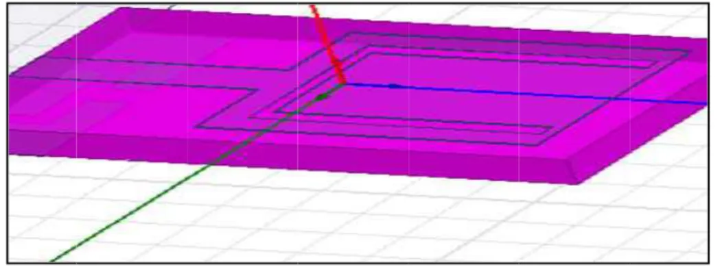
view of the p d below in Fig
which a U-Sha parallel to the ension are 12m
the impedanc 4], where 'ƞ ' i ching the patc also determin aped slots that 3 & W4), and e current) of resonant mod nhancement i tric study. Fig
Fig. 1
Fig. 2. G
e Proposed A 2mm, Wgnd= mm, L3= 6mm
of the propos proposed Mic g. 3.
aped slot is be feed line. Th mm and 3mm ce of the slot(Z
is the intrinsic ch with the fee
nes the radiati t are being cu d lengths of the
three resonan des and impr s also achieve g.1 below show
1. Patch(U-Shape
Geometry Of The
Antenna are il 12mm, Lgnd=3 m, L4= 7mm, W
sed antenna w rostrip Patch
eing cut, and he substrate w
respectively. Zs) is related w c impedance o
ed line for a w ion pattern di ut in order to f e three blocks nt frequencies roves the cap ed, and the op ws the geome
) Dimensions Of
e Ground Plane(W
llustrated bel 3mm, Ls1= 1 W1= 0.7mm, W were being foun
Antenna depi
a ground plan width is 12mm The U-shape with the comp of free space.
wider range o istribution of form the U-sh s are 8.2mm(L are formed d pacitance betw ptimal dimens etrical descript
f The Proposed An
With U-Slot)[Bac
low:
1.2mm, Ws1= W2= 0.7mm, nd out by para icting the plac
ne that is loca m(Ws), and len
slot in the gro plementary dip
of frequencies the proposed hape slot in th L1 & L2) and due to the slo ween ground sion of the des
tion of the pro
ntenna
ck View]
= 1.2mm, Ls2= W3= 0.4mm, ametric study. cement of gro
ated on the bac ngth is 18mm ound plane beh pole antenna(Z
by producing antenna. The he patch are 0.
6mm(L3). ot in the grou d plane and t signed antenn oposed antenn
= 0.7mm, Ws , W4= 0.4mm
.
ound plane an
ck side of m(Ls), and haves as a Zd) by the
g resistive e width of .7mm(W1
und plane, the patch. na is taken na.
s2= 6mm, .
Consider Software assigned, The Simu
Inverted bandwidt patch has gain enha parametr
Fig. 4 an distance, wide ban
A. From Re
ring the dimen e, and simulat
, and the ante ulated antenna
U-Shape Slot th. The basic s a width . Th ancement is a ric study.
nd Fig. 5 dep the sizes of U ndwidth have b
Observations turn Loss Cur
Resonant Fr
S11(In db) [R
Bandwidth(B
Fig
nsions mentio ted after app enna simulatio a is shown in
t was introdu antenna struc e patch is con also achieved,
picts the Side U-shaped notc been optimize
I
rve:
equencies Ob F1(In GH Return Loss O S11(F1)= B.W)[In GHz
g. 3. Side View I
oned in Fig. plying correct on was being
"Fig. 4 & Fig
Fig. 4. Side Vi
uced in the gr cture consists nnected to a fe , and the optim
Fig. 5. Top Vi
and Top Vie ch, and the siz ed by parametr III. OBSERV
btained: Hz)= 3.10GHz Or Reflection
-38.22db, S11 z]:
Illustration Of Th
1 & Fig. 2, t port assignm carried out a . 5" below.
iew Of The Anten
round plane in of a square p eed line of wid
mal dimension
iew Of The Anten
ew of the ante zes of two rec
ric analysis. VATIONS AN
z, F2(In GHz) Co-Efficient 1(F2)= -20.69d
he Proposed Anten
the proposed ment(Wave po after assigning
nna(Simulated)
n order to obt patch, a feed l
dth and length n of the desig
nna(Simulated)
enna simulate ctangular slots
ND RESULT
)= 5.10GHz, F t]:
db, S11(F3)= -nna
antenna is be ort). Proper A g all the desig
tain better im ine, and a gro h , as shown in gned antenna
ed in HFSS S s in the antenn
S
F3(In GHz)= 8 -37.61db
eing designed Air Box(Vacu
n parameters
mpedance matc ound plane. T n Fig.1. Bandw
is taken by pe
Software. The na’s patch to o
8.7GHz
d in HFSS uum) was correctly.
ching and The square width and erforming
B.W(F1)= 0.89GHz, B.W(F2)= 0.83GHz, B.W(F3)= 3.10GHz. Gain(G)[In db]:
G(F1)= 8db, G(F2)= 6.20db, G(F3)= 3.25db Radiation Efficiency: 2.46
Important Note: The solution frequency is fixed at 2.45GHz for all the cases.
B. Results
Return Loss:
Fig. 6. Return Loss Of The Proposed Antenna
The return loss graph is shown in Fig. 6. The three resonant frequencies here are 3.1GHz, 5.1GHz and 8.7GHz respectively. The bandwidth in case of first and second resonant frequency is higher, and Gain is higher at two resonant frequencies viz. F2= 5.10GHz and F3=8.7GHz.
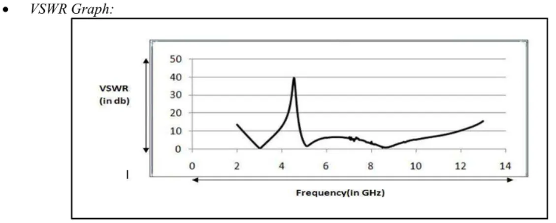
VSWR Graph:
Fig. 7. VSWR of Antenna(U-Shape Slot In The Ground)
The Voltage standing wave ratio(VSWR) of the proposed antenna is shown in Fig. 7. VSWR signifies how well the antenna is matched with the transmisssion line. It can be seen that highest value of VSWR is obtained at a frequency of 4.5GHz(40db), and the lowest value of the same is obtained at a frequency of 8.4GHz.
Y-ParameterY(1,1) vs. Frequency Curve:
Fig. 8 sh called as describes number o 54.707db Radiation function antenna i through t In genera the anten phi=90 d The elec radiation shows th The H-P patch jun edge of t
hows the Y pa s the admittan s the behaviou of ports. It c b).
Radiation Pa
n pattern of a of the directi is being obser the 3D pattern al, radiation p nna. The E-pl degrees. Both E
ctric field or n pattern is ali e radiation pa
lane radiation nction allow t the patch and
arameter vs. F nce is the com ur of any linea can be seen th
ttern:
an antenna de ion away from rved in antenn n through the m pattern refers t
ane Antenna E-plane and H
"E" plane de igned in one attern of the pr
n pattern look the alternating
hence formin
Frequency cur mplex ratio be ar electrical n hat the highe
efines the var m the antenna na's near field. maximum val to the directio
pattern resem H-Plane radiat Fig. 9(a). etermines the direction, and roposed anten Fig. 9(b).
ks like a dumb g current to e ng a magnetic
rve of the pro etween a curr
etwork that is est value of V
riation of the a. The power v
Principal Pla ue of the patte onal dependen mbles phi= 0 d
tion pattern is
. E-Plane Radiati
e polarization d is also refer nna at 2.45GH
. H-Plane Radiati
bbell shape st enter the anten
field pattern
oposed monop rent and a vol s generally reg VSWR is obt
total power t variation as a ane patterns c ern or by direc nce of the stre degrees, and
shown in Fig
on Pattern
or orientatio rred to as Ver
z.
ion Pattern
tructure(bi-dir nna and leave having field m
pole antenna. ltage. A Y-pa garded as a bl tained at a fr
that is radiate a function of t can be obtaine ct measureme ength of radio H-Plane radia .9(a) and 9(b)
on of the rad rtical radiation
rectional patte es the antenna maxima at the
The Y-param arameter matr
ack box consi equency of 4
ed by the ant the arrival an ed by making t ent.
o waves from ation pattern r ) below.
dio wave. The n orientation.
ern) since the a through the e radiating ed
meter, also rix mainly isting of a
direction to dipole of the pro The radia pattern is
Fig. 9(c) pattern is
The 3d p Omni-dir
Note: El circulatin
A triple b operates performa of operat impedanc antenna analyze t used for v
n of radiation a antenna (i,e X oposed antenn ation pattern o s achieved in F
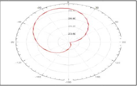
shows the ra s achieved her
3d Polar Plot
olar plot of th rectional patte
ectric field lin ng around the
band small an in three di ance in terms o
tion of wideb ce matching, is presented i the antenna in various wirele
and field mini XZ) and the p na at 2.45GHz of the propose Fig. 9(b) and f
Fig.
adiation patter re. Good radia
t:
he proposed an ern in the midd
Fig
nes from one e antenna follow
nd simple Mon screte freque of Gain, Band band antennas but also redu in this paper, n details. Band
ess application
ima at the cen polar pattern w z.
ed antenna is s fig. 9(c). The
9(c). Radiation P
rn of the prop ation behaviou
ntenna is show dle portion.
g. 10. 3d Polar Plo
end of the ant w the H plane IV. nopole Anten encies viz. 3 dwidth and Ra s. Slots used uces the size and numeric dwidth achiev ns.
tre of the patc will be O shap
shown in "Fig Radiation Pat
Pattern(Rtotal) Of A
posed antenna ur is exhibited
wn in "Fig. 10
ot(U-Shape Slot I
tenna to the o e.
. CONCLUSI nna has been d 3.1GHz, 5.1G adiation efficie in Patch and of the antenn cal study of t ved in this cas
ch. The H plan ped. Fig. 9(b)
. 9(a, b and c) ttern is shown
Antenna(At 2.45G
a simulated at d within the wi
" below. The
In The Ground Pl
ther follow th
ION
demonstrated GHz and 8.7 ency has been ground plane na to a greater the antenna is se is quite high
ne in this scen shows the
H-)". Nearly Om n for frequency
GHz)
t 2.45GHz. N ireless applica
pattern is alm
lane)
he E-plane wh
in this paper. 7GHz respect n obtained with
e of the anten r extent. The s then being
h, and the ant
nario will be o -Plane radiatio
mni-directional y of 2.45GHz
Nearly Omni-d ations frequen
most getting eq
hile magnetic f
The propose tively. Good
hin the accept nna not only complete stu carried out in tenna can pref
ACKNOWLEDGEMENT
I want to thank Dr. Subhrakanta Behera(Ass. Prof, School Of Electronics Engineering, KIIT University) for all his valuable suggestions and advice. Also, I am grateful to all the faculty members of School Of Electronics Engineering, KIIT University for all their support.
REFERENCES
[1] M. J. Ammann, “Impedance bandwidth of the square planar monopole,” Microw. Opt. Technol. Lett., vol. 24, no. 3, pp. 185187,Feb. 2000.
[2] R. Zaker, C. Ghobadi, and J. Nourinia, “Novel modified UWB planar monopole antenna with variable frequency band-notch function,” IEEE Antennas Wireless Propag. Lett., vol. 7, pp. 112–114, 2008.
[3] A. J. Kerkhoff, R. L. Rogers, and H. Ling, “Design and analysis of planar monopole antennas using a genetic algorithm approach,” IEEE Trans. Antennas Propag., vol. 52, no. 6, pp. 1768–1771, Jun 2004.
[4] Werner Wiesbeck, Grzegorz Adamiuk and Christian Sturm, " Basic Properties and Design Principles of UWB Antennas", Student Member IEEE.
[5] B. Saidaiah, A. Sudhakar, K. Padma Raju, "Circular Disk Monopole Antenna For Broadband Applications", International Journal Of Scientific And Research Publications, Volume 2, Issue 6, June 2012.
[6] Niazul Islam Khan, Anwarul Azim, Shadli Islam, "Radiation Characteristics Of A Quarter-Wave Monopole Antenna Above Virtual Ground", Journal Of Clean Energy Technologies, Volume 2, Number 4, October 2014.
[7] Rekha P. Labade, Shankar B. DeoSarkar, Narayan Pisharoty, "Square Printed Monopole Antenna For Wireless Applications", International Journal of Electrical, Computer, Energetic, Electronic and Communication Engineering, Vol:8, No:1, 2014.
[8] J. Jung, W. Choi, and J. Choi, “A compact broadband antenna with an L-shaped notch,” IEICE Trans. Commun., vol. E89-B, no. 6, pp. 1968–1971, Jun. 2006.
[9] R.A. Sadeghzadeh-Sheikhan, M. Naser-Moghadasi, E. Ebadifallah, H.Rousta, M. Katouli, B.S Birdee, "Planar Monopole Antenna Employing Back-Plane Ladder Shaped Resonant Structure For Ultra-Wideband Performance", IET Microwaves, Antennas & Propagation, 25th November, 2009.
[10] P. Jithu, A.Paul, V. Pithadia, U.P Khot, R. Misquitta, "Dual Band Monopole Antenna Design", International Journal Of Engineering And Technology(IJET).
[11] Yaoyao Cui, Yunqing Sun, Yang Li, Hongchun Yang, Xingliang Liao, "Microstrip Fed Monopole Antenna For UWB Application", Antennas, Propagation and EM Theory, 2008. ISAPE 2008. 8th International Symposium, 2-5 Nov. 2008.
[12] Xuelin LIU, Xiaolin YANG, Fangling KONG, University of Electronic Science and Technology China, "A Frequency-Reconfigurable Monopole Antenna with Switchable Stubbed Ground Structure", Radio Engineering, Volume 24, No.2, June 2015.
AUTHORPROFILE