Brazilian Microwave and Optoelectronics Society-SBMO received 9 Aug. 2011; for review 18 Aug. 2011; accepted 19 April 2012
Brazilian Society of Electromagnetism-SBMag © 2012 SBMO/SBMag ISSN 2179-1074
On the Design of Tree-type Ultra Wideband
Fractal Antenna for DS-CDMA System
Raj Kumar and Prem Narayan Chaubey (M.Tech. Student) Microwave and Millimeter wave Antenna Lab.
Defence Institute of Advanced Technology (DU), Girinagar, Pune-411025 Email: [email protected]
Abstract – This article describes the CPW-feed ultra wideband tree type monopole fractal antenna and it’s backscattering. The prototype antenna is fabricated with optimized dimension. The experimental result of this antenna exhibits the ultra wideband characteristics from 5.0 GHz to 14.0 GHz. The experimental and simulated results are in good agreement. The effects of various design parameters on impedance bandwidth have also been studied in detail using EM simulator. The nature of H and E – plane radiation patterns are omni-directional and bidirectional respectively. The measured group delay is almost constant throughout band. This indicates the phase linearity. The monostatic RCS of antenna is also simulated iteration-wise for antenna and structural scattering mode. This antenna can be useful for UWB system, Microwave Imaging and vehicular radar and military high data rate wireless communications.
Index Terms – Planar Monopole antenna, Fractal Geometry, CPW- Feed,
Group Delay and UWB system and backscattering.
I. INTRODUCTION
The Ultra wideband (UWB) technology opens new door for wireless communication system, since the current wireless system increasing exponentially. Recently, UWB technology with an extremely wide frequency range has been proposed for imaging radar, communications, and localized applications [1]. In 2002, Federal Communication Commission (FCC) authorized unlicensed use of UWB band ranging from 3.1 GHz to 10.6 GHz. In this, there are two main approaches for UWB system i.e MB-OFDM (Multi-Band Orthogonal Frequency Division Multiplexing) and DS-CDMA
(Direct-Sequence Code Division Multiple Access). The DS-CDMA approach uses three spectral
modes of operation, low band (3.1–5.15 GHz), high band (5.825–10.6 GHz), and multi-band (low
band plus high band) while MB-OFDM approach divides its full band 3.1–10.6 GHz into 14
sub-bands with each bandwidth of 528 MHz. Each sub-band consists of 128 tones and is modulated with
OFDM. The DS-CDMA approach uses high band (5.825 GHz - 10.6 GHz) as a mandatory mode
[2-3]. In this article, we will focus on the UWB antenna design for the DS-CDMA system over the
frequency range 5.825 GHz - 10.6 GHz with omni-directional radiation pattern, constant group delay
Brazilian Microwave and Optoelectronics Society-SBMO received 9 Aug. 2011; for review 18 Aug. 2011; accepted 19 April 2012
Brazilian Society of Electromagnetism-SBMag © 2012 SBMO/SBMag ISSN 2179-1074 section (RCS) of low - observable platforms. The antenna scattering is related with its feed port termination. This scattering may be the problem for the design of antenna with low RCS and good radiation characteristic simultaneously [11-12]. So, it is essential to design low RCS antenna with good radiation pattern. The UWB antenna with low RCS is useful for many applications such as UWB radars, military high data rate wireless communications etc.
This article discusses the proposed antenna with detail parametric studies and its backscattering.
The antenna has been implemented experimentally. The experimental and simulated results are in
good agreement. The radiation patterns, group delay, phase linearity, and peak gain have been
discussed. The backscattering of antenna has also been discussed and calculated in operating band.
This antenna can be used for frequency band from 5.825 GHz – 10.6 GHz along with wireless local
area network (WLAN), secure transmission and military high data rate wireless communications.
II. ANTENNA GEOMETRY
Brazilian Microwave and Optoelectronics Society-SBMO received 9 Aug. 2011; for review 18 Aug. 2011; accepted 19 April 2012
Brazilian Society of Electromagnetism-SBMag © 2012 SBMO/SBMag ISSN 2179-1074
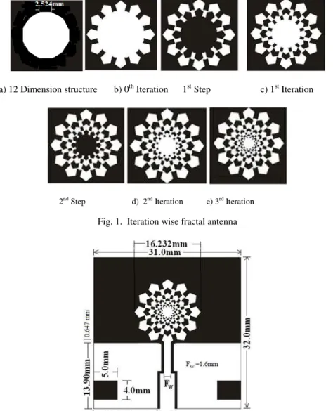
a) 12 Dimension structure b) 0th Iteration 1st Step c) 1st Iteration
2nd Step d) 2nd Iteration e) 3rd Iteration
Fig. 1. Iteration wise fractal antenna
Fig. 2. Proposed tree- type fractal Antenna
III. EFFECT OF DESIGN PARAMETERS
Brazilian Microwave and Optoelectronics Society-SBMO received 9 Aug. 2011; for review 18 Aug. 2011; accepted 19 April 2012
Brazilian Society of Electromagnetism-SBMag © 2012 SBMO/SBMag ISSN 2179-1074 Fig. 3. Current distribution at 6 GHz
A. Effect of each iteration
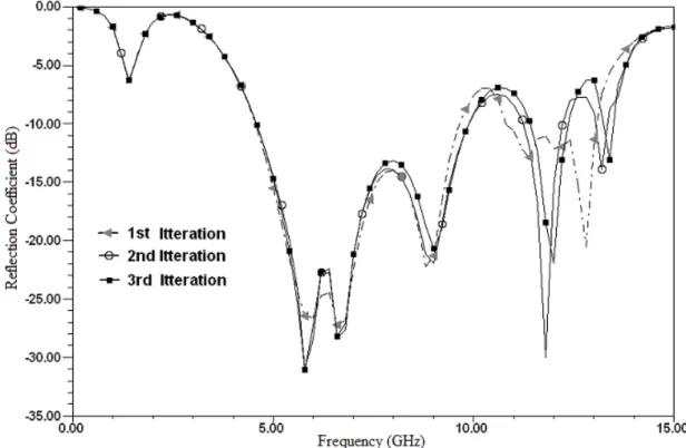
The proposed tree-type fractal antenna has been simulated using HFSS10 with respect to each iteration. The simulated results are shown in Fig. 4. It is clear from the simulated results as the iteration increases, there is little variation in first resonant frequency to lower frequency side as well as improvement in reflection coefficient at the lower and higher frequency side. This improves overall impedance bandwidth of antenna to some extent. In this, third iterative antenna is fabricated with optimized dimension to validate with simulated result.
Fig. 4. Simulated results of each iteration of antenna
Brazilian Microwave and Optoelectronics Society-SBMO received 9 Aug. 2011; for review 18 Aug. 2011; accepted 19 April 2012
Brazilian Society of Electromagnetism-SBMag © 2012 SBMO/SBMag ISSN 2179-1074 The proposed tree–type antenna is simulated for gap between feed width and ground. This gap is important for input matching to the radiating element. The proposed antenna has been simulated for various value of the gap between feed and ground with the step of 0.1 mm from 0.275 mm to 0.575
mm. The simulated results are shown in Fig. 5. The effect of the gap is clearly visible in the simulated results. The optimum value of gap has been achieved 0.475 mm. The feed width has been optimized in two step i.e near coaxial connector W=3.0mm and near the patch FW = 1.6 mm. Initially value of feed width and gap for optimization have been taken W=3.2 mm and G=0.275 mm. For this optimized G=0.475 mm, W=3.0 mm, Fw = 1.6 mm and fixing other parameters, the reflection coefficient is achieved better than -10 dB throughout band.
Fig. 5. Simulated results of various gap between feed and ground
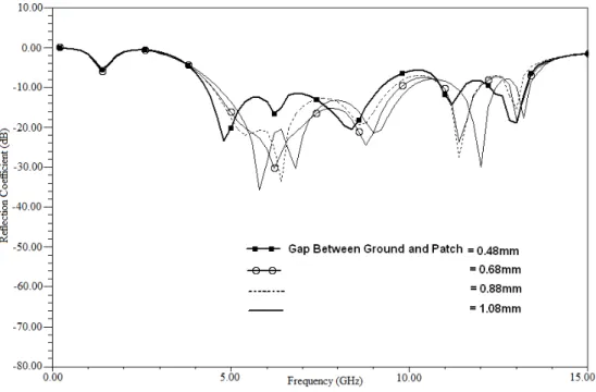
C. Effect of Gap between patch and ground
Brazilian Microwave and Optoelectronics Society-SBMO received 9 Aug. 2011; for review 18 Aug. 2011; accepted 19 April 2012
Brazilian Society of Electromagnetism-SBMag © 2012 SBMO/SBMag ISSN 2179-1074
Fig. 6. Simulated results of various gap between ground and patch
D. Effect of the Ground Plane Length
Brazilian Microwave and Optoelectronics Society-SBMO received 9 Aug. 2011; for review 18 Aug. 2011; accepted 19 April 2012
Brazilian Society of Electromagnetism-SBMag © 2012 SBMO/SBMag ISSN 2179-1074
Fig. 7. Simulated results of various ground length
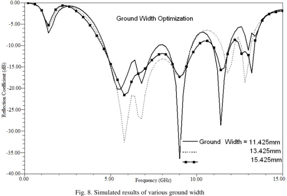
E. Effect of the Ground Plane Width
Brazilian Microwave and Optoelectronics Society-SBMO received 9 Aug. 2011; for review 18 Aug. 2011; accepted 19 April 2012
Brazilian Society of Electromagnetism-SBMag © 2012 SBMO/SBMag ISSN 2179-1074
Fig. 8. Simulated results of various ground width
IV. EXPERIMENTAL RESULTS AND DISCUSSION
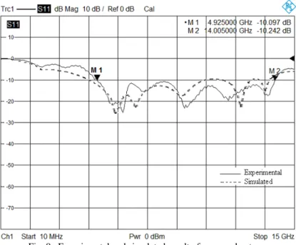
The proposed fractal antenna has been fabricated with optimized dimension as shown in Fig. 2. The antenna has been tested using R & S VNA ZVA40. The experimental result of proposed antenna exhibits the excellent UWB characteristics from 4.9 GHz to 14.0 GHz at VSWR 2:1. It corresponds to 96.296 % impedance bandwidth. The antenna is simulated using EM simulator HFSS with optimized dimension. The experimental and simulated results are in close agreement as shown in Fig. 9. The experimental result slightly varies from the simulated result. This may be due to the tolerance in manufacturing, uncertainty of the thickness and the dielectric constant and lower quality of SMA connector (VSWR = 1.3). The differences between simulated and experimental values may also be caused due to the soldering effects of an SMA connector, which have been neglected in our simulations. The SMA connector is not taken into account in all of the simulations so as to ease the computational requirements. It is noticed that this SMA port mainly affects the higher order resonances by shifting their resonant frequencies.
The peak gain of this proposed antenna has also been simulated and shown in Fig. 10. The peak gain of this antenna increases as the frequency increase. This is because the effective area of the antenna increases at the higher frequency because of shorter wavelength at high frequency. Beyond
Brazilian Microwave and Optoelectronics Society-SBMO received 9 Aug. 2011; for review 18 Aug. 2011; accepted 19 April 2012
Brazilian Society of Electromagnetism-SBMag © 2012 SBMO/SBMag ISSN 2179-1074
Fig. 9. Experimental and simulated result of proposed antenna
Fig. 10. Simulated peak gain of proposed antenna with respect to its iteration
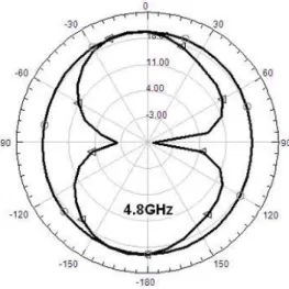
V. RADIATION PATTERNS
Brazilian Microwave and Optoelectronics Society-SBMO received 9 Aug. 2011; for review 18 Aug. 2011; accepted 19 April 2012
Brazilian Society of Electromagnetism-SBMag © 2012 SBMO/SBMag ISSN 2179-1074
Fig. 11. Simulated E and H-plane radiation pattern of proposed antenna at 4.8 GHz
Fig. 12. Simulated E and H-plane radiation pattern of proposed antenna at 6.0 GHz
Fig. 13. Simulated E and H-plane radiation pattern of proposed antenna at 8 GHz
Brazilian Microwave and Optoelectronics Society-SBMO received 9 Aug. 2011; for review 18 Aug. 2011; accepted 19 April 2012
Brazilian Society of Electromagnetism-SBMag © 2012 SBMO/SBMag ISSN 2179-1074 The studies of group delay and phase variation are important parameters for UWB system. The group delay has been measured by putting two identical antennas face to face at 30 cm distance in far field region. The experimental group delay versus frequency is shown in Fig. 14. The group delay is less than 1.5 ns in the operating frequency band with two identical antennas. Actually, it will be half of the calculated group delay using two antennas i.e 0.75 ns. It is observed that group delay is almost
constant throughout the band. It means variation in the phase is negligible. This indicates the phase linearity. This phase linearity of antenna is important in UWB system to transmit/receive the high data rate pulse without distortion.
Fig. 14. Experimental group delay of proposed antenna by using two identical antennas at 30 cm
VII. BACKSCATTERING OF PROPOSED ANTENNA
Brazilian Microwave and Optoelectronics Society-SBMO received 9 Aug. 2011; for review 18 Aug. 2011; accepted 19 April 2012
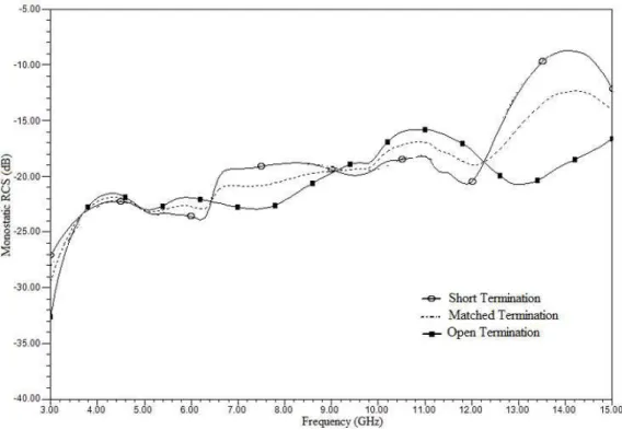
Brazilian Society of Electromagnetism-SBMag © 2012 SBMO/SBMag ISSN 2179-1074 Fig. 15. Simulated results of short, open and matched load termination
The total RCS (σ) of an antenna are divided into two part i.e. RCS of structural mode (σs) and antenna mode (σa). They are related to each other by where Φ is the phase difference between these two modes [13]. The antenna scattering can be calculated for the proposed antenna by using the model proposed in [14]. The antenna scattering for antenna mode and scattering mode can be calculated using following expression
(1)
Where, σ = total RCS of Antenna
= RCS of Structural Mode
= RCS of Antenna Mode
For Open Circuit termination,
(2)
For Short Circuit termination,
(3)
Brazilian Microwave and Optoelectronics Society-SBMO received 9 Aug. 2011; for review 18 Aug. 2011; accepted 19 April 2012
Brazilian Society of Electromagnetism-SBMag © 2012 SBMO/SBMag ISSN 2179-1074
(4)
For antenna mode scattering
(5)
In conclusion, the RCS of Structural Mode is the RCS of matched load termination and can also be calculated from equation (4). It is verified from equation (4) and matched load termination. The antenna mode scattering can be calculated from equation (5) using the RCS of open and short Circuit termination. The monostatic RCS with open and short termination is calculated using HFSS. The calculated monostatic RCS for each iteration is shown in Fig. 16. It is observed the monostatic RCS of proposed antenna (3rd iterative antenna) is greatly reduces above 13 GHz. This reduction of RCS is justified from experimental reflection coefficient which becomes poor above 13 GHz. The monostatic RCS is also calculated with respect to aspect angle. The antenna mode scattering RCS with respect to aspect angle can be calculated from monostatic RCS with short and open circuit termination as shown in Fig. 17 at 5 GHz. It is observed monostatic RCS for antenna mode scattering versus aspect angle varies as aspect angle vary.
Brazilian Microwave and Optoelectronics Society-SBMO received 9 Aug. 2011; for review 18 Aug. 2011; accepted 19 April 2012
Brazilian Society of Electromagnetism-SBMag © 2012 SBMO/SBMag ISSN 2179-1074 Fig. 17. Simulated results with short, open and matched termination versus aspect angle
VIII. CONCLUSIONS
The proposed tree–type fractal antenna has designed and implemented experimentally. The antenna exhibits 96.297% impedance bandwidth. To achieve UWB characteristics from 5.825 GHz - 10.6 GHz for DS-CDMA system, the effects of various design parameters have been studied thoroughly. The simulated results are found in good agreement with experimental results. The radiation pattern of the antenna is omni-directional in H-plane and bidirectional in E-plane. The group delay of this antenna is less than 0.75 ns. The phase variation is almost negligible throughout the band. The backscattering of this antenna is good through the operating band. This makes the antenna strong candidate for secure and military applications. This antenna is simple to fabrication, compact in size, easy to integrate with the device and MIC/MMIC circuits. Such type of antenna is useful for UWB DS-CDMA system, microwave imaging and vehicular radar.
ACKNOWLEDGEMENT
Authors are grateful to the Vice Chancellor, Pro-Vice Chancellor, Dean (Acd) of Defence Institute of Advanced Technology (Deemed University), Pune, India for permitting to publish this work. Author is also thankful to the colleague of the Department of Electronics Egg. for timely support and cooperation.
REFERENCES
[1] G. Breed, “A summary of FCC rules for UWB communications,” High Frequency Electronics, pp. 42–44, Jan. 2005.
Brazilian Microwave and Optoelectronics Society-SBMO received 9 Aug. 2011; for review 18 Aug. 2011; accepted 19 April 2012
Brazilian Society of Electromagnetism-SBMag © 2012 SBMO/SBMag ISSN 2179-1074
[3] International Telecommunication Union, Radio communication Study Groups, “Framework for the introduction of devices using ultra-wideband technology,” Document 1/85(Rev.1)-E, 09, Nov. 2005.
[4] Kamya Yekeh Yezdandoost and Ryuji Khono "UWB antenna,” IEEE radio communication , pp. 529-532, Jun. 2004.
[5] D. H. Werner and S. Ganguly, “An Overview of Fractal Antenna Engineering Research,” IEEE, Antenna and Propagation Magazine, Vol. 45, No. 1,38-57,2003.
[6] N.Cohen, “Fractal Antenna Applications in Wireless Telecomm.,” Proceeding Professional Program Elect. Industry Forum pp. 43-49, 1997.
[7] M. R. Haji-Hashemi, M. Mir-Mohammad Sadeghi, and V. M. Moghtadai,”Space-filling patch antennas with CPW –feed,” Progress in Electromagnetic Research Symposium, March 26-29, 2009.
[8] Edward Lule, Tadeusz Babij, and Time Derivative, “Koch Island Fractal Ultra Wideband Dipole Antenna,” IEEE Antennas and Propagation Society International Symposium, Vol.3, 20-25, June 2004, pp. 2516 – 2519.
[9] Raj Kumar et. al.,”On the design of inscribed triangle non-concentric circular fractal antenna,”, MOTL, Vol.52, No. 12, Dec. 2010.
[10] Raj Kumar et. al.,”Design of CPW-fed fourth iterative UWB fractal antenna,” International Journal of Microwave and optical Technology, Vol.6, No. 5, pp. 320-327, Nov 2010.
[11] E. F. Knott, et. al., “Radar Cross Section,” 2nd edition, SciTech, Raleigh, NC, 2004.
[12] D. Pozar, “Radiation and scattering from a microstrip patch on a uniaxial substrate," IEEE Trans. Antennas Propag., Vol. 35,No. 6, pp. 613-621, 1987.
[13] Y. Liu and S. X. Gong, “A novel UWB clover-disc monopole antenna with RCS reduction," Journal of Electromagnetic Waves and Applications, Vol. 22, No. 8-9, pp. 1115-1121, 2008.