Dual Band U- shaped microstrip antenna for
wireless Communication
1
Vinod K. Singh, 2 Zakir Ali
ABSTRACTThis paper presents novel coaxial feed, microstrip antenna with wide bandwidth. This U-shaped microstrip antenna offers a dual band. Low profile, light weight, easily mounted and broad bandwidth are the principle characteristics for antenna designed for wireless applications. The microstrip antenna is suitable for wireless applications except for its narrow band width. This paper suggests an alternative approach in enhancing the band width of microstrip antenna for the wireless application operating at a frequency of 2.5 GHz. A bandwidth enhancement of more than 7% was achieved. The measured results have been compared with the simulated results using software IE3D version-9.0.
Keywords-Rectangular, U- shaped microstrip antenna
I. INTRODUCTION
Microstrip patch antennas (MPAs) have attracted widespread interest due to their small size, light weight, low profile and low cost as well as to the fact that they are simple to manufacture, suited to planar and non planar surfaces, mechanically robust, easily integrated with circuits, allow multi frequency operation to be achieved [1] Linearly polarized microstrip antennas (LPMAs) are widely used in many wireless communication applications. The classification of the LPMAs is based upon the single-feed or dual-feed types. Single-feed wideband LPMAs are currently receiving much attention. Recently in [2], another design was proposed. In this design, LP operation was accomplished by using the U-slot of unequal lengths for a square microstrip antenna using a coaxial feed. The symmetrical U-slot cut microstrip antenna structure can generate two orthogonal modes for LP radiation; therefore no extra stubs, notches or chamfering at corners of the rectangular patch are necessary. The patch radiator was fabricated from the copper sheet and mounted on a duroid substrate. However, the patch radiator on the duroid substrate is mechanically unstable. Moreover, the coaxial feed in this antenna makes it unsuitable for a low-cost antenna array design. A LPMA with combining slots and patch has been proposed for dual-band operation [3]. They had used a power divider to excite the four slots for LP operation. In this paper, we propose a new compact, coaxial feed, linear polarized, C-shaped microstrip antenna. The antenna consists of a C-shaped patch radiator and a coaxial feeding structure. By cutting a slot in the patch radiator, the excited surface current of the fundamental TM10 mode
on the patch is significantly lengthened to make the fundamental resonance frequency lower. The C-shaped dimensions are optimized to radiate wide linearly polarized waves. The results are compared with the results obtained by EM simulator software, IE3D.
II. ANALYSISOFPROPOSEDANTENNA
[5], a normal microstrip patch antenna can be modeled as parallel RLC circuit. The current flows from the feeding point to the top and bottom edges of the patch. Values of L and C are determined by the currents path length:
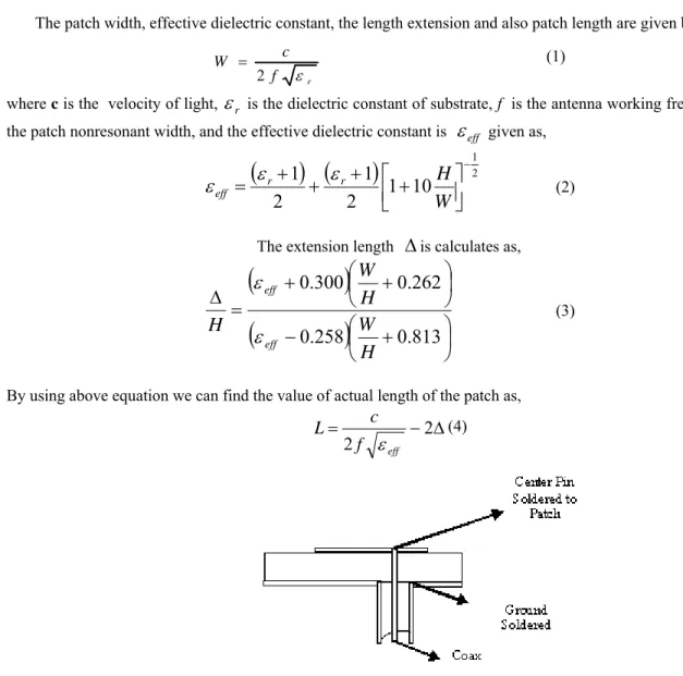
The patch width, effective dielectric constant, the length extension and also patch length are given by
r
f c W
2
(1)
where cis the velocity of light,
r is the dielectric constant of substrate, f is the antenna working frequency, W is the patch nonresonant width, and the effective dielectric constant is
eff given as,
21
10
1
2
1
2
1
W
H
r r
eff
(2)The extension length
is calculates as,
813
.
0
258
.
0
262
.
0
300
.
0
H
W
H
W
H
eff eff
(3)
By using above equation we can find the value of actual length of the patch as,
2
2f eff c L
(4)Figure 1. Side view of rectangular microstrip antenna
III. OPTIMIZING THE DUAL-BAND ANTENNA FOR A WIDE BANDWIDTH
The cross-section of the proposed coaxial feed, linearly polarized-U shaped microstrip antenna is shown in “Fig. 2”. W is the width and L is the length and h is the thickness of rectangular microstrip patch antenna. The rectangular Microstrip patch with a U-shaped has a side length ls and width of the proposed antenna. The co-axial
feed is located at the corner of the U-shaped rectangular microstrip antenna. A parametric analysis is conducted to optimize the proposed antenna for good LP operation. Now we have taken small value of substrate thickness is 1.6 mm at 2.5 GHz operating frequency of proposed antenna. From the cavity model explained above, the electric field is assumed to act entirely in the z-direction and to be a function only of the x and y coordinates i.e. [6-7]
x
y
Ez
Z
E
ˆ
,
(5)0
2 2 2 2 2
Z Z ZK
y
(6)
The outward current flowing on the perimeter of the patch must be zero (since the patch boundary is an open-circuit). So
0
Z (7)Where n is the outward normal vector at the perimeter of the patch by using the separation of variables, the electric field of the m and n mode number is
L
y
n
W
m
Cos
Z
0 (8)
In order to calculate the far field, the aperture model is used. By using Green's function the following general form of the far field for any (m, n) mode
cos
sin
sin
cos
cos
cos
2
x y x yjkr
i
i
r
jke
r
(9) Where
2
cos
1
1
2
sin
1
1
mj
W
mW
x
2
2
sin
1
2
2
sin
sin
2
0
a
j
c
L
n
c
L
n
c
L
h
n nand
2
cos
1
1
2
sin
1
1
nj
L
nL
y
2
2
sin
1
2
2
sin
sin
2
0
a
j
c
W
m
c
W
m
c
W
h
m mThen the far field components are
cos
sin
2
x yjkr
r
jke
(10)
sin
cos
cos
cos
2
x yjkr
r
jke
(11) Where
KSin
Cos
0
2
K
and
0= wavelength in free space.Equation (9) enables one to plot the radiation pattern for every mode of the rectangular microstrip patch antenna
Figure 2. Geometry of U-shaped rectangular microstrip antenna
IV DISCUSSIONANDRESULTS
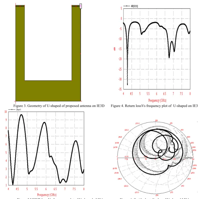
Based on the results from the simulations and measurements, it is clear that the single layer microstrip antenna has a very narrow bandwidth. There is a requirement to use a bandwidth enhancement technique in this microstrip antenna and the slot loaded technique is deployed [16]. Using this technique, both the simulated and measured results give a bandwidth enhancement at more than 7%. There is a very good agreement between the simulated and measured results. The U-shaped microstrip patch antenna designed on EM simulator software IE3D and after simulation reflection coefficient S11 is obtained. It is mounted on a RT duroid substrate of dielectric constant 4.2. We have
operating frequency at 2.5 GHz.
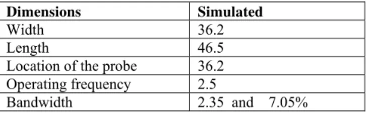
Table 1: Simulated and measured results U-shaped microstrip antenna Dimensions Simulated Width 36.2 Length 46.5 Location of the probe 36.2
Operating frequency 2.5
Bandwidth 2.35 and 7.05%
Figure 3. Geometry of U-shaped of proposed antenna on IE3D Figure 4. Return lossVs frequency plot of U-shaped on IE3D.
Figure 5.VSWR loss Vs frequency plot of U-shaped MSA Figure 6. Smith chart display of U-shaped MSA
V CONCLUSIONS
The technique for enhancing bandwidth of the Microstrip antenna has been shown and it can be used for various wireless applications . As mentioned, this technique has its advantages such as it does not increase the lateral size of the microstrip antenna and disadvantages such as it increases the height of the microstrip antenna. Therefore, trade-of issues need to be considered in this design. Simulations and measurements on the new proposed antenna configuration have provided a useful design for a wide bandwidth.
REFRENCES:
[1] Thomas A. Milligan “2ndaddition Modern antenna design”pp: 318-354.
[2] TONG K.F., WONG T.P.: ‘Circularly polarized U-slot antenna’, IEEE Trans. Antennas Propag., 2007, 55, (8), pp. 2382–2385.
[3] TANAKA T., HOUZEN T., TAKAHASHI ITO K.: ‘Circularly polarized printed antenna combining slots and patch’, IEICE Trans. Commun., 2007, E90-B, (3), pp. 621–628.
[6] Nasimuddin Z.N. Chen “Aperture coupled asymmetrical c-shaped slot microstrip antenna for circular polarization”, IET Microw Antennas Propag. , Vol. 3, Iss. 3, pp. 372–378, 2009.
[7] Shivnarayan & Babu R Vishvakarma “Analysis of notch-loaded patch for dual-band operation”, Indian Journal of Radio & Space Physics. Vol.35, pp.435-442.
[8] Mohammad A. A. Subhi H. Ahmad A. K. and Juma S. M. “Cavity model analysis of rectangular microstrip antenna operating in TM03 mode”, IEEE proc. pp. 0-2218-2223, 2006.
[9] S. K Satpathy, Vijay Srinivasan, K P Ray and G Kumar, “Compact microstrip antennas for personal mobile communication”, IEEE proc. pp. 245-248, 1998.
[10] Wong B. F. & Lo Y. T., “Microstrip antenna for dual frequency operations”, IEEE Trans. Antenna Propag.1984.
[11] Pandey V. K. & Vishvakarma B R, “Theoretical analysis of linear array antenna of stacked patches, indian j radio & space physics”, 2005. [12] K. R. Carver and J. W. Mink, “Microstrip antenna technology”, IEEE Trans. Antenna Propag. Vol. AP- 29, pp.1-24, 1981.
[13] J. R. James and P. S. Hall, "Handbook of microstrip antennas," Peter Peregrinus Ltd, London, 1989.
[14] E. F. Bolinder, “Geometrical analysis of partially polarized electromagnetic waves,” IEEE Trans. Antennas Propag., Vol. AP-15, No. 1, pp. 37–40, January 1967.
[15] G. A. Deschamps, “Microstrip microwave antennas,” Presented at the Third USAF Symposium on Antennas, 1953.
[16] RSA Raja Abdullah, D. Yoharaaj, and Alyani Ismail “Bandwidth Enhancement Technique in microstrip antenna for wireless application”, PIERS ONLINE, VOL. 2, NO. 6, pp.633-639, 2006.