On the Design of UWB Circular Fractal
Antenna with Notched-Band Characteristics
Using W-shape Slot
Raj Kumar, Prem Narayan Chaubey1 and I. Srikant2
Microwave and Millimetre wave Antenna Lab. 1,2
M. Tech., Student of DIAT
DIAT (Deemed University), Girinagar, Pune-411025 Email: [email protected]
Abstract - This paper presents the design of notched-band
antenna with CPW - feed. The notched – band has been achieved by using the W-shape slot in ground plane. The antenna has been simulated using a 3D – Electromagnetic simulator. The experimental results of proposed antenna exhibit ultra wideband characteristics from 2.0 - 15.0 GHz except the notched-band frequency from 5.0 – 6.0 GHz. The slot is optimized with respect to width, length and position for a detailed study of notched-band characteristics. It is observed that the centre frequency and bandwidth of notched-band depend on the length and width of slot respectively. The experimental radiation patterns of this antenna are omni-directional in H-plane and biomni-directional in E-plane. This antenna can be useful for UWB system, medical imaging and vehicular radar.
Index Terms- Monopole antenna, Fractal Geometry, UWB antenna,
Notch-band, CPW – feed and UWB system
I. INTRODUCTION
With the release of the 3.1 – 10.6 GHz band for ultra-wideband (UWB) operation, a variety of
typical UWB applications evolved are indoor/outdoor communication systems, ground penetrating
and vehicular radars, wall and through-wall imaging, medical imaging and surveillance. Many future
modern UWB communication systems will be utilized to transmit /receive the high data rate with low
power consumption at short range communication [1-2]. Therefore, the realization of UWB antennas
in planar technologies with small size is the primary requirement. The antenna should have
omni-directional radiation patterns throughout the band. In UWB operating band, the WLAN signal is also
present which interferes the UWB signal. To stop the interference by external WLAN signal (5.0 to
6.0 GHz), a band notched filter is required
.
Using a band notched filter separately along with antennaincreases the system size as well as system complexity. To overcome this complexity, many
researchers have reported antennas with notched-band characteristics using various shapes of slots in
ground plane, feed line and on the radiating patch [3-10]. The most common technique in open
literature is a slot loading in the radiation patch [3–5]. This gives poor cross-polarization
include incorporating a L-shaped slits in the ground plane to achieve notched-band function [6-8].
Beside these methods, another method is to design a resonant circuit on the feed line [9, 10]. The
L-shape slot reported in [6-8] is large in size. There is a need to have a compact slot in size. This paper
reports the compact W-shape slot in ground to achieve the notched-band characteristic.
Several researchers have also reported the UWB characteristics of antenna using fractal geometry.
Fractal geometry is useful for size reduction and good impedance matching throughout the band.
Some researchers have reported the UWB fractal antenna with CPW - feed [10-13]. Fractal geometry
in monopole antennas with CPW - feed offers the advantages of compactness, UWB characteristics
throughout the band, good radiation pattern and low dispersion.
In this article, a new UWB fractal antenna with notched-band characteristics is presented. The
notched-band characteristic is achieved by cutting a W-shape slot in ground plane. This antenna is
simple, easy to fabricate and integrate with MIC/MMICs devices. The notched-band characteristic is
experimentally validated and simulated with respect to various parameters of the slot in the ground
plane.
This paper has been divided into six sections. In Section – I, the introductory part of article is
discussed. The second section of the paper describes the antenna geometry and slot in ground plane
responsible for notched-band characteristics. In Section – III, the approximate design expressions for
notched-band frequency is given. The Section – IV concentrates on the parametric analysis of slot
dimensions responsible for notched-band characteristics. The section – V discusses the experimental
and simulated results of antenna with and without notched-band and in last section the conclusions of
the article is given.
II. ANTENNA GEOMETRY
The monopole antenna with CPW - feed is convenient to integrate with MIC/MMICs circuits. The
fractal antenna with CPW – feed is advantageous to achieve the UWB characteristic without any
additional matching circuitry. This paper proposes a new fractal antenna to achieve UWB
characteristics. The geometry of proposed fractal antenna has been constructed inside the circular disc
of 30 mm diameter with metallization thickness of 0.1 mm with the centre as origin (0,0). This is
called zeroth iteration. The 1st iterative structure has been constructed by creating 10 different
triangles. First triangle with side length of 16.63 mm is made inside the circular disc. This triangle is
moved along coordinate (-4.5 mm, 2.76 mm). The second triangle of side length 18.72 mm is made
and rotated by an angle 400. This triangle is moved along (-3.5 mm, -2.1 mm) coordinate. The third
triangle with side length of 16.64 mm is rotated by 650 and moved along (-0.7 mm, -6.2 mm)
coordinate. The fourth triangle with side length of 18.02 mm is rotated by 900 and moved along (3.3
moved along (5.79 mm, 8.75 mm) coordinate. The sixth triangle with side length of 16.64 mm is
rotated by an angle 900 and moved along (-0.7 mm, 5.7 mm) coordinate. The seventh triangle with
side length of 18.02 mm is rotated by an angle 1100 and moved along (3.7 mm, -5.2 mm) coordinated.
The eighth triangle with side length of 10.1 mm is rotated by an angle 1060 and moved along (6.15
mm, -8.4 mm) coordinate. Similarly, ninth & tenth triangles each of side length of 7.348 mm are
rotated by an angle 1000 and are moved along (9.15 mm, -7.75 mm) and (9 mm, 7.8mm) coordinate
respectively. After placing these triangles, the geometry is obtained as shown in Figure 1 (a). Then
these triangles are united and subtracted from the circular disc of 30 mm diameter. Now, one more
circular disc with diameter of 23.4 mm and metallization thickness of 0.1 mm is made with centre at
-3.3 mm as shown in Figure 1(b). Then this circular disc is subtracted as shown in Figure 1(c). This
geometry is fed by CPW - feed. This is called 1st iteration as shown in Figure 1(d).
In 2nd iteration, geometry of 1st iterative structure is scaled down by a factor of 0.79, copied in a
circle of 23.4 mm diameter with centre at (0,-3.3mm) and subtracted. We get the geometry similar to
first iterative geometry but smaller in size. This geometry is made to intersect with the original circle
near the feed line. This is called second iteration. In 3rd iteration, the second iterative fractal geometry
is copied and scaled down with factor of 0.8. This geometry is copied in the circle of 18.72 mm
diameter with centre (0, -5.64mm). This copied geometry is made to intersect at the original circle
near feed line. In 4th iteration, the third iterative fractal geometry is copied and scaled down by factor
of 0.495. This geometry is copied in circle of 9.2664 mm with centre at (0, -10.3668 mm) and
subtracted from circular disc. This geometry is made to intersect with the original circle near feed line
in similar manner as earlier. This is the final proposed fractal antenna with optimized dimensions as
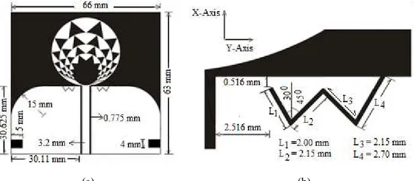
shown in Figure 2a.
The W-shape slot is created in the ground plane on both sides of the feed line as shown in Figure
2a. The dimensions of the W-shape slot are shown in Figure 2b separately to have the clarity in
dimensional. The W-shape slot is made 2.516 mm away from ground edge at feed side. The total
angle of the W-shape slot has been taken as 75 degree. One side of the W-shape slot cuts the upper
edge of ground plane. Another side of W-shape slot is at 0.516 mm below the upper edge of ground
plane. The total length of the slot cut in ground plane is 9.0 mm.
(a) (b)
Fig. 2 a) Proposed fractal antenna with optimized dimensions, b) Slot dimensions
III. DESIGN EXPRESSIONS
The notched – band has been created by cutting the slots in the ground plane. A W- shape slot is chosen to
be the slot cut on both sides of the ground plane with its dimensions optimized systematically on HFSS
simulation software. The optimized dimensions are slot width w = 0.21 mm and length of the slot L = 9.0
mm. These dimensions provide exact notched-band characteristics from 5.0 GHz to 6.0 GHz. The
formulation for the calculation of notched-band centre frequency (fnotch) can be as follows:
(1)
Where = phase velocity
εr = relative permittivity of the substrate b = thickness of the substrate
w = width of the notch
εeff = effective permittivity of the substrate
The total length of the slot is equal to Lnotch=L1+L2+L3+L4 , where L1=2.0 mm, L2 =2.15 mm,
L3=2.15 mm and L4=2.70 mm. Therefore, total length is L=9.0 mm. Since the slot is cut through the
ground at upper edge at one end and other end in the ground plane. We consider it is to be open
circuited at one end and short circuited at the other. The resultant length of slot is equal to λ/4 at
notched center frequency. So, length of the slot i.e. Lnotch = λ/4. This can be substituted in equation
(1);
This expression can be used for calculating the rough slot length of slot in ground plane. This
estimated length is optimized using 3D - Electromagnetic software. This antenna with notched-band
characteristic has been designed on FR4 substrate of dielectric constant r = 4.3 and thickness of
substrate h = 1.53 mm.
IV. PARAMETRIC STUDY OF SLOT
The parametric study of slot in ground for creating the notched-band characteristic has been carried
out using HFSS software. The W-shape slot width, length and its position are the critical parameters
to achieve the required notched - band characteristics. This is because, current distribution is stronger
at notched-band centre frequency 5.5 GHz. The current distribution on the W-shape slot antenna is
shown at frequencies 3.5 GHz and 5.5 GHz in Figure 3. It is seen that the current density is stronger
around slot at frequency 5.5 GHz i.e. at band-notched centre frequency. The current density is
negligible at other than the notched - band frequency i.e. at 3.5 GHz as shown in Figure 3. Due to
stronger current density at frequency 5.5 GHz around W-shape slot, the W- shape slot length, width
and position affect the notched - band characteristics. The proposed antenna has been optimized for
the notched - band from 5.0 – 6.0 GHz. The proposed antenna with optimized dimension is shown in
Figure 2.
Fig. 3. Current distribution on proposed antenna at 3.5 GHz and 5.5 GHz
A. Effect of W - Shape Slot Length
The proposed antenna has been simulated with respect to various lengths of W - shape slot. The
total length of slot L is varied with a step of 0.5 mm. The simulated results of various slot length are
shown in Figure 4. It is observed from the simulated results as the total length of the slot increases the
length of W - shape slot increases, the band width of notched - band remains unaffected. The centre
frequency of notched-band is observed at 5.6 GHz for 9.0 mm slot length, 5.3 GHz for 9.5 mm slot
length, 5.1 GHz for 10.0 mm slot length, and 4.5 GHz for 11.0 mm slot length respectively.
Fig. 4. Simulated results of proposed antenna with respect to various length of slot
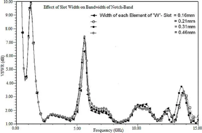
B. Effect of W - Shape Slot Width
The proposed antenna has also been simulated with respect to various width of the W – shape slot.
The length of the slot L = 9.0 mm and other optimized parameters are kept constant. The simulated
results of various values of slot width i.e. 0.16 mm, 0.21 mm, 0.31 mm and 0.46 mm are shown in
Figure 5. It is observed for the narrow slot width, that the notched-band bandwidth is narrow. As the
slot width increases, the notched bandwidth also increases. It is because the wide slot offers a low
impedance and narrow slot offers the high impedance at notched-band frequency. The simulated
notched-band bandwidth at VSWR 2 for 0.16 mm, 0.21 mm, 0.31 mm, 0.46 mm slots width is around
Fig. 5. Simulated results of proposed antenna with respect to various width of slot
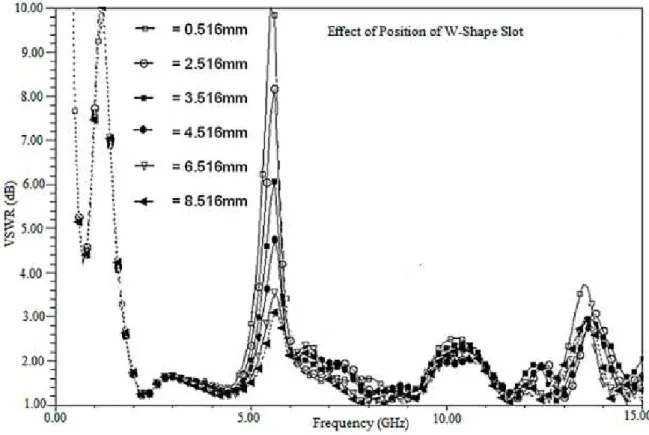
C. Effect of Position of Slot
The proposed antenna is also been simulated for various positions of slot. The original position of
the slot is 2.516 mm from ground edge at feed side. The proposed antenna has been simulated for the
position of slot i.e. 0.516 mm, 2.516 mm, 3.516 mm, 4.516 mm 6.516 mm and 8.516 mm away from
feed side with respect to its original position. As the position of the W – shape slot is shifted away
from the feed side, the VSWR at the notched-band reduces. This is because the current density
reduces around the slot as it is shifted away from feed side. The simulated VSWR with respect to
original position of slot 0.516 mm, 2.516 mm, 3.516 mm, 4.516 mm and 6.516 mm are 10.0345,
8.1526, 6.0679, 4.7352, 3.4131 and 3.0928 respectively. These simulated results are shown in Figure
6. It is also observed, as the W-shape slot is shifted away from the feed side, the notched bandwidth
also decreases. The simulated notched-band bandwidth is observed around 1.25 GHz for 0.516 mm
slot position, 1.05 GHz for 2.516 mm slot position, 0.95 GHz for 3.516 mm slot position, 0.85 GHz
for 4.516 mm slot position, 0.7 GHz for 6.516 mm slot position, and 0.6 GHz for 8.516 mm slot
Fig. 6. Simulated results of proposed antenna with respect to various position of slot
V. EXPERIMENTAL RESULTS AND DISCUSSION
The proposed fractal antenna has been fabricated with and without W - shape slot with optimized
dimensions. The W - shape slot in ground plane is optimized to create the notched-band with
dimensions 9.0 mm slot length, 0.21 mm slot width and 2.516 mm slot position from feed side. The
VSWR is improved without notched-band by optimizing the curvature of ground plane with 15 mm
radius and by putting two slot of 4 mm x 5 mm in ground plane at both side. The other optimized
dimensions are feed width 3.2 mm, gap between ground and feed 0.775 mm, gap between patch and
ground 0.5 mm. The both fractal antennas with and without notched-band are fabricated and tested
using R & S ZVA40 vector network analyzer. The experimental results acquired from vector network
analyzer exhibit the UWB characteristics. The measured results of the proposed antennas with and
without notched-band are compared as shown in Figure 7. It is observed that antenna offers the UWB
characteristic from 2.0 GHz to 15.0 GHz except the notched-band frequency 5.0 to 6.0 GHz. This
Fig. 7. Experimental VSWR of Proposed fractal antenna with and without notch
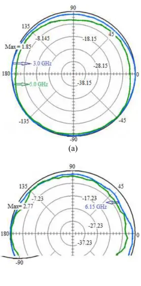
The radiation patterns of proposed antenna have been measured in the anechoic chamber at
selective frequencies. The H-plane radiation patterns of this UWB antenna are measured at 3.0 GHz,
5.0 GHz, 6.15 GHz and 9.975 GHz as shown in Figure 8. Similarly, the E-plane radiation patterns of
this UWB fractal antenna are measured at 6.25 GHz and 8.175 GHz as shown in Figure 9. The nature
of the radiation patterns are omni-directional in H-plane and bidirectional in E-plane. It is also
observed, as the frequencyincreases, the radiation patterns slightly varies which may be due to edge
(a)
(b)
Fig. 8. Experimental H-plane radiation patterns measured at 3.0 GHz, 5.0 GHz, 6.15 GHz and 9.975 GHz
The gain and radiation efficiency of the proposed antenna have also been calculated and tabulated
in table 1. It is revealed from tabulated results that the gain and radiation efficiency drop drastically at
notched-band frequency. This indicates that external signal like WLAN will not interfere in the
operating band of this antenna. It is also observed at higher frequency that the radiation efficiency
reduces which may be because of loss tangent of FR4 substrate.
Table 1: Gain and Radiation Efficiency of the proposed antenna
Frequency (GHz) Gain (dB) Efficiency (%)
2.0 1.0 94
3.5 2.45 96
5.5 -5.5 71
7.0 4.05 95
9.0 4.8 94.5
VI. CONCLUSIONS
The new proposed fractal antenna has been designed and experimentally validated. The antenna
exhibits UWB characteristics beyond the FCC recommended band (3.1-10.6 GHz). The notched -
band from 5.0 GHz to 6.0 GHz is achieved using W-shape slot in ground plane. The effects on the
notched - band characteristic have been studied with respect to length, width and position of slot. The
length and width of slot affect the centre frequency and bandwidth of notched - band respectively.
Measured radiation pattern of the proposed antenna is omni-directional in H-plane and bidirectional in
E-plane. The gain and radiation efficiency of this antenna fall down drastically at notched-band centre
frequency. This antenna is conformal, lightweight, small in size, low cost and easy to integrate with
MIC/MMICs devices. Such type of antenna can be used for UWB system, Microwave medical
imaging, vehicular radar and precision positioning.
ACKNOWLEDGEMENT
Authors are grateful to the Vice Chancellor, Pro-Vice Chancellor, Dean (Acd) of Defence Institute
of Advanced Technology (Deemed University), Pune, India for permitting to publish this work.
Author is also thankful to the colleague of the Department of Electronics Engg. for timely support and
cooperation.
REFERENCES
[1] FCC, Federal Communication Revision of part 15 of the Commission’s Rules Regarding Ultra – Wideband Transmission System, FCC, First Report and order FCC, 02, V48, 2002.
[2] L. Yang and G. B. Giamalkis, “Ultra wide band Communications,” IEEE signal processing Magazine, Nov. 2004, pp. 26-28.
[3] X.-R. Yan, S.-S. Zhong, and G.-Y. Wang, “The band-notch function for a compact coplanar waveguide-fed super-wideband printed monopole,” Microwave Opt Technol. Lett. 49, 2007, 2769–2771.
[4] T. P. Vuong, A. Ghiotto, Y. Duroc, and S. Tedjini, “Design and characteristics of a small Uslotted planar for IR -UWB, “Microwave Opt Technol. Lett. 49 (2007), 1727–1731.
[6] S. Ho, J.-W. Baik, and Y.-S. Kim, “A coplanar fed monopole ultra-wideband antenna having band-notched frequency function by two folded-striplines,” Microwave and Optical Technology Lett. 49 (2007), 2747–2750.
[7] C.-Y.-D. Sim, W.-T. Chung, and C.-H. Lee, “An octagonal UWB monopole antenna with 5 GHz band-notch function,” Microwave and Optical Technology Lett. 51 (2009), 74–78.
[8] J.-B. Jiang, Y. Song, and Z.-H. Yan, “Band-notch UWB printed antenna with an inverted-L-slotted ground,” Microwave and Optical Technology Lett. 51 (2009), 260–263.
[9] Y. Ding, G. Wang, and J.-G. Liang, “Compact band-notched ultra wideband printed antenna,” Microwave and Optical Technology Lett. 49 (2007), 2686–2689.
[10] S.-W. Qu, J.-L. Li, and Q. Xue, “A band-notched ultra wide-band printed monopole antenna,” IEEE Antennas Wireless Propag. Lett. 5 (2006), pp. 495–498.
[11] Raj Kumar et.al. “On the design of inscribed triangle non-concentric circular fractal antenna,” Microwave and Optical Technology Letters, Vol.52, No. 12, Dec. 2010, 2696-2699.
[12] Raj Kumar et.al., “On the design of wheel shape Fractal antenna,” Microwave and Optical Technology Letters, Vol.53, No.1, pp.155-159, January 2011.