Stress analysis in oral obturator
prostheses over parallel and tilted
implants: photoelastic imaging
Aldiéris Alves Pesqueira
Marcelo Coelho Goiato
Daniela Micheline dos Santos
Adhara Smith Nobrega
Stress analysis in oral obturator prostheses over
parallel and tilted implants: photoelastic imaging
Aldiéris Alves Pesqueira,aMarcelo Coelho Goiato,bDaniela Micheline dos Santos,bAdhara Smith Nobrega,b Marcela Filié Haddad,bAgda Marobo Andreotti,band Amália Morenob
aUniversity Sagrado Coração, Department of Oral Biology, Faculty of Dentistry, Bauru, São Paulo, Brazil
bUniversidade Estadual Paulista, Araçatuba Dental School, Department of Dental Materials and Prosthodontics, Araçatuba, São Paulo, Brazil
Abstract. This study aimed to evaluate the stress distribution through the photoelastic method in implant-retained palatal obturators prostheses. Two photoelastic models with bucco-sinusal communication were fabricated, one model without implants and another with two parallel implants and one tilted in the molar region. A conventional obturator prosthesis and five implant-retained obturators dentures with different attachment systems were fabricated: OR, three individualized O-rings; BC, bar clip; BOC, implants splinted by bars associated with two O-rings positioned at the center of the bar; OD, implants splinted by bars associated with two O-rings positioned in distal cantilever; and BOD, implants splinted by bars with clips associated with two O-rings positioned in distal cantilever. Each assembly (model/attachment system/prosthesis) was positioned in a circular polariscope and a load of 100 N was applied on each implant. The results were obtained by observing the photographic record of the tensions in the photoelastic models resulting from the application of load. It can be observed that a larger amount of stress fringes on BC system. It was concluded that the attachment system has a direct influence on the stress distribution of implant-retained obturator prostheses, with the three individualized O-rings exhibiting the lowest stress values, and tilted implants presented a biomechanical behavior similar to parallel implants.©The Authors. Published by SPIE under a Creative Commons Attribution 3.0 Unported License. Distribution or reproduction of this work in whole or in part requires full attribution of the original publication, including its DOI.[DOI:10.1117/1.JBO.18.10.106009]
Keywords: dental implants; palatal obturators; maxillofacial prosthesis; dental prosthesis.
Paper 130559R received Aug. 5, 2013; revised manuscript received Sep. 16, 2013; accepted for publication Sep. 23, 2013; published online Oct. 15, 2013.
1 Introduction
The installation of implants with distal inclination in areas of greater bone density, as in the region of first molars, has been an alternative for atrophic ridges of maxilectomized patients to improve the geometrical arrangement of the assembly prosthe-sis/implant. Without this technique, these regions would receive shorter implants or would require bone graft, increasing the complexity, time and cost of the treatment.1–3
Allied to implants, different types of attachment systems are usually indicated for improving the retention and stability of overdentures,4–8such as ball systems, magnet, and bars, and
it is also possible to associate them with one another.4,5,7–11 The dental literature has shown many studies that approach the distribution of forces in order to collect better background information for planning of overdentures.4,5,7–9,12A
photoelas-ticity method through images has been widely applied in den-tistry and allows a direct observation of stress distribution on structures, based on the ability of certain transparent materials to display color standards named isochromatic fringes when they are loaded and observed through a polarized light.4,5,7,13
Thereby, this study aimed to evaluate the stress distribution through the photoelastic method in implant-retained palatal obturators over two parallel implants and one tilted using differ-ent attachmdiffer-ent systems and convdiffer-entional obturator (without
implants). Several studies4,5,7,14–19show that stress is absorbed
by the O-ring system female component, which usually has a rubber ring surrounded by a metal capsule, It can absorb or distribute more homogeneously the forces they are submitted to. So, this study’s hypothesis is that the system with three individualized O-rings will provide lower values of stress on the implants and supporting tissues, and that regardless of the attachment system, the greatest stress will occur in tilted implant.
2 Materials and Methods
An experimental maxillary model with oral-sinus-nasal commu-nication was used to reproduce two identical laboratorial models confectioned with type IV dental stone (Durone; Dentsply Ind Com Ltda, Petrópolis, Rio de Janeiro, Brazil). One of the laboratory models was duplicated with fluid silicon (Sapeca Artesanato, Bauru, São Paulo, Brazil) in order to obtain the negative impression of the laboratorial stone model. Through this impression, the photoelastic model I was obtained (without implants). Therefore, it was poured into the mold photoelastic resin PL-2 (Vishay Measurements Group Inc, Raleigh, North Carolina), manipulated and spatulated according to the manufacturer’s instructions. Subsequently, the assembly (moldþphotoelastic resin) was placed into the resin polymer-izer at a pressure of 40 pounds for the removal of internal bub-bles. After polymerization of the PL-2 resin, the model was separated carefully from the mold and subjected to finishing pol-ish, which was performed with fine granulation water sandpaper (600, 800, 1200, and 1500).4,5,7
For preparation of the photoelastic model II, three implants were positioned in the second laboratory model. Two of these were inserted parallel to each other in the region of incisor and canine using a parallelometer and the other in the region of the first molar was tilted 17 deg to the distal. To determine this incli-nation in the plaster model, a straight line was drawn with a slope of 17 deg to the distal region, with the assistance of a retro projector marker (Pilot Pen Brasil, São Paulo, Brasil), transparent adhesive paper (Plastific Comércio Plastificação Ltda, Belo Horizonte, Minas Gerais, Brasil), protractor, and ruler. In the vestibular region of the plaster model, this adhesive paper was glued in order to adequately guide the drilling of the plaster model in this region. After perforation, the implants analogues with3.75×13 mmand 4.1 mm platforms (Neodent, Curitiba, Paraná, Brasil) were inserted and fixed with Duralay acrylic resin (Duralay Reliance Dental MFG Co, Worth, Illinois), so that the analogue platform remains at the same level of the alveolar ridge.
The squared transfers (Neodent, Curitiba, Paraná, Brasil) were positioned and screwed to the analogs and were attached to each other with dental floss and Duralay acrylic resin. The obtaining of the stone model impression with transfers posi-tioned was performed according to the method described above for the obtainment of photoelastic model I.
After casting and polymerization of the silicon, the screws of squared transfer were removed to allow the removal of stone model, obtaining the silicone matrix with transfers already positioned. A titanium implant with external hexagon of3.75×
13 mm (Neodent, Curitiba, Paraná, Brasil) was adapted and screwed to this transferer and then the mold was filled with photoelastic resin PL-2, as previously described.
The photoelastic resin PL-2 laboratory models, with and without implants, were used to fabricate the obturator prosthe-sis. Five prostheses were fabricated. One mucous-supported obturator prosthesis (without implants) and four implant-retained obturator prosthesis using different attachment systems: OR, three individualized O-rings; BC, bar clip; BOC, implants splinted by bars associated with two O-rings positioned at the center of the bar; OD, implants splinted by bars associated with two O-rings positioned in distal cantilever; and BOD, implants splinted by bars with clips associated with two O-rings posi-tioned in distal cantilever.
The manufacture of obturators, application, and photoelastic analysis was carried out according to the study of Pesqueira et al.4Each assembly (prosthesis/photoelastic model with and
without an attachment system) was positioned in a circular polariscope into a glass with mineral oil. Thus, a load of 100 N at10 mm∕s was applied in the region of incisive, canine, and first molar on the opposite side of the communication. The load was unilateral to simulate a tendency of prosthesis’s inclina-tion.14,20Daas et al.14states that the prosthesis
’s working side moves down while its nonworking side moves up. Also, accord-ing to Barão et al.,20this greater movement requires the attach-ment system in a more critical way. Furthermore, the unilateral load is clinically relevant because it simulates the first phase of chewing, wherein the food stuff is placed in the prosthesis’s working side and no contact occurs in the nonworking side.
The images were recorded by a digital camera and trans-ferred to a computer, all models were qualitatively analyzed to verify the direction and intensity of stress based on other studies. In this sense, the higher the fringes order (N) and fringes
number are, the greater the stress intensity is. Additionally, the
closer the fringes are among each other, the higher the stress concentration is.
The analysis was divided according to the number of fringes with high intensity (green–pink transition) and to the stress dis-tribution area. All images were evaluated by the same person.
3 Results
Based on the images, it was possible to observe a greater number of high stress fringes on the BC system, followed, respectively, by BOD, BOC, OD, OR systems, and conventional obturator (Table1).
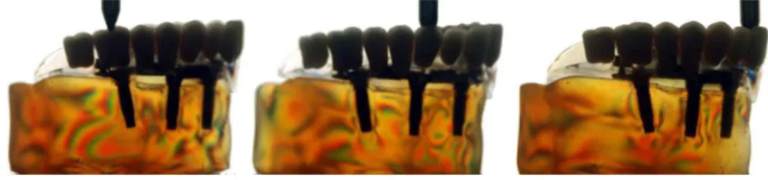
Regarding stress distribution in the model without implants, the fringes were located on the region of alveolar ridge crest (Fig.1). In the models with implants, regardless of the attach-ment system, the photoelastic fringes were observed at the apical region of the implants. In all attachment systems, the highest stress concentration occurred at the apex of the implant in the anterior region during load application at element 11 (Figs.2–6). It was also observed that the amount and distribution of stress were similar in the parallel and tilted implants (Table 1 and Figs.2–6).
4 Discussion
The hypothesis that the system with three individualized O-rings provides the lowest stress and that the highest stress would occur in the tilted implant was partially accepted since the stresses were similar in parallel and tilted implants.
It is known that the obturator prosthesis is the most used to achieve a successful rehabilitation after maxillectomy, restoring pronunciation, chewing, swallowing, and aesthetics.4,5,7,21–31As
described in Table1, the conventional obturator prosthesis pre-sented the lowest stress values.
However, the retention and, consequently, the function of these prostheses can be affected by the extent and nature of the defect, height and thickness of the residual ridge.4,6,7,11,21,22,32
Thus, the association of dental implants and attachment system is used in such cases to provide additional retention, improve support and stability of obturator.5,7,24,25
According to current results, it can be seen that the attach-ment system directly influences the number and distribution of tension, which corroborates with other studies4–9,12which have
highlighted that these systems would exert an important role in stress distribution around the anchorages.
Table 1 Number of photoelastic fringes according to the element in which the load was applied.
Attachment system
Load application point element
16 13 11
Conventional (WI) 0 1 1
OR 4 4 6
OD 5 5 4
BOC 5 5 5
BOD 6 6 7
BC 8 8 7
Fig. 1 Stress distribution in the models without implants (WI).
Fig. 2 Stress distribution in the models with three individualized O-rings (OR).
Fig. 3 Stress distribution in the models with implants splinted by bars associated with two O-rings positioned in distal cantilever (OD).
Fig. 4 Stress distribution in the models with implants splinted by bars associated with two O-rings positioned at the center of the bar (BOC).
Fig. 5 Stress distribution in the models with implants splinted by bars with clips associated with two O-rings positioned in distal cantilever (BOD).
In the present study, it was found that among the implant-retained obturators, the OR system showed the lowest number of stress fringes, followed by OD, BOC, and BOD. The BC sys-tem had the largest number of stress fringes (Table 1). These results corroborate with other studies4,5,7,14–19that also evaluated
implant-retained overdentures and found that the O-ring system transfers less stress to the implants when compared with the bar-clip system. Further, according to the authors, this may be a result of stress absorbed by the female component of the system, which usually has a rubber ring surrounded by a metal capsule. It can absorb or distribute more homogeneously the forces they are submitted to.
It was also observed that in the groups where two O-rings were associated with the bar (in the center, in cantilever with or without clip), the stress values were smaller than the bar-clip system when used alone (Figs.3–6). We believe that the BOD system has the highest value due to the smaller resilience of the clip which causes the load to be transferred to the bar and thus to the implants. Similar results were found by Ben-Ur et al.,33Celik and Uludag,13and Barão et al.,9who observed lower stress values in the bar-clip system associated with distal resilient attachments when compared with the bar-clip system. The authors also affirm that the combination of distal O-rings to the bar-clip system creates a fulcrum line in the distal portion that makes the prosthesis anteroposteriorly rotate around this fulcrum, and due to elasticity module of the ball system’s resil-ient matrix, the stress magnitude of the implants is reduced.
These results are in agreement with those found by Goiato et al.,4,5 who observed the stress distribution in different
implants’ attachment systems (O-ring, bar-clip and bar with O-ring in distal cantilever) of obturator maxillary prostheses through the photoelastic method. They concluded that the use of the association between the bar and distal O-rings favored the stress distribution.
In relation to implant inclination in the first molar region, a greater number of fringes were not observed in the implant in comparison with the axial implants (Table1). The stress distri-bution was similar in all implants (regardless of attachment sys-tem), being located in the region of the implant apex (Figs.2–6). Several studies34–39 have discussed the possible harmful
effects of using tilted implants in the biomechanics of the pros-thesis and demonstrated that the higher the angulation of the implant, the higher the stress. This does not agree with our results which showed that the inclination of the implant did not have a negative effect on the stress distribution.
The study of Koutouzis and Wennström40 compared bone
levels in implant-retained prosthesis over axial and tilted implants for 5 years and concluded that the implant angulation had no effect in periimplant bone loss.
Furthermore, the literature shows that when tilted implants are installed in association with axial implants, they allow reha-bilitation with different options of prosthesis, with high success rates, minimal complications, and high patient’s satisfaction. Therefore, it may be considered a predictable technique with an excellent prognosis in short and medium term.1–3
According to this study, when there is a need for installation of tilted implants in the posterior region of maxilla, success can be achieved for implant-retained obturators prosthesis.
It is important to highlight that this study presents some self-limitation because it is an indirect technique, so it requires sim-ilar reproduction models to be able to compare them. Another factor to consider is the limit of external load to be applied that
cannot exceed the endurance limit of the photoelastic material or it may alter the results or promote the material’s break. There is still the inability to precisely calculate the stress and compres-sion distribution in the periodontal ligament.41,42Although some
materials used for experimental models confection present modulus of elasticity close to that found in bone tissues, these still have some limitations such as the lack of differentia-tion of cortical and medullary bone, which changes the magni-tude of the load. However, the location and behavior of the stress undergo little changes in comparison to a real model.41,42
It is observed in several studies41,43–45that none of stress
’s analysis has full preponderance over others, which results in a consensus among researchers that the analyses are comple-mentary and are used in combination in their work. Thus, finite element and/or strain gauge andin vivostudies should be con-ducted to complement and to validate the results obtained in this experimental study.
5 Conclusion
It was concluded that• the system with three individualized O-rings provided
lower values of tension on the implants and supporting tissues, achieving better biomechanical results of implant-retained palatal obturators, and
• the tilted implant presented a biomechanical behavior
similar to parallel implants, within the conditions of the experiment.
Acknowledgments
To National Council of Reserach—CNPq for granting a PhD scholarship and to the State of São Paulo Research Foundation—FAPESP, for the financial support granted to this work (Process 2010/01241-3).
References
1. M. Del Fabbro et al.,“Tilted implants for the rehabilitation of edentu-lous jaws: a systematic review,”Clin. Implant Dent. Relat. Res.14(4), 612–621 (2012).
2. D. Penarrocha-Oltra et al.,“Rehabilitation of the atrophic maxilla with tilted implants: review of the literature,”J. Oral Implantol.(2011), Epub ahead of print.
3. J. Ata-Ali et al.,“Oral rehabilitation with tilted dental implants: a meta-analysis,”Med. Oral Patol. Oral Cir Bucal.17(4), 582–587 (2012). 4. A. A. Pesqueira et al.,“Stress analysis in oral obturator prostheses:
imaging photoelastic,”J. Biomed. Opt.18(6), 061203 (2013). 5. M. C. Goiato et al.,“Photoelastic analysis to compare implant-retained
and conventional obturator dentures,”J. Biomed. Opt.17(6), 061203 (2012).
6. M. C. Goiato et al.,“Retention systems to implant-supported craniofa-cial prostheses,”J. Craniofacial Surg.20(3), 889–891 (2009). 7. M. C. Goiato et al.,“Photoelastic analysis of stress distribution in
differ-ent retdiffer-ention systems for facial prosthesis,”J. Craniofacial Surg.20(3), 757–761 (2009).
8. M. C. Cehreli et al., “A systematic review of marginal bone loss around implants retaining or supporting overdentures,” Int. J. Oral Maxillofacial Implants25(2):266–277 (2010).
9. V. A. Barão et al.,“Effect of different mucosa thickness and resiliency on stress distribution of implant-retained overdentures-2D FEA,”
Comput. Methods Programs Biomed.92(2), 213–223 (2008). 10. K. M. Lyons, J. Beumer, and A. A. Caputo,“Abutment load transfer by
11. S. M. Ortegon, J. W. Martin, and J. S. Lewin,“A hollow delayed sur-gical obturator for a bilateral subtotal maxillectomy patient clinical report,”J. Prosthet. Dent.99(1), 14–28 (2008).
12. V. A. Barão et al.,“Finite element analysis to compare complete denture and implant-retained overdentures with different attachment systems,”
J. Craniofacial Surg.20(4), 1066–1071 (2009).
13. G. Celik and B. Uludag,“Photoelastic stress analysis of various reten-tion mechanisms on 3-implant-retained mandibular overdentures,”
J. Prosthet. Dent.97(4), 229–235 (2007).
14. M. Daas et al.,“A complete finite element model of a mandibular implant-retained overdenture with two implants: comparison between rigid and resilient attachment configurations,”Med. Eng. Phys.30(2), 218–225 (2008).
15. H. J. A. Meijer et al.,“Stress distribution around dental implants: in-fluence on superstructure, length of implants, and height of mandible,”
J. Prosthet. Dent.68(1), 96–102 (1992).
16. R. Kenney and M. W. Richards,“Photoelastic stress patterns produced by implant-retained overdentures,”J. Prosthet. Dent.80(5), 559–564 (1998). 17. G. Meniccuci et al.,“Mandibular implant-retained overdenture: finite element analysis of two anchorage systems,”Int. J. Oral Maxillofacial Implants13(3), 369–376 (1998).
18. J. A. Porter, V. C. Petropoulos, and J. B. Brunski, “Comparison of load distribution for implant overdenture attachments,” Int. J. Oral Maxillofacial Implants17(5), 651–662 (2002).
19. M. Tokuhisa, Y. Matsushita, and K. Koyano,“In vitro study of mandibu-lar implant overdenture retained with ball, magnet, or bar attachments: comparison of load transfer and denture stability,”Int. J. Prosthodont. 16(2), 128–134 (2003).
20. V. A. Barão et al.,“Comparison of different designs of implant-retained overdentures and fixed full-arch implant-supported prosthesis on stress distribution in edentulous mandible–a computed tomography-based three-dimensional finite element analysis,”J. Biomech.46(7), 1312– 1320 (2013).
21. E. Bedrossian and P. I. Brånemark,“Systematic treatment planning pro-tocol for patients with maxillofacial defects: avoiding living a life of seclusion and depression,” Atlas Oral Maxillofacial Surg. Clin. North Am.20(1), 135–158 (2012).
22. F. Keyf,“Obturator prostheses for hemimaxillectomy patients,”J. Oral Rehabil.28(9), 821–829 (2001).
23. O. C. Dilek and E. Tezulas,“A mini implant-supported obturator appli-cation in a patient with partial maxillectomy due to tumor: case report,”
Oral Surg. Oral Pathol. Oral Radiol. Endod.103(3), 6–10 (2007). 24. M. E. Kreissl et al.,“Zygoma implant-supported prosthetic
rehabilita-tion after partial maxillectomy using surgical navigarehabilita-tion: a clinical report,”J. Prosthet. Dent.97(3), 121–128 (2007).
25. C. T. Nguyen, C. F. Driscoll, and D. P. Coletti,“Reconstruction of a maxillectomy patient with an osteocutaneous flap and implant-retained fixed dental prosthesis: a clinical report,”J. Prosthet. Dent.105(5), 292–295 (2011).
26. A. B. Kornblith et al.,“Quality of life of maxillectomy patients using an obturator prosthesis,”Head Neck18(4), 323–334 (1996).
27. S. N. Rogers et al.,“Health-related quality of life after maxillectomy: a comparison between prosthetic obturation and free flap,” J. Oral Maxillofacial Surg.61(2), 174–181 (2003).
28. C. A. Landes,“Zygoma implant-supported midfacial prosthetic reha-bilitation: a 4-year follow-up study including assessment of quality of life,”Clin. Oral Implants Res.16(3), 313–325 (2005).
29. J. Irish et al.,“Quality of life in patients with maxillectomy prostheses,”
Head Neck31(6), 813–821 (2009).
30. B. Lethaus et al.,“Surgical and prosthetic reconsiderations in patients with maxillectomy,”J. Oral Rehabil.37(2), 138–142 (2010). 31. M. C. Goiato et al.,“Patient satisfaction with maxillofacial prosthesis.
Literature review,”J. Plast. Reconstr. Aesthet. Surg.62(2), 175–180 (2009).
32. B. Bagis, E. Aydoğan, and U. Hasanreisoğlu,“Rehabilitation of a con-genital palatal defect with a modified technique: a case report,”Cases J. 1(1), 39 (2008).
33. Z. Ben-Ur, C. Gorfil, and A. Shifman,“Anterior implant-supported overdentures,”Quintessence Int.27(9), 603–606 (1996).
34. R. A. Markarian et al.,“Stress distribution after installation of fixed frameworks with marginal gaps over angled and parallel implants: a photoelastic analysis,”J. Prosthodont.16(2), 117–122 (2007). 35. E. B. Las Casas et al.,“Comparative 3D finite element stress analysis
of straight and angled wedge-shaped implant designs,”Int. J. Oral Maxillofacial Implants23(2), 215–225 (2008).
36. C. M. Bellini et al.,“A finite element analysis of tilted versus non-tilted implant configurations in the edentulous maxilla,”Int. J. Prosthodont. 22(2), 155–157 (2009).
37. M. Cruz et al.,“Finite element stress analysis of dental prostheses sup-ported by straight and angled implants,” Int. J. Oral Maxillofacial Implants(2009).
38. S. Graves et al.,“Maxillary all-on-four therapy using angled implants: a 16-month clinical study of 1110 implants in 276 jaws,” Dent. Clin. North Am.55(4), 779–794 (2011).
39. E. P. Pellizzer et al.,“Influence of implant angulation with different crowns on stress distribution,”J. Craniofacial Surg.22(2), 434–437 (2011).
40. T. Koutouzis and J. L. Wennström,“Bone level changes at axial- and non-axial-positioned implants supporting fixed partial dentures. A 5-year retrospective longitudinal study,”Clin. Oral Implants Res.18(5), 585–590 (2007).
41. A. A. Pesqueira et al.,“The use of stress analysis methods to evaluate the biomechanics of oral rehabilitation with implants,” J. Oral Implantol.(2012), Epub ahead of print.
42. M. C. Cehreli et al.,“Human ex vivo bone tissue strains around natural teeth vs. immediate oral implants,”Clin. Oral Implants Res.16(5), 540– 548 (2005).
43. S. R. Bernardes et al.,“Photoelastic analysis of stress patterns from dif-ferent implant-abutment interfaces,”Int. J. Oral Maxillofacial Implants 24(5), 781–789 (2009).
44. K. Akça and M.C. Çehreli,“A photoelastic and strain-gauge analysis of interface force transmission of internal-cone implants,” Int. J. Periodontics Restorative Dent.28(4), 391–399 (2008).