Vol. 4, No. 1, June 2007, 85-94
Hybrid Reed - Solid-State Devices are a New
Generation of Protective Relays
Vladimir Gurevich
1Abstract: Research and development in the field of electromechanical protective relays has not been conducted for tens of years. Author’s approach allows viewing the problem of re-equipment of relay protection in a new way. In the author’s opinion combination of reed switches with magnetic circuits and semiconductor elements opens new avenues in development of the promising protective relays featuring reliability, simplicity and low cost. Examples of protective relays made with these elements are given below.
Keywords: Hybrid relays, Reed switch, Solid-state device, Relay protection, Over-current relay.
1 Introduction
In the past few years small-sized standard case TO-247, TO-220 thyristors and transistors intended for soldering on the printed-circuit-board for the switching of current of tens of amperes at voltages of 1200-1600V have appeared.
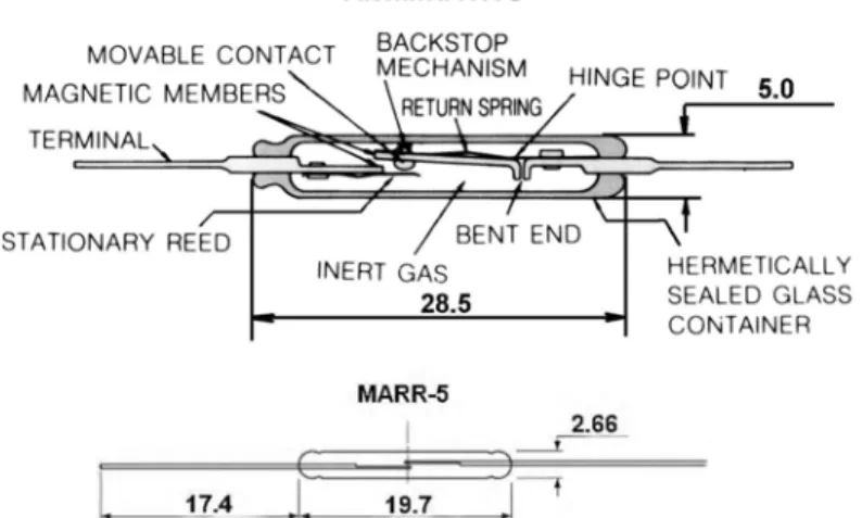
Various companies manufacture miniature high-speed (fractions of milliseconds) vacuum reed switches that can withstand voltages of 1000 - 2500V which can serve as precision threshold (pickup) elements in the protective relays. The Japanese company Yaskawa and its branches manufacture a series of middle size powerful reed switches for switching currents of up to 5A at a voltage of 250 V (Fig. 1).
When using reed switches it should be kept in mind that their high relia-bility will be guarantied only when observing the restrictions imposed by the switching ability determined in the technical specifications. As in semi-conduc-tor switches, the reed switches quickly fail when the allowed switching parame-ters are exceeded even for a short time. At the same time, even though modern reed switches are electromechanical elements, their reliability and number of switching cycles is closer to that of semi-conductor elements, and so are many of their parameters, such as withstanding electromagnetic interferences, surge
1
capability, etc. It should be pointed out they considerably surpass semi-conduc-tors in withstanding surges. Because of extraordinary features of the reed switch relays, not possessed by usual electromechanical relays, such as high speed, precise and stable pickup value, and high release factor on an alternating current, etc., many devices for protection and automation systems in the industry, power engineering and military techniques have been developed on their basis.
Table 1
Main parameters of the modern power thyristors, suitable for mounting on PCB.
Parameter/
Thyristor type 30TPS12 25TTS12 70TPS16
CS60- 16io1 BTW 69-1200 CS 29-12io1C
Case
TO-247AC
TO-220AC
SUPER
247 PLUS247 TOP3
ISOPLUS 220 Max. off-state peak
voltage, V 1200 1200 1600 1600 1200 1200
Max. on-state rms
current, A 30 25 70 75 50 35
Peak, ½ cycle surge
current, A 300 300 1200 1500 580 200
dv/dt, V/µs 500 500 500 1000 1000 1000
di/dt, A/µs 150 150 150 150 50 150
Leakage current
(t = 25ºC), A 0.5 0.5 1.0 0.2 5 2
Holding current, mA 100 150 200 200 150 50
Turn-on time, µs 0.9 0.9 - 2 - 2
Table 2
Main parameters of the modern power high-voltage IGBT.
Parameter/ Transistor type IXSK35N1 20AU1 APT35 GN120N FGA25N 120ANTD IXGH 25N160 FGA50N 100BNTD
Case TO-246AA TO-247 TO-3P TO-247 TO-3P
Max.
collector-emitter voltage, V 1200 1200 1200 1600 1000
Continuous collector
current, A 35 94 25 75 50
Pulsed collector
current, A 140 105 90 200 100
Total power
dissipation, W 300 379 312 300 156
Collector-emitter ON
voltage, V 4 2.5 – 4.7 2.15 2.5 – 4.7 2.0
Turn-ON
delay time, ns 80 24 50 47 140
Turn-OFF
Fig. 1 – Modern reed switches, recommended for use in the protective relays. At the top: gas filled power reed switch R15U (Yaskawa);
at the bottom: miniature high-speed vacuum reed switch MARR-5 (Hamlin Inc.). Table 3
Main parameters of high-speed vacuum high-voltage reed switches.
Parameter/
Reed switch type MRA5650G KSK-1A75 HYR2016 HYR1559 MARR-5 R1-48C
Contact form NO NO NO NO NO NO
Max. switching
voltage, V 1000 1000 1000 1500 1000 250
Max. switching
current, A 1 0.5 1 0.5 0.5 1
Max. switching
power, W 100 10 25 10 10 70
Dielectric
strength, V 1500 1500 2500 1500 2000 780
Operate time, ms 0.6 0.5 0.8 0.4 0.75 0.35
Release time, ms 0.05 0.1 0.3 0.2 0.3 0.03
Dimensions, mm D = 2.75, L = 21
D = 2.3, L =14.2
D = 2.6, L = 21
D = 2.3, L =14.2
D = 2.66, L = 19.7
D = 2.7, L = 20.5 Pull in value
(AT range) 20 – 60 15 - 40 15 - 70 15 - 50 17 - 38 27 - 80
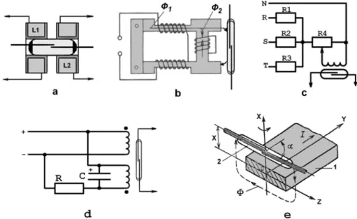
summing element, etc. A reed switch with a special magnetic circuit (Fig. 2b) appears to be insensitive to the DC (aperiodical) component of the current in the coil. The reed switch, connected with to a simple circuit, Fig. 2c, responds to the voltage asymmetry. In the circuit, Fig. 2d, the reed switch picks up only at rapid changes of current (voltage) in a control circuit which is distinctive for emergency modes and does not respond at slow changes of the current, related to the changes in load, and as described above. The reed switch is also directly responsive to the magnetic field of the current passing in bus bar without additional windings (Fig. 2е).
Fig. 2 – Examples of various applications of reed switches in the protection devices. Let us consider concrete examples of the most widespread kinds of protective relays based on the suggested technology.
2
Protective Relays Based On Hybrid Technology
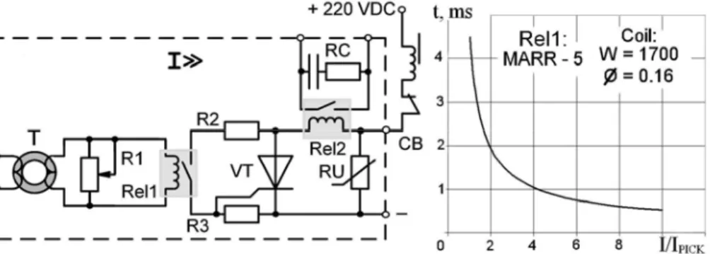
2.1 Instantaneous current relay (Fig. 3).
The over-current relays without time delays are widely used for the protection of electric networks and electric equipment against overloads. This version of the relay is intended for directly energizing the trip coil of the high-voltage circuit breaker (CB).
frequency. Upon the initial closing of the circuit by the reed switch, thyristor VT will turn-ON and energize the CB trip coil. The thyristor only switches this coil ON; it is switched OFF by the own auxiliary-contact of the CB. Rel2 is an auxiliary relay, intended for signaling or blocking circuits and it uses a medium capacity reed switch such as GC1513. Its coil has very low resistance and it is designed for the short-term carrying of a direct current in a range from 0.5 up to 15 A (typical currents of CB trip coils of various types) at which this reed switch operation is reliable. Adjustment of pickups (coarsening the relay) is carried out with the help of potentiometer R1. In the relay thyristor such as 30TPS12 (in TO-247AC case) is used with rated current 30А and the maximal withstanding voltage of 1200V and miniature vacuum reed switch such as MARR-5. The input CT is made on a low-frequency ferrite ring with the external diameter of 32 mm.
Fig. 3 – The simplest hybrid protective relay: instantaneous current relay. The basic circuit diagram and experimental time-current characteristic curve.
I/I PICK – multiples of pickup setting.
RC-circuit serves for protection of the auxiliary contact (reed switch) from spark erosion at switching of inductive loads. Varistor RU such as SIOV-Q20K275 protects the device from spikes in the DC circuit. Its clamping voltage does not exceed 350-420V DC. This voltage level should be higher than the rated voltage of a DC network, but lower than the maximal withstanding voltages of the thyristor and the reed switch. As shown in experimental time-current characteristic curve, the relay speed is higher than that of the electromechanical, static or microprocessor-based devices, it does not need power supply, is insensitive to high-frequency interferences and spikes in a current circuit, and remains reliable at strong distortions of current.
The second CT (T2) serves as an energy source necessary for the operation of the power reed switch.
Closing and opening reed switch (Rel1) with double the current frequency at energizing does not suit to the operation of relay Rel2. Therefore a special active filter can be used between pickups element Rel1 and output relay Rel2. The filter formed with capacitor C2 (22 µF), resistors R2, R3 and transistor VT which can be any low-power transistor for voltages not less than 100V with current gain (hFE) not less than 100, for example, such as ZTX753, ZTX953.
With a low-power Darlington transistor (for example, such as ZTX605), as shown in Fig. 4, the capacity 2 can be considerably reduced. By means of this filter the current pulsation in the reed switch circuits of Rel1 will be transformed to a stable current in the coil circuit of relay Rel2.
Fig. 4 – Instantaneous current relay with high release ratio:
the basic circuit diagram and experimental time-current characteristic curve. I/I PICK – multiples of the pickup setting.
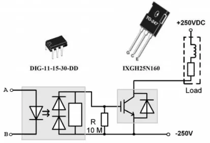
the relay with an uncharged capacitor the time delay is approximately twice as long. Such an acceleration of operation in case of repeated pickups at short circuit is a positive property of the protective relay. Even in view of increasing the operation time at the initial pickup, the relay speed still remains very high. Modern IGBT-transistors and complete modules used for their operation (so-called "drivers") enable realization of a very simple switching output unit of the relay on a contact less basis (Fig. 5).
Fig. 5 – An embodiment of output switching unit of the relay based on the modern IGBT-transistor (IXGH25N160) and specialized driver with the dynamic discharging
(DIG-11-15-30-DD) for this transistor control.
2.3 Current relays with independent and
dependent time delay (Fig. 6)
Similar to the above design, the relay contains two independent current transformers: the first one, 1, is used as a source of control value for the pickups module on the reed switch, Rel1, and the second, 2, for feeding the time delay unit.
switch. In order to turn this device into a relay with time delay depending on the current it is necessary turn the micro-switch, S, to OFF.
Fig. 6 – Universal protective current relay with the time delay: the basic circuit diagram and set of experimental time-current characteristic curves. For the relay with the
dependent time-current characteristic curves the various values of capacity
С2 (in µF) are as follows:1 - 4400; 2 - 3200; 3 - 2200; 4 - 1000; 5 - 300.
2.4 Relay of a power direction (Fig. 7).
Even such complex function as detection of power direction can be realized very simply by means of the hybrid technology.
Fig. 7 – The relay of power direction: basic circuit diagram of measuring the threshold module and experimental dependence of an output voltage of transformer T3 on an
angle shift between two voltages on its primary windings.
As it is known, the power direction is determined by the angle of phase displacement between the current and the voltage; therefore, actually, the power direction relay responds to the change of angle between the current and the voltage. It turns out that application of two equivalent phase-shifted voltages to two primary windings of the intermediate transformer T3 causes the output voltage on the third winding to depend very strongly on the phase displacement between these voltages (Fig. 8).
This is necessary only in order to prevent the effect of a change of the input voltage supplied from current transformer, 1, and voltage transformer, 2, at a level of the output voltage of transformer T3. The simplest solution of this problem is provided by means of two back-to-back connected Zeners as it is shown on Fig. 7. A pickup relay can be adjusted by means of potentiometer R.
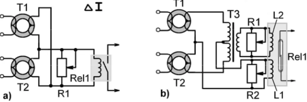
2.5 Relay of differential protection (Fig. 8).
The use of two current transformers ( 1 and 2) connected to the input of the pickup module of any of the devices described above enables realizing a two-input relay of differential protection (Fig. 8а).
restraint, which shift the working point of the relay proportionally to the current carried directly through the protected object (Fig. 8b).
Fig. 8 – Measuring modules for the relay of differential protection: to the left the simplest embodiment, to the right – an embodiment with restraint.
3 Conclusion
Description of quite interesting and promising devices based on the suggested elements could be continued. However, the purpose of this publication is not to present the advantages of reed switches, but to prove that on the basis of a combination of modern reed switches and modern power semi-conductor elements a new generation of hybrid protective relays not including complex mechanisms can be easily created that can replace the out-of-date electro– mechanical relays at the upper level with retaining their high noise and surge stability, maintainability and other positive features. The use of the new generation of the relays would allow sparing considerable financial expenses connected with necessity of purchasing the expensive microprocessor-based protective devices. Thus, further perfection of automatic control systems in electric networks through by equipping them with microprocessor recorders of emergency modes, optical communication systems and other modern systems can be gradually accomplished, during accumulation of financial resources independently of the relay protection. In the author’s opinion the above examples of the protective relays developed and tested by the author, can support our conclusion.
4 References
[1] V. Gurevich: Protection Devices and Systems for High Voltage Applications, pp. 293, Marcel Dekker, New York, 2003.