Automatic convey or System with In
–
Process Sorting Mechanism
using PLC and HMI System
Y V Aruna*, Beena S**
*(Department of Electrical & Electronics Engg., Cambridge Institute Of Technology, Bangalore-36) **(Department of Electrical & Electronics Engg., Cambridge Institute Of Technology, Bangalore-36)
ABSTRACT
Programmable logic controllers are widely used in many manufacturing process like machinery packaging material handling automatic assembly. These are special type of microprocessor based controller used for any application that needs any kind of electrical controller including lighting controller and HVAC control system. Automatic conveyor system is a computerized control method of controlling and managing the sorting mechanism at the same time maintaining the efficiency of the industry & quality of the products.HMI for automatic conveyor system is considered the primary way of controlling each operation. Text displays are available as well as graphical touch screens. It is used in touch panels and local monitoring of machines. This paper deals with the efficient use of PLC in automatic conveyor system and also building the accuracy in it.
Keywords:
Automatic conveyor, Human Machine Interface, High Voltage Alternating Current, ProgrammableLogic Controller.
I.
INTRODUCTION
Automating every sector of industry is an important step toward increasing efficiency and reducing human related errors, here we try to automate the sorting process by using PLC. In many industries job pieces of various sizes are moved on same conveyor belt these need to separate at various locations in the manufacturing line. For this purpose we are using the automated process which is used to sort the materials which are of different sizes. After completion of manufacturing the products automatically move on the conveyor belts. Sensors at different places sense and detect the job pieces of different sizes.
They get sorted at different places based upon their sizes. The entire process is controlled by the program dumped in PLC. A very commonly used method of programming PLC’s is based on the use of ladder diagrams. Writing a program is the equivalent to drawing a switching circuit. Circuits are connected as horizontal lines, that is, the rungs of the ladder, between these two vertical lines. In drawing a ladder diagram, certain conventions are adopted.
1.1 Programmable Logic Controller System A programmable logic controller (PLC) is an industrial computerised control system that continuously monitors the states of input devices and makes decisions based upon a custom program to control the state of output devices. A fixed PLC is usually small, has little memory, and a limited number of inputs and outputs, or I/O as typically referred to fig.1.1. The CPU, power supply, and I/O system are all constructed as a single entity.
Fig.1.1 PLC System
The input sensing devices is fed to the input module which acts like an optical isolation. What is connected to the main device CPU and memory data. The monitor who acts like a programming device where it displays the given. Then the entire system is connected to the output block where the outputs are the lamp, motor, etc.
II.
HUMAN MACHINE INTERFACE
The HMI (Human Machine Interface) system represents the interface between man (operator) and process (machine/plant). The PLC is the actual unit which controls the process. Hence, there is an interface between the operator and WinCC flexible (at the HMI device) and an interface between WinCC flexible and the PLC. An HMI system assumes the following tasks: Process visualization
Operator control of the process
Displaying alarms
Archiving process values and alarms
Process values and alarms logging
Process and machine parameter management
WinCC flexible Engineering System
1.2.1 Win CC flexible Engineering System
The Win CC flexible Engineering System is the software for handling all your essential configuring tasks. The Win CC flexible edition determines which HMI devices in the SIMATIC Communication with the automation systems. On-screen visualization of images Operating the process.
For example, by setting set point values or opening and closing valves. Archiving of current runtime data, e.g. process values and alarm events.
1.2.1.1 Automation concept with Wincc flexible Win CC flexible supports the configuration of many different automation concepts. The following automation concepts can be implemented by default using WinCC flexible.
Control with one HMI device
An HMI device which is directly connected to the PLC via the process bus is referred to as a single-user system shown in fig.1.2.1.1.Single-single-user systems are generally used near production, but can also be deployed to operate and monitor independent part processes or system sections.
Fig.1.2.1.1Single-user HMI System
1.2.2 HMI System with centralized functions An HMI system is connected to a PC via Ethernet. The upstream PC assumes central functions, e.g. recipe management. The necessary recipe data records are provided by the subordinate HMI system as in fig 1.2.2.
Fig.1.2.2. HMI System with centralized functions
1.2.2.1 Support for Mobile Units
Mobile units are mainly implemented in large production plants, long production lines or in conveyor technology, but can also be implemented in systems in which direct visual contact with the process is necessary. The machines to be operated are equipped with several interfaces to which the Mobile Panel 170, for example, can be connected.
1.2.2.2 Remote access to HMI
By using the Smart Service option, it is possible to connect to an HMI device from a workstation via a network (Internet, LAN).
Example: A medium-sized production company has a service contract with an external service company. When servicing is required, the service technician responsible can remotely access the HMI device and display its user interface directly on his workstation. In this way, updated projects can be transferred more quickly which, in turn, reduces machine downtime.
III.
HARDWARE CONFIGURATION
Fig.1.3.Block diagram of Automatic conveyor system with PLC& HMI
1.3.1 Inductive Proximity Sensor [Metal Sensor]
A metal detector is an electronic
instrument which detects the presence of metal nearby. Metal detectors are useful for finding metal inclusions hidden within objects. Proximity sensors (refer fig.1.3.1) are generally constructed with four main elements:
a coil and ferrite core assembly
an oscillator
a convertor/trigger circuit (detector)
output device
Fig.1.3.1.Schematic diagram of Proximity sensor
1.3.1.1Specifications
Table.1.3.1.1 Specification of Proximity sensor
1.3.2 Ultrasonic Level Sensor
The principle of operation of the ultrasonic sensor system is to use the ultrasonic pulses which are transmitted by the transducer to the surface to be monitored and are reflected back to the transducer, the time period between transmission and reception of the sound pulses is directly proportional to the distance between the transducer and surface, A micro-controller computes this time period for all echoes received and analyses them to determine which is the correct reflection from the material surface, it uses this data as the basis for giving control outputs and displays in usable engineering units.Refer Table 1.3.2 for the general specifications of the sensor.
General Specification Sensing range 70…1000 mm Adjustment range 90…1000 mm Unusable area 0 … 70 mm Standard Target
area
100mm x 100mm
Transducer frequency
Approx.KHZ
Response delay Approx.125ms
Table.1.3.2. Specification of Ultrasonic level sensor
1.3.3 Geared DC Motor
30 RPM Side Shaft 37mm diameter compact DC Gear Motor is suitable for small robots / automation systems Motor runs smoothly from 4V to 12V and gives 30 RPM at 12V.Motor has 6mm diameter, 22mm length drive shaft with D shape for excellent coupling.
1.3.4 Pneumatics:
In a pneumatic system, energy is stored in a potential state under the form of compressed air. Working energy (kinetic energy and pressure) results in a pneumatic system when the compressed air is allowed to expand. To perform any applicable amount of work then, a device is needed which can supply an air tank with a sufficient amount of air at a desired pressure. There are many different cylinder types. The cylinders used in our paper are listed below:
1. Single acting spring return cylinder 2. Double acting cylinder
3. Directional Control Valves 4. FOUR Way Valve
Fig.1.3.4 Pneumatic system
1.3.5.Basic procedures for configuring hardware Window for configuring a programmable controller involves the use of two windows. The station window in which you place racks for the station structure. The “hardware catalogue” window from which you select the required hardware components,for example racks , modules and interface sub modules displaying the hardware catalogue if the “hardware catalogue” window is not displayed, select the menu command view > catalogue. This command toggles the display of the hardware catalogue on and off.fig.1.3.5 shows the hardware configuration of the system.
Basic steps for configuring a station independent of which structure a station has you always configure using the following steps
1. Select a hardware component in the “hardware catalogue” window.
Fig.1.3.5.Overview of hardware configuration
IV.
Design of Automatic Conveyor
System
The main objective of the system is automatic sorting of materials which can be applied to industries as in fig1.4.1.Here, by operating push button switch the conveyor starts to move and the items are being sorted.
Fig. 1.4.1 Design of Automatic Conveyor System
The ultrasonic level sensor and inductive proximity metal sensor are mounted on the model and are connected to the SEIMENS PLC kit. When the objects are detected by the level sensor the signal is sent to the SEIMENS PLC kit where according to the programmed ladder logic the conditions are analyzed and the output is given to pneumatic valves which activates pistons for sorting.
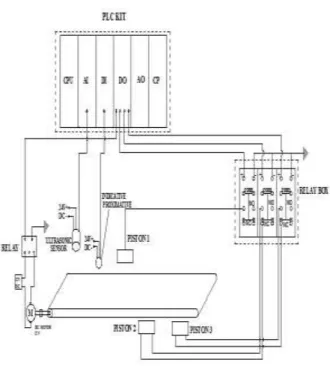
Fig. 1.4.2.Circuit diagram
Meanwhile, the metal detector which is connected to SEIMENS PLC kit. when the objects that contain hidden metal in them are detected and signal is given to the PLC where according to the ladder logic the objects with metal are rejected from the conveyor by activating the pistons and hence carrying out the sorting mechanisms. Since we are sorting the height of the object. If any objects which are over height than the required height are rejected from the conveyor to avoid inconvenience.
For example consider the height of the objects 4cm, 8cm and 12cm for sorting as shown in fig.1.4.3. When the ultrasonic level sensor senses the height of the object if it is 4cm it should be segregated in bin 1, 8cm at bin 2 and 12cm at bin 3. Suppose the objects contain hidden metal in them then it is sensed by the metal sensor and rejected before going to sorting process
V.
HMI DESIGN
The following are the screens for our HMI panel where the screens are programmed and the whole automation can be controlled by HMI.
SCREEN 1
The welcome screen is the screen which navigates the operator to the next screens.
SCREEN 2
The authorization screen which has a user id and password for the administrator and other users to use the HMI panel.
SCREEN 3
The MENU screen helps the operator to control the sorting system by providing the options on the screen.
SCREEN 4
The CONVEYOR MONITORING screen provides access for starting and stopping the sorting process.
SCREEN 5
The REPORT screen provides information of the number of parts sorted.
SCREEN 6
The LEVEL SETTINGS gives control for the operator to enter desired height of the parts to be sorted.
SCREEN 7
VI.
ADVANTAGES
Time saving and efficient.
Increases in production capacity and quality.
Decreases in total manufacturing cost.
Less manual work.
Easy analysis.
Improves productivity
VII.
DISADVANTAGES
Costly for small scale industries
The sorting mechanism is time based hence frequent monitoring is required.
PLC devices are proprietary
Unemployment rate increases
VIII.
APPLICATIONS
Manufacturing / machining
Food / beverage
Textile industry
Printing industry
IX.
CONCLUSION
In present day scenario automation is of vital importance. Automation is very efficiently put up in practice in many ways; one of them is automatic conveyor system with in-process sorting mechanism. The main advantage of PLC is it is been controlling multiple inputs and outputs, the entire conveyor model can be controlled by a single PLC along with sensors installed throughout.
The use of PLC and HMI in automation applications has grown in recent years. The economics of PLC based solutions mean that automatic conveyor and HMI solutions can be applied even more widely. This will help the utilities respond to the challenges presented by the deregulations. As the use of PLCs in automatic conveyor increases the criteria for selection of control system integrators, engineering firms and consultants will become and extremely important factor in success of PLC based automation and HMI projects. One of the most important criteria in the control
system integrator- the engineering firm the consultant has sound business practices in place. They should also have a project management methodology in place to assure the success of these projects.
REFERENCES
[1]. Keller, William L Jr.Grafcet, A Functional Chart for Sequential Processes, 14th Annual International Programmable Controllers Conference Proceedings, 1984, p. 71-96. [2]. Kinner, Russell H., P.E. Designing
Programmable Controller Application Programs Using More than One Designer.14th Annual International Programmable Controllers Conference Proceedings, 1985, p. 97-110.
[3]. Maher, Michael J.Real-Time Control and Communications. 18th Annual ESD/SMI International Programmable Controllers Conference Proceedings, 1989, p. 431-436. [4]. Yang, G., Rasis, Y., “Teaching PLC in
Automation –A Case Study”, ASEE Annual Conference &Exposition, 2003
[5]. Guo, L., Pecen, R., “Design Projects in a Programmable Logic Controller (PLC) Course in Electrical Engineering Technology”, ASEE Annual Conference & Exposition, 2008
Books:
[1]. W. Bolton,Programmable Logic Controllers, (Fifth Edition, Newnes, 2009 ISBN 978-1-85617-751-1,Chapter 1)
[2]. Johnson, C. D., Process Control Instrumentation Technology, (Prentice Hall, 2006).