Finite Element Analysis and Topography Optimization of Lower
Arm of Double Wishbone Suspension Using Abacus and
Optistruct
Sagar Darge*, S.C. Shilwant**, S. R. Patil***
*PG Scholar, ME Automotive Engineering, Sinhgad Academy of Engineering, Kondhwa, Pune, Maharashtra, India-411048
**Professor, H.O.D. Mechanical Engineering, Sinhgad Academy of Engineering, Kondhwa, Pune, Maharashtra, India-411048
***Assistanant Professor, Mechanical Engineering, Sinhgad Academy of Engineering, Kondhwa, Pune, Maharashtra, India-411048
ABSTRACT
The suspension system is one of the most important components of vehicle, which directly affects the safety, performance, noise level and style of it. The vehicle suspension system is responsible for driving comfort and safety as the suspension carries the vehicle-body and transmits all forces between body and road. Structure optimization techniques under static load conditions have been widely used in automotive industry for lightweight and performance improvement of modern cars. However, these static load conditions could not represent all the severe situations of automobile parts which subjected to complex loads varying with time, especially for lower control arm of front suspension. This paper deals with Finite Element Analysis of the Lower arm suspension of double wishbone suspension which consist the stress optimization under static loadings. Lower arm suspension has been modeled using Unigraphics .In first stage of analysis area of maximum stress was identified. These analysis were carried using Altair Hyperworks and solver used is Abacus. In order to reduce stresses and to improve structural strength Topography optimization approach is carried out in Hyperworks in which a design region for a given part is defined and a pattern of shape variable-based reinforcements within that region is generated to increase Stiffness.
Keywords
- Suspension, Wishbone, Hyperworks, TopographyI.
INTRODUCTION
The Wishbone lower arm is a type of independent suspension used in motor vehicles. The general function of control arms is to keep the wheels of a motor vehicle from uncontrollably swerving when the road conditions are not smooth. The control arm suspension normally consists of upper and lower arms. The upper and lower control arms have different structures based on the model and purpose of the vehicle. By many accounts, the lower control arm is the better shock absorber than the upper arm because of its position and load bearing capacities
In the automotive industry, the riding comfort and handling qualities of an automobile are greatly affected by the suspension system, in which the suspended portion of the vehicle is attached to the wheels by elastic members in order to cushion the impact of road irregularities. The specific nature of attaching linkages and spring elements varies widely among automobile models. The best rides are made possibly by independent suspension systems, which permit the wheels to move independently of each other. In these systems the unsprung weight of the vehicle is decreased, softer springs are permissible,
and front-wheel vibration problems are minimized. Spring elements are used for automobile suspension, increasing order of their ability to store elastic energy per unit of weight.
Suspension arm is one of the main components in the suspension systems. It can be seen in various types of the suspensions like wishbone or double wishbone suspensions. Most of the times it is called as A-type control arm. It joins the wheel hub to the vehicle frame allowing for a full range of motion while maintaining proper suspension alignment. Uneven tyre wear, suspension noise or misalignment, steering wheel shimmy or vibrations are the main causes of the failure of the lower suspension arm. Most of the cases the failures are catastrophic in nature.
So the structural integrity of the suspension arm is crucial from design point of view both in static and dynamic conditions.
As the Finite Element Method (FEM) gives better visualization of this kind of the failures so FEM analysis of the stress distributions around typical failure initiations sites is essential. Therefore in this dissertation work it is proposed to carry out
the structural analysis of lower suspension arm of light commercial vehicle using FEM.
Topography optimization is an advanced form of shape optimization in which a design region for a given part is defined and a pattern of shape variable-based reinforcements within that region is generated. The approach in topography optimization is similar to the approach used in topology optimization, except that shape variables are used rather than density variables. The design region is subdivided into a large number of separate variables whose influence on the structure is calculated and optimized over a series of iterations. It is a mathematical approach to optimize bead patterns in plate structures. A finite element model of the baseline structure is built. Loads and boundary conditions are applied. The design-space finite- elements where beads can exist are selected as the optimization domain. Bead parameters are set up (height, width, draw angle, draw direction)
II.
OBJECTIVE
• Study the component design and its function for identifying potential areas for modification • Secure geometry and import the same over the
pre-processor for Discretization
• Solve the Model for securing the benchmark results
• Evolve a Test plan for validating the F.E. Methodology
• Revise the values for any of the significant parameters for noting its effect on the objective • Upon finding results for structural analysis, use
the inputs for pursuing mass optimization • Topography Optimization.
III.
METHODOLOGY
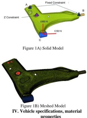
To determine stresses and to study various forces acting on lower control arm CAD model of lower control arm designed in Unigraphics was imported in Hypermesh for geometric cleanup and meshing. Meshed model of the lower arm essentially consist of 20327 nodes and 58221 elements. Tetra elements give enhanced result as compared to other types of elements, therefore the elements used in this analysis is tetra elements.
The material Mild Steel was used for lower control arm. Calculated forces and boundary conditions were applied on meshed model in HYPERMESH as shown in figure 1A and 1B. Static and modal analysis was performed by using Abacus. Design parameters obtained from above Finite Element Analysis were compared for above stated materials and best one was selected. Topography optimization of the model was carried out using OPTISTRUCT module of HYPERWORKS software.
Figure 1A) Solid Model
Figure 1B) Meshed Model
IV.
Vehicle specifications, material
properties
Vehicle parameters, assumptions are shown in Table 1 and Table 2 for a typical automobile component.
Table 1: Vehicle Specification
Table 2: Assumption made for calculations
Wheel base 2400
Track front 1400
Track rear 1380
Front Overhang 800
Rear Overhang 490
Overall length 3690
Over body 1665
Overall height - 1485
Min. turning circle dia 9.8 m
Min. turning clearance 10.2 m
Ground clearance 165
Kerb Weight 1005 Kg
Gross weight 1405 Kg
Parameters Description
R Radius of curvature (m) Φ Angle of banking (Degree) θ Slope (Degree)
Μ Coefficient of friction between Tyres and road
F Retardation By braking (m/s2)
1). Vertical Force – 1000 N 2). Horizontal Force – 1250 N 3) Material: - Mild Steel 4) Density: - 7850 Kg/ M3
5) Young’s Modulus: - 210x103 MPa 6) Yield Stress: - 340 MPa
7) Poisson’s Ratio :- 0.3
8) Expected Stress : - 60% of Yield Stress (204MPa)
V.
RESULTS AND DISCUSSIONS
From FEM Analysis various aspects such as Stress, Displacement and Modal frequency of existing lower arm was analyzed. Analysis was carried out in two stages given as follows,1. First Stage Analysis 1.1) Stress Analysis
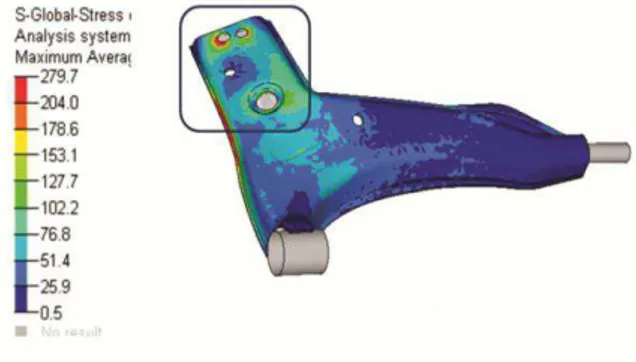
In first stage of analysis of lower arm subjected to high stresses are identified shown in fig 2. According to safer design the stresses induced in lower arm should be less than 60% of yield stress but induced stresses are higher than 60 % of yield stress and it is observed was 279.7 MPa.
Figure 2) Stress Analysis
1.2) Displacement Analysis
Displacement analysis Fig 3 shows the deflection of lower arm with respect to its constraints. It shows at what extent component will deflects from its original position. So deflection should be with in limit. Displacement observed in lower arm is 1.9 mm which should have to minimize.
Figure 3) Displacement Analysis
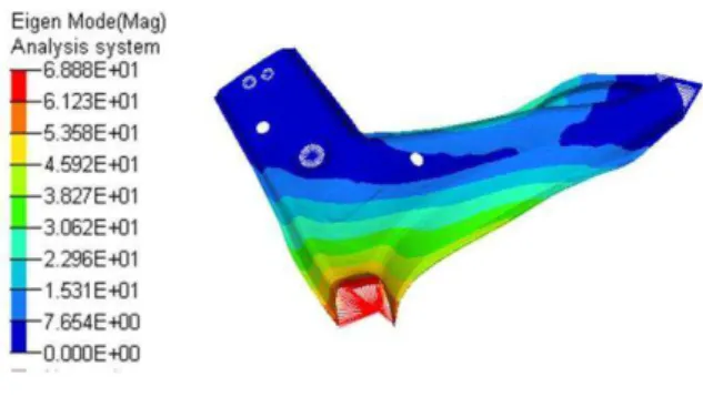
1.3) Modal Analysis
The objective of Modal Analysis is to determine the natural motions of a system, and the frequencies at which those motions occur. Modal analysis is extremely important in situations where resonance is a potential problem. (Resonance is the tendency of the system to oscillate with greater amplitude at some frequencies than at others). The results of a modal analysis in Hypermesh will be the natural frequencies and the mode shapes
The frequencies of lower arm under loading as shown in table 3, we consider one of the frequencies as reference for study. We choose 1st Frequency which is needed to increase for increasing life of lower arm.
Figure 4) Modal Analysis
Table3: Modal Frequency existing lower arm
Sr. No. Frequency
1 329
2 620
3 968.84
4 1245.7
5 1774.8
2. Topography Optimization
Topography optimization is an advanced form of shape optimization in which a design region for a given part is defined and a pattern of shape variable-based reinforcements within that region is generated. The approach in topography optimization is similar to the approach used in topology optimization, except that shape variables are used rather than density variables.
Figure 5A) Topography Optimization
Figure 5B) Bead Dimensions
Figure 5C) Bead Location Figure
Figure 5D) Overlapped Geometries
3. Second Stage Analysis
In second stage existing power arm is optimized by topography approach.
Reinforcement was done by using particular size bead generated on weak area of lower arm. Which result in reduction in stresses.
Results plotted is given as follows,
3.1) Stress Analysis
Beads results in increase in stiffness value of lower arm which results in reduction in Stresses that is 197 MPa. Fig 6 shows optimized stress result.
Figure 6) Stress Analysis
3.2) Displacement Analysis
Figure 7 shows the displacement analysis after modification of lower arm. After modification of lower arm Displacement observed is 1.3 mm which is less than previous.
Figure 7) Displacement Analysis
3.3) Modal Analysis
Figure 8) Modal Analysis
Table4: Modal Frequency of optimized lower arm
VI.
CONCLUSIONS
In this paper it has been seen that the maximum value of force transmitted by tyre to the body of vehicle through lower suspension arm. During braking and cornering lower suspension arm is subjected to high stresses because of that Failure of lower suspension arm of vehicle was reported. Plastic deformation and cracks were observed frequently during on road running of vehicle. Stress analysis was performed using finite element method. Reinforced models were proposed on the basis of result data. The finite element analysis of component leads to a reduction of physical and expensive tests. Consequently, it was not necessary for the production of several prototypes. Further corrective actions that are modifications in design will be carried on the basis of results analysis.
First stage results show higher stress effects on the component. There were two approaches to solve this problem first topology which is concerned with material density distribution in which optimization is performed on a model to create a new topology for the structure, removing any unnecessary material and second Topography which is concerned with optimization is an advanced form of shape optimization in which a design region for a given part is defined and a pattern of shape variable-based reinforcements within that region is generated.
We choose second method Topography to solve problem. We used specific size of bead to subdivide the area into a large number of separate variables whose influence on the structure is calculated and optimized over a series of iterations.
Additional bead formation in suspension arm increases its stiffness. While comparing old design stress levels are reduced also 1st mode frequency increased.
The results were shown in Table 4 for typical lower suspension arm.
Table 5: Result Table Parameter Existing
Lower arm
optimized Lower arm Stress 280 MPa 197 MPa.
Displacement 1.9 mm 1.3 mm
Frequency 329 Hz 434HZ
REFERENCES
[1] Hemin m. Mohyaldeen, “Analysis of an automobile suspension arm using the robust
design method” Thesis submitted in
fulfillment of the requirements for the award of the degree of Master of Mechanical Engineering Universiti Malaysia Pahang 2011
[2] “ Kumar, Nithin, RK, Veeresha, , Visvesvaraya “Analysis of Front Suspension Lower Control Arm of an Automobile Vehicle” Technological University, Department of Mechanical Engineering, NMAMIT, Nitte 547110,
[3] V. Veloso a, H.S. Magalhães a, G.I. Bicalho a, E.S. Palma b, a Fiat Automóveis, Rod. Fernão Dias, “Failure investigation and stress analysis of a longitudinal stringer of
an automobile chassis”, Betim, MG, Brazilb
Pontifical Catholic University of Minas Gerais (PUC Minas), Mechanical Engineering, Belo Horizonte, MG, Brazil article info: Article history: Received 3 December 2008 Accepted 9 December 2008 Available online 1 February 2009 16 (2009) 1696–1702
[4] Y. Nadota, V. Denierb “Fatigue failure of suspension arm: experimental analysis and
multiaxial criterion” aLaboratoire de
Me´canique et de Physique des, Mate´riaux, UMR CNRS No. 6617, LMPM, ENSMA, Site de Futuroscope, BP 40 109, Futuroscope Cedex 86 961, France bTechnocentre RENAULT, TCR LAB 0 45, Sce 64100, 1 rue du Golf, Guyancourt Cedex 78 288, France Received 18November 2003; accepted 11 December 2003
[5] “ J. Yamakawa , K. Watanabe “A spatial motion analysis model of tracked vehicles with torsion bar type suspension” Department of Mechanical Engineering, The
Sr. No. Frequency
1 434.6
2 699.8
3 953.4
4 1021.7
National Defense Academy, 1-10-20 Hashirimizu, Yokosuka 239-8686, Japan Available online 19 March 2004
[6] Dongchan Lee a, ChulhoYang b,n “An analytical approach for design and performance evaluation of torsion beam
rear suspension” aMetariver
echnologyCo.Ltd.,B- 801,Garden5Works,52Chungmin-
ro,Songpa-gu,Seoul138385CordellS.,Stillwater,OK740 78,USA article info Article history: Received 1November2011 Received in revised form 13 August 2012 Accepted 2 September2012 Available online9 October 2012. 63 (2013) 98–106
[7] Vinayak Kulkarni, Anil Jadhav, P. Basker, “Finite Element Analysis and Topology Optimization of Lower Arm of Double Wishbone Suspensionusing RADIOSS and
Optistruct”. International Journal of
Science and Research (IJSR) ISSN (Online): 2319-7064 Impact Factor (2012): 3.358 [8] P. Nagarjuna, k. Devaki Devi, Department
of Mechanical Engineering, G Pulla Reddy Engineering College, Kurnool, A.P., India “Design And Optimization Of Sheet Metal Control Arm For Independent Suspension
System” International Journal of
Engineering Research and Applications (IJERA) ISSN: 2248-9622 www.ijera.com Vol. 2, Issue5, September- October 2012, pp.535-539
[9] Lihui Zhao, Songlin Zheng, Jinzhi Feng and Qingquan Hong “Dynamic Structure Optimization Design of Lower Control Arm
Based on ESL” Research Journal of Applied