Stress analysis of the O-element pipe during the process
of flue gases purification
R. Nekvasil
a,∗a
Faculty of Mechanical Engineering, Brno University of Technology, Technick´a 2896/2, 616 69 Brno, Czech Republic
Received 5 September 2008; received in revised form 11 October 2008
Abstract
Equipment for flue gases purification from undesired substances is used throughout power and other types of industry. This paper deals with damaging of the O-element pipe designed to remove sulphur from the flue gases, i.e. damaging of the pipe during flue gases purification. This purification is conducted by spraying the water into the O-shaped pipe where the flue gases flow. Thus the sulphur binds itself onto the water and gets removed from the flue gas. Injection of cold water into hot flue gases, however, causes high stress on the inside of the pipe, which can gradually damage the O-element pipe. In this paper initial injection of water into hot pipe all the way to stabilization of temperature fields will be analyzed and the most dangerous places which shall be considered for fatigue will be determined.
c
2008 University of West Bohemia in Pilsen. All rights reserved.
Keywords:FSI analysis, O-element, pipe, stream mixing, head field, fatigue
1. Introduction
Removing undesired harmful substances from flue gases is a very important industrial process that is constantly being subject to research activities in order to find out new methods of flue gases purification. This is mainly caused by strict legislation on emission limits in developed countries. Among some of the undesired substances are sulphur dioxide, carbon monoxide, dioxins, solid substances, heavy metals, etc.
The Institute of Environmental and Process Engineering at Brno Technical University ex-amined scrubbing of flue gases when sulphur was removed and thus the content of sulphur dioxide in the flue gases was lowered [1, 6]. This experiment was carried out in O-element; water was injected into the flowing flue gas and the sulphur bounded itself to the water and created sulphide. Since there was a temperature shock due to cooling of hot flue gas by cold water while carrying out this experiment, these pipes underwent a series of thermo-hydraulic and consequently stress analyses in order to determine to which extent its lifetime is lowered by these effects [3].
2. Analysis of the experiment
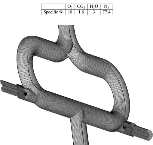
The O-element is made of steel 15 128 (11CrMo9-10). Material properties are given in tab. 1. The size of the pipe is 100x4. An input pipe is divided into two U-shaped pipes and there is a pipe of 69x3 with jets tangentially attached to the lower part. Through jets the water is injected into the flow of the flue gases. Two pipes merge back together at the concurrence
Table 1. Material properties of steel 15 128 (11CrMo9-10)
T [◦C] Re[MPa] Rm[MPa] E[MPa]
20 358.7 505.6 213 300
100 336.4 471.0 209 000
200 308.9 459.1 202 100
Fig. 1. Type of O-element used
of the two flows. Geometric disposition of the O-element is displayed in fig. 1. Model was slightly simplified for the purposes of numeric simulations in a sense that flanged joints were not considered.
During the flue gases purification experiments the ideal ratio of flue gases flow rate to in-jected water flow was searched. Flue gas flow rate changed in the range from 700 to 1 000 m3
N/h, water flow rate varied in the range from 0.68 to 2.15 m3/h [6]. From all analyzed variants one was chosen for numerical simulation. It corresponded to a low flue gases flow rate and the largest volume of injected water. Precisely, the value of flue gases flow rate equalled to 800 m3
N/h and water flow rate equalled to 2.15 m 3
/h. Temperature of flue gases entering the O-element equals to200◦C, temperature of water entering nozzles equals to20◦C. Flue gases chemical composition is given in the tab. 2 [6].
Table 2. Flue gases chemical composition
O2 CO2 H2O N2
Specific % 18 1.6 3 77.4
Fig. 2. Computational model of O-element for numerical analysis
of the medium was refined at the line between medium and pipe, which makes up the boundary layer. Symmetry of the model was used in order to reduce the amount of nodes and elements. Input and output pipes were modeled extendedly so that there are no interferences of important areas with boundary conditions. It also helped in developing sufficient flowing. Jets were distinctly refined (both the fluid and solid model, see fig. 2) since these are the places where liquid medium meets the gas one or cool meets the hot.
3. Procedure of Analysis
As to the calculations that were done, there was not a full version of the software available, thus we transferred the data manually using CFX-Solver Manager. This was done by means of the *.res file for concrete time and for the selected volumes and surfaces. Since the temperatures in the volume of material are the most important ones, we exported temperatures of all node points using 3D Thermal elements (70) and pressure on inner pipe wall using 2D Stress elements (154). Both files were exported into a cdb format which is compatible with ANSYS program. Files contain information about coordinates, temperatures and pressures for the nodes selected. Multiple file analysis (the so called Multifield analysis) was used for determining distribu-tion of stress in the pipe material. This type of analysis implements several files into structural one and requires that the calculation model is in cdb format (made up of elements and nodes only, not of geometry) and boundary conditions are considered as new meshes. These new meshes have to merge with the calculation mesh so that the transfer of data from one mesh to another is possible (i.e. from thermal mesh to the structural one). Other boundary conditions such as constraints and forces are entered on node groups which were already created upon making up of the calculation model. Since all the boundary conditions are entered, it is neces-sary to define mutual relations between individual files, i.e. to define main model and following external files (data on temperatures and pressures). It is also necessary to define the procedure of the calculation which means that the temperature deformations are to be calculated first, then pressure deformations and only then come other boundary conditions. All this data has to be entered into one final file usable for following experiments.
4. Analysis of flow and thermal fields distribution
Models for two-phase streaming were to be used in the simulations. For the cases of dispersion (spraying) of fluid medium in gas medium it is convenient to use particles trajectory model (Euler-Lagrange principle) [4, 10]. It describes initial phase as a continuum by means of av-eraged Navier-Stokes equations. In a secondary phase a flying trajectory is traced for drops which can transmit momentum, mass and energy from the initial phase. The basic condition of the method sounds that secondary phase must occupy very small volume fragment, this condi-tion is satisfied in the O-element.
K-εmodel was used for turbulence [9]. Momentum transfer was realized by means of Drag Coefficient. Gas medium was entered as continuum, fluid medium was entered as dispersion with known drop size 10µm [6]. Particle Model was used for interphase transmission. Heat transfer between flue gases and drops was described by means of Nusselt number or more precisely Ranz-Marshall correlation. Mass transfer was described by constant evaporative ratio, which was taken from the work [6]. Initiation was entered according to operating conditions of flowing fluids.
Boundary conditions were presented by inlet of water and flue gases and outlet of flue gases. Initiation was entered according to inlet conditions of flue gases. To achieve higher stability of calculation, flue gases were taken as incompressible.
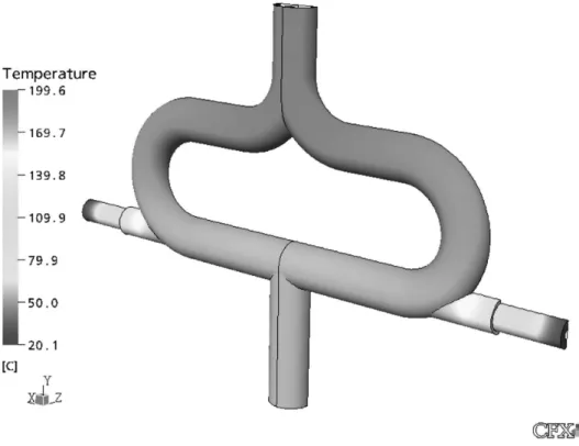
In the beginning of the process the pipe is heated to the temperature of flue gases (200◦C), when the purification process starts, cold medium (20◦C) is injected. Surface layers of mate-rial experience shock changes and development of additional stresses due to different thermal expansion. During several tens of seconds thermal fields distribution is stabilized. The most significant thermal influence occurs in nozzles, precisely in sharp edges above nozzles. Based on thermal-hydraulic analysis there were chosen time moments when thermal fields distribution influences principally caused stresses.
It is obvious from the results that pressure drops take place in the place where both streams collide, moreover streaming changes its direction rapidly. Temperature of flue gases immedi-ately after water injection is markedly lower. Volume content of fluid compared to that of flue gases is very low. Since drops flow in the same direction with flue gases, achieved results are better compared to other ways of flue gases purification (e.g. Venturi scrubber), where fluid is injected upright to the flow of flue gases [2, 7, 8].
Fig. 3. Thermal field distribution
5. O-element stresses
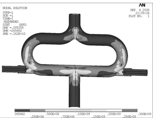
Fig. 4. Stress distribution in O-element (stress intensity)
of value cca 200 MPa appear in these zones. During cooling the amplitude is about several tens of MPa. The most critical zone is the one where a pipe for flue gases outlet is connected. Here both flows meet each other and drain into one pipe. Connection of pipes with same sizes is designed not favourably, this causes high values of stresses, locally up to 300 MPa, and near edges around 200 MPa. During cooling the amplitude is about several tens of MPa.
6. Damage of separate zones
On the basis of performed analyses for particular time moments stresses changes were de-termined for separate areas of the O-element during thermal fields setting. Those are princi-pal for damage cumulation determination. There were chosen zones with maximum values of stresses, for these zones damage cumulation was determined. Fig. 4 shows clearly that signif-icant stresses appear in the place where pipes for flue gases outlet is connected, below nozzles and in the area where main piping is divided into two flows. It is possible to say that these are the places of essential geometrical changes.
Fig. 5. The most loaded zones
Fig. 6. W¨ohler’s curve for high-cycle fatigue
were used. The zones chosen earlier were evaluated; cyclic load for them was derived from the process of streams setting. Each zone was represented by the most loaded points. Resultant cumulation of damage is shown in the tab. 3 and corresponds to the load from one cycle.
Table 3. Table of cumulation for separate zones
7. Conclusion
Flue gases purification is interesting not only from chemical processes point of view, but also from mass change point of view as well as from thermal loading point of view. To solve the problem there was used the combination of computational methods so called FSI (Fluid Struc-ture Interaction). The most demanding stage was two-phase flow simulation which takes place when cold water is injected into hot flue gases. It was very important to input correct values of computational model and different parameters.
CFD results showed that heat exchange between flow gases and water drops took place al-most immediately. It was also found out that this way of flue gases purification does not involve so high values of pressure drops and is more efficient compared to other types of purification. Determined thermal field distribution made it possible to find out stress state. This was done in ANSYS software for particular time moments. Stress changes were analyzed and the most loaded zones were determined. They were analyzed from high-cycle fatigue point of view fur-ther on.
Components of stress tensor and their changes in particular zones were used for high-cycle fatigue analysis. The results showed that damage cumulation in all zones is neglectable. It is possible to state that for such loading conditions the O-element will endure unlimited number of injections of water into flowing hot flue gases.
Acknowledgement
We gratefully acknowledge financial support of the Ministry of education, youth and sports of the Czech Republic within the framework of research plan No. MSM 0021630502 “Waste and Biomass Utilization focused on Environment Protection and Energy Generation”.
References
[1] J. Buchta, M. Filip, L. B´ebar, P. Stehl´ık, M. ˇSarlej, New design in off-gas clearing systems sup-ported by experimental and computational approach, Chemical Engineering Transactions 7 (2005) 375–380.
[2] G. F. Hewit, Heat exchanger design handbook, Begell House, Inc., New York, 1998.
[3] S. Chapuliot, C. Gourdin, T. Payen, J. P. Magnaud, A. Monavon, Hydro-thermal-mechanical anal-ysis of thermal fatigue in a mixing tee, Proceedings of Fatigue of reactor components, Proceedings on CD ROM, Seville, 2004.
[4] C. Kleinstreuer, Two-phase flow, Theory and applications, New York, London, Taylor & Francis, 2003.
[5] T. H. G. Megson, Structural and stress analysis, Oxford, 2000.
[6] M. Piskovsk´y, Modelling of equipment used in waste combustion and off-gas cleaning systems, Ph.D thesis, Brno university of technology, Brno, 2008.
[7] M. Piskovsk´y, J. H´ajek, P. Stehl´ık, Computational fluid dynamics simulation of venturi wet scrub-ber, Proceedings of the 17thInternational Congress of Chemical and Process Engineering CHISA 2006, 9thConference on Process Integration, Modeling and Optimisation for Energy Saving and Pollution Reduction PRES 2006, Proceedings on CD ROM, Prague, 2006.
[8] R. A. Pulley, Modeling the performance of venture scrubbers, Chemical Engineering Journal 67 (1) (1997) 9–18.
[9] T. H. Shih, W. W. Liou, A. Shabbir, Z. Yang, J. Zhu, A new k-εeddy-viscosity model for high
Reynolds number turbulent flow — model development and validation, Computers Fluid 24 (3) (1995) 227–238.
![Table 1. Material properties of steel 15 128 (11CrMo9-10) T [ ◦ C] R e [MPa] R m [MPa] E [MPa]](https://thumb-eu.123doks.com/thumbv2/123dok_br/16362031.190321/2.748.109.643.116.672/table-material-properties-steel-crmo-mpa-mpa-mpa.webp)