Qualitative evaluation in photoelastic experimental
models of the force system generated by T-springs
placed in the center of the interbracket space with
pre-activations advocated by Burstone
Objective: To evaluate the force system generated by T-springs placed in the center of the
interbracket space using the pre-activations advocated by Burstone. Methods: Photoelastic
models were used to assess T-springs fabricated with 0.017x0.025-in rectangular titanium-molybdenum alloy wire (TMA), centrally positioned, with 6.0 mm activation, 3 mm activa-tion, and in neutral position. To ensure reliable results, tests were repeated on three photoelas-tic models equally duplicated and fabricated by the same operator. An interbracket distance of 27.0 mm was used. For a better understanding of the results, the fringes were viewed in a polariscope, then photographed and qualitatively analyzed. Results: Through qualitative analysis of the fringe order in the photoelastic model it was noted that both the retraction and anchorage ends displayed force system symmetry across the full extent of the root.
Abstract
Keywords: Orthodontic space closure. Biomechanics.
IntROductIOn
When orthodontic treatment is administered with the aid of a detailed diagnosis premolar ex-traction is sometimes performed, which requires that orthodontists have an accurate knowledge not only of biomechanics for the closure of remaining spaces but of histological, anatomical and physi-ological principles.24 Space closure may occur by
distalization of anterior teeth, mesial movement of the posterior segment or a combination of both.4,21
At this stage it is important that health profes-sionals choose the device to be used in accordance with the type of anchorage needed, noting the force system being released, so as to ensure ad-equate movement control without damaging the structures adjacent to the teeth.1-7,12,13,15,16,21,27,28,30
Luiz Guilherme Martins Maia*, Vanderlei Luiz Gomes**, Ary dos Santos-Pinto***, André da Costa Monini****, Luiz Gonzaga Gandini-Jr*****
* Professor of Dentistry, Tiradentes University, Sergipe. Specialist in Orthodontics, – EAP/APCD - UNESP – Araraquara. MSc in Dental Sciences, Orthodon-tics, Araraquara Dental School - UNESP.
** Assistant Professor of Orthodontics, Department of Child Clinic, School of Dentistry, Araraquara - UNESP. Post-doctorate and Assistant Associate Clinical Professor, Department of Orthodontics, Baylor College Of Dentistry-Dallas-TX.
*** Head Professor, Removable Prosthodontics and Dental Materials, School of Dentistry, Federal University of Uberlândia. MSc and PhD in Dentistry, USP - Ribeirão Preto - São Paulo.
**** Specialist and Master in Orthodontics, Faculty of Dentistry of Araraquara / UNESP. Student in the Postgraduate (PhD), UNESP / FOAr.
A
B C
B
D
c
Considering this force system and the princi-ples of the segmented arch technique,3 Burstone,6
in 1982, envisioned the T-spring, fabricated with titanium-molybdenum wire, cross-section size 0.018x0.025-in or 0.017x0.025-in, which would allow clinicians to work with enhanced predictabil-ity. Arguably, the force system thus released would be closely related to the amount of activation and incorporation of pre-activation bends,6 thereby
making it possible to control the center of rotation of the teeth with a greater degree of accuracy.
In a unique manner, T-springs provide low force magnitude in high activation quantities.6,7,21,25-28,30
This is due to the type of alloy used and the sub-stantial quantity of wire incorporated into its design. Clinically, this is very positive since the amount of activation is considerable while the loss of force is relatively low when compared to other space closure devices. Therefore, this device con-tinues to provide satisfactory levels of moment/ force (M/F) and load/deflection (L/D) ratios.
Scientific literature on studies of mechani-cal testing and clinimechani-cal research shows that the T-spring advocated by Burstone6 delivers an
ef-ficient force system for controlled tooth move-ment, but little has been studied on this device using the photoelastic method.18 This method is
the qualitative observation and / or quantitative areas of tension in resin models that are optically visualized by order of the fringes, when subjected to tension.2,8,9,10,11,14,16,19,23,29
Thus, the purpose of this study is to evalu-ate, in experimental photoelastic model, the sys-tem of force generated by Burstone´s T-spring, centered in interbracket space, seeking, through qualitative analysis, support to complement the existing research.
MAtERIAL And MEtHOdS
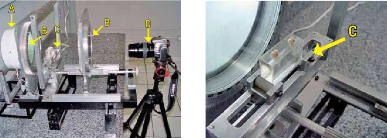
The photoelastic experimental analysis technique was used as it transforms internal mechanical forces into visible light patterns that indicate the location and magnitude of stress. It is based on the principle that when a beam of polarized light passes through a bi-refringent material differences in the speed of the beams can be observed with a polarizing filter. The equipment used for viewing the photoelastic effect was a circular polariscope (Fig 1) consisting of: A lighting system (Fig 1A), a pair of polarizers (Fig 1B), a support to sustain the photoelastic model (Fig 1C) to be observed, and a camera to acquire images and analyze results19,23 (Fig 1D).
Initially, tests were performed on 5 experi-mental pilot models in order to determine proper methodology research, materials to be used, num-ber of repetitions needed, model fabrication tech-nique, reading technique and researcher calibra-tion to ensure result accuracy.23
The pilot study and literature review enabled the definition of criteria for obtaining the ideal materials and models in order to conduct the pho-toelastic tests, namely:
1. Fringe overlap was avoided. This phenomenon occurs when multi-rooted teeth are used, or else when the distance between the teeth is too small, causing fringes to overlap when forces are applied.
2. Materials were used that quickly return to their initial condition when force delivery ceases, and which do not exhibit residual stresses be-fore and after such forcesaresuspended.23
3. Ideally, the material used in fabricating the model should provide a high optical constant, low elasticity modulus, high optical and me-chanical resistance, high strain and flexibility ratio. Moreover, it should be readily available, easy to machine, transparent, free from stains and residual stresses, and affordable.23
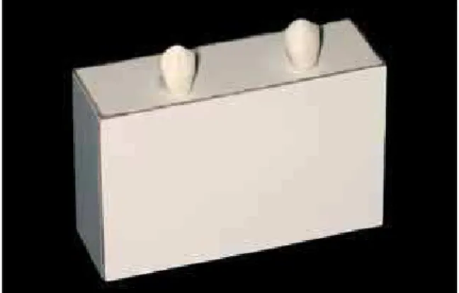
After fabrication of the pilot models three photoelastic models were made with Formica based on a master model, measuring 60.0 mm in length, 40.0 mm in height and 20.0 mm thickness. To simulate and reproduce the position of canines in the photoelastic model two canine crowns were positioned and bonded with Loctite® universal
in-stant adhesive (Super Bonder) at a distance that would allow the brackets to be positioned at 27.0 mm in future (Fig 2).
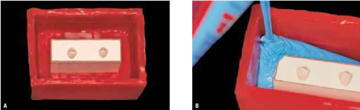
A utility wax box was made with the following dimensions: 120.0 mm wide, 140.0 mm long and 90.0 mm in height so that the master model could be positioned, and subsequently ASB-10 blue
sili-cone rubber manufactured by Polipox Indústria
e Comércio Ltda., São Paulo, Brazil, was poured and properly handled with a rubber catalyst
manufactured by the same company (Fig 3) ac-cording to manufacturer’s specifications, thus ob-taining a negative mold. At this stage, other teeth were positioned in their respective sites while carefully preventing contamination by moisture and/or grease on the root surfaces of the canines and on the silicone. At this point, photoelastic ep-oxy resin was manipulated and used as inlay (Fig 4) to obtain the definitive photoelastic model.
In manipulating photoelastic resin, compo-nent A was gradually blended (20.0 ml) with component B (10.0 ml) (Figs 5A and 5B) in a glass container scaled in milliliters. The two components were placed in a Becker and care-fully manipulated for 10 minutes to prevent the incorporation of air bubbles. The mixture was then placed in an oven at a constant tempera-ture of 25° C for 24 hours to complete the set-ting reaction. After this time period the model was removed from the mold. At this stage one needs to check the optical conditions of the photoelastic model in a polariscope. If the mod-el does not display satisfactory optical proper-ties,23 which may interfere with the analysis,
one should discard it and repeat the same steps over again until an ideal model is produced.
Once the photoelastic models had been de-fined and the insertion of a T-spring was in order, the authors chose to use crossed tubes. To this
A
A A
B
B B
end, a vertical slot was drilled on the crowns of the teeth where the tubes were fitted and bonded with acrylic resin (Fig 6).
For each model, a T-spring was used, made with titanium-molybdenum wire (TMA), with a cross-section of 0.017x0.025-in. In order to maintain
the T-spring standard defined by Burstone6 when
he first fabricated it, a template was made with the following measurements: 10.0 mm in length and 7.0 mm in height. At this point, pre-activa-tion bends were incorporated into the spring, fol-lowing the standard set by Burstone6 (Fig 7).
After checking the T-springs in neutral posi-tion, they were inserted into the horizontal slots
of the crossed tubes, centered at an interbracket distance of 27.0 mm and evaluated under three different activations: 6.0 mm, 3.0 mm and in neu-tral position (0.0 mm).
The tests were performed in the laboratory of Mechanical Engineering, Federal University of Uberlândia-MG (Department of Physics). Evalu-ation was conducted with a refraction polariscope and photographed with a digital camera.
After application of stress resulting from the installation and activation of the T-spring, read-ing of the frread-inge order was performed through the violet and blue interface as far as the distal, me-sial and apical surface of each tooth. This distance
FIGURE 3 - ASB-10 Blue silicone rubber, poured after proper manipulation to obtain negative mold.
FIGURE 5 - Photoelastic resin: A) Component “A” Epoxy resin, flexible CMR-201 and B) Component “B” Flexible CME-252 Hardener.
10 10 11 f e d c b a
a` b` c` d` e` f` 9 87 65 43 21 12 34 56 7 89
x
y
A B
would be used as reference to produce the analy-sis charts. Between the lowest stress level and the highest stress level the following colors are formed: black, yellow, red, blue, yellow, red, green, yellow, red, green (Fig 8).
RESuLtS And dIScuSSIOn
Orthodontic literature has shown that several techniques are currently used for assessing the force system generated by the T-spring.6,7,12,15,17,21,25,27,28,30
On the one hand, mechanical tests4,6,7,15,21,25,27,28,30
and the finite element17 have proven that the
T-spring can provide predictable results, thereby assuring its safe clinical use. On the other hand,
clinical research12 has demonstrated such
efficien-cy through adequate results with no damage to adjacent tissues.
In this study, evaluation of the force system generated by the T-spring was performed accord-ing to the pre-activations suggested by Burstone,6
with the T-spring centered in the interbracket space and using the photoelastic experimental method for qualitative analysis of pressure and stress areas.1,2,8,9,10,11,14,16,19,23,29 This method is
widely used in dentistry in the research of bioma-terials, especially in the areas of prosthodontics, dental implants and occlusion, and consists of a method for direct visualization, in photoelastic
FIGURE 6 - A) Photoelastic model with crossed tubes in position. B) Close up of crossed tubes inserted to the crowns of acrylic teeth.
A
13
23
A
D
M
D
AMDeAMDd AMDcAMDb AMDa AMDaAMDb AMDcAMDd AMDe
models, of the effects occurring in these materials when subjected to forces and/or stresses.2,8,9,10,19,23
Just as importantly, this method is also used in dentistry in the fields of surgery11 and
periodon-tics.14 It has been used in orthodontics since
193530 to assess the types of tooth movement that
take place when forces are delivered from differ-ent points to the teeth. Since then, much research has been conducted in all dental specialties using photoelasticity. As a result, this evaluation meth-od has been increasingly refined. However, stud-ies often fail to clarify their methodologstud-ies. This tends to complicate the work of researchers, who are often unaware of such experiments and are therefore led to withdraw from them.
In this study, the results were obtained through qualitative reading of the fringes formed in the photoelastic models with the use of T-springs, centrally positioned and under the pre-activations
recommended by Burstone6. Each spring was
ana-lyzed under three different activations, i.e., the first in neutral position, the second with a 3.0 mm activation, and the last with a 6 mm activation.6
Interpretations were evaluated descriptively and depicted in charts. Charts were made for the mesial, apical and distal root surfaces and analyzed separately, one at a time (Fig 9). The order of the fringes formed in the photoelastic model resulting from the stress caused by the activations was rep-resented in a Cartesian axis showing a yellow line (neutral position), a blue line (3.0 mm activation) and a red line (6.0 mm activation).
Figure 10 shows that in the absence of a T-spring no photoelastic fringes are formed. The point located at the vertex of Figure 11 depicts a stress-free photoelastic model where the fringe order is 0.0 across the entire root surface of both teeth.
Upon insertion of Burstone’s T-spring in neu-tral position (Fig 12), a fringe order with less than 0.5 was formed across the root surface. This means that in this qualitative analysis, although stress was equally distributed from the cervical region
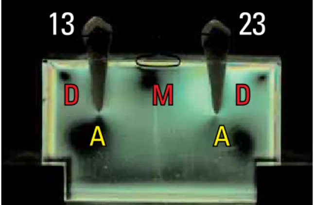
FIGURE 9 - Nomenclature suggested for reading and interpreting fringe orders on photoelastic model. 13 - Left tooth – observer’s view. 23 - Right tooth – observer’s view. D - Distal surface of teeth. M - Mesial surface of teeth. A - Apical surface of teeth.
FIGURE 10 - In the absence of T-spring, fringe order of 0.0 observed through the polariscope, indicating absence of forces and moments.
FIGURE 11 - The green dot at the vertex of the graph represents the fringe order zero.
Fringe order
Tooth 13 Tooth 23
FIGURE 12 - Insertion of T-spring in neutral position generated fringe order very close to zero over entire root surface.
FIGURE 13 - View of photoelastic model with 3.0 mm activation.
FIGURE 14 - 6.0 mm T-spring activation.
down to the root apex, apparently only a small amount of energy or a very low force magnitude was applied to these teeth (Figs 15, 16 and 17).
When the T-spring was given a 3.0 mm acti-vation, stress was formed symmetrically with a fringe order of 1.5 in the cervical-most region of
the mesial surface (Figs 13 and 15). In this same activation, the fringe order on the apical surface (Fig 16) and on the distal surface of the roots (Fig 17) was smaller than 0.5, showing that the stress generated in these regions is lower than the stress formed on the cervical region of the mesial surface, demonstrating that the onset of movement had characteristics indicative of con-trolled inclination.
The 6.0 mm activation (Fig 14) showed fring-es across the entire mfring-esial surface that were also symmetrical for both teeth. There was a fringe order of nearly 0.5 on the apical surface of tooth 13 and lower for tooth 23, suggesting a slight asymmetry in Burstone’s T-spring or an asymme-try in its activation, or even an asymmeasymme-try during the fabrication process. This difference, however, was barely perceptible, indicating that this acti-vation is likely to perform its expected functions, such as space closure through controlled inclina-tion. The fringe order in the mesial region of the root located closest to the cervical third was 2.5, suggesting that stress concentration is higher in this region. On the distal surface of the roots the fringe order was 0.0, indicating that no signifi-cant stress occurs on this surface.
Scientific literature shows that when a T-spring is given maximum activation it promotes a controlled inclination movement and the great-er its deactivation, the greatgreat-er the M/F ratio in the tooth, bodily movement and root correction.
Burstone and Pryputniewicz5 asserted that in
an-terior teeth the center of resistance is found at 1/3 of the space between the alveolar crest and tooth apex. They also stated that if a controlled inclination movement is to be achieved the de-vice should release an M/F ratio of 7.1/11, and in order to generate translational movements and root correction this ratio should be, respectively, 9.9/1 and 11.4/1.
In 1984, Smith & Burstone26 advanced that
Mf13 Me13 Md13 Mc13 Mb13 Ma13 Ma23 Mb23 Mc23 Md23 Me23 Mf23
Af13 Ae13 Ad13 Ac13 Ab13 Aa13 Aa23 Ab23 Ac23 Ad23 Ae23 Af23
Df13 De13 Dd13 Dc13 Db13 Da13 Da23 Db23 Dc23 Dd23 De23 Df23
movement, and finally root correction. At no time during this study was the formation of a fringe greater than 0.5 ever noted in the distal apical region of the tooth roots, which in this case would have demonstrated a tendency to-wards uncontrolled inclination movement.
Asymmetries were negligible, with a fringe or-der below 0.5. Hypothetically, the emergence of these asymmetries may have been due to some interference in the central position of the T-spring, or else some asymmetry during fabrication in the final design of the T-spring.
Another important finding in the tests using photoelastic models was the symmetrical forma-tion of photoelastic fringes under all activaforma-tions. In comparing the results depicted in the charts, similar values could be found for both teeth (13 and 23) in the distal, mesial and apical regions, suggesting that, regardless of the T-spring acti-vation, when the T-spring is centered in the in-terbracket space, the M/F and L/D ratios will be identical for both the active unit (retraction) and the reactive unit (anchorage). This force system released between the segments of the active and reactive units was also observed in studies using mechanical tests4,7,24,27,28 i.e., moments of equal
magnitude and in opposite directions are gener-ated by a symmetrical V-shaped pre-activation bend. Moreover, when this end is inserted in the bracket slots an activation moment will be
released. In 2006, Thiesen et al30 reported that
the greater the pre-activation bend, the greater the M/F ratio.
The use of a T-spring to close spaces is ef-ficient in the opinion of many researchers. Hence the orthodontic community’s interest in researching this type of orthodontic de-vice from different angles, such as which wire cross-section to use, the type of alloy, moment/ force and load/deflection rations, the incor-poration or not of helices into these springs, and height and length increases in its de-sign.6,7,12,15,20,21,22,25,27,28,30
FIGURE 15 - Representation of the mesial surface.
FIGURE 16 - Representation of the apical surface.
FIGURE 17 - Representation of the distal surface.
Fringe order on mesial surface
Fringe order on apical surface
Fringe order on distal surface
root movements the ratio should be 10/1 and 12/1, respectively. In this study, T-spring deac-tivation resulted in a loss of energy in the cervi-cal mesial region and an increase in energy in the distal apical region. A change was observed from controlled inclination movement to bodily
cOncLuSIOnS
After implementing the experimental photo-elastic method for qualitative analysis of the force system delivered by centered T-springs fabricated with 0.017x0.025-in TMA wire, the following conclusions could be drawn:
1. In neutral position, the T-spring displayed a very low fringe order across the entire root surface.
2. With a 3.0 mm activation, the fringe order ex-hibited a tendency towards controlled inclina-tion movement.
3. At 6.0 mm activation, the concentration of en-ergy or force was clearly higher.
4. The fringe order did not show any character-istics indicative of uncontrolled inclination movement under any of the activations.
1. Baeten LR. Canine retraction: a photoelastic study. Am J Orthod. 1975 Jan;67(1):11-23.
2. Burns DR, Unger JW, Elswick RK, Giglio JA. Prospective clinical evalution of mandibular implant overdentures: Part II - patient satisfaction and preference. J Prosthet Dent. 1995 Apr;73(4):364-9.
3. Burstone CJ. Rationale of the segmented arch. Am J Orthod. 1962 Nov;48(11):805-22.
4. Burstone CJ, Koenig HA. Optimizing anterior and canine retraction. Am J Orthod. 1976 Jul;70(1):1-19.
5. Burstone CJ, Pryputniewicz RJ. Holographic determination of centers of rotation produced by orthodontic forces. Am J Orthod. 1980 Apr;77(4):396-409.
6. Burstone CJ. The segmented arch approach to space closure. Am J Orthod. 1982 Nov;82(5):361-78.
7. Kuhlberg AJ, Burstone CJ. T loop position and anchorage control. Am J Orthod Dentofacial Orthop. 1997
Jul;112(1):12-8.
REfEREncES
8. Caputo AA, Chaconas SJ, Hayashi RK. Photoelastic visualization of orthodontic forces during canine retraction. Am J Orthod. 1974 Mar;65(3):250-9.
9. Caputo AA, Standlee JP. Biomechanics in clinical dentistry. Chicago: Quintessence; 1987. p. 13-28.
10. Chaconas SJ, Caputo AA, Miyashita K. Force distribution comparisons of various retraction archwires. Angle Orthod. 1989 May;59(1):25-30.
11. Clelland NL, Gilat A, McGlumphy EA, Brantley WA. A photoelastic and strain gauge analysis of angled abutments for an implant system. Int J Oral Maxillofac Implants. 1993; 8(5):541-8.
12. Fuziy A. Estudo cefalométrico comparativo de três formas de retração parcial dos caninos [dissertação]. Araraquara (SP):UNESP;1997.
23. Oliveira EJ. Material e técnica para análise fotoelástica da distribuição de tensões produzidas por implantes odontológicos [dissertação]. Uberlândia (MG): Universidade Federal de Uberlândia; 2003.
24. Shimizu RH. Fechamento de espaços após exodontias de primeiros pré-molares [dissertação]. Araraquara (SP): UNESP; 1995.
25. Shimizu R H. Estudo dos sistemas de forças gerados pelas alças ortodônticas para fechamento de espaços [tese]. Araraquara (SP): UNESP; 1999.
26. Smith RJ, Burstone CJ. Mechanics of tooth movement. Am J Orthod. 1984 Apr;85(4):295-307.
27. Souza RS, Santos-Pinto A, Shimizu RI, Sakima MT, Gandini Júnior LG. Avaliação do sistema de forças gerado pela alça T de retração, pré-ativada segundo o padrão UNESP-Araraquara. Rev Dental Press Ortod Ortop Facial. 2003 set-out; 8(5):113-22.
28. Souza RS, Shimizu RI, Sakima MT, Santos-Pinto A, Gandini Júnior LG. Avaliação do sistema de forças gerado pela alça T de retração pré-ativada segundo o padrão Marcotte. JBO: J Bras Orthod Ortop Facial. 2005;10(55):50-8.
29. Tachibana K, Kuroe T, Tanino Y, Satoh N, Ohata N, Sano H, et al. Effects of incremental curing on contraction stresses associated with various resin composite buildups. Quintessence Int. 2004 Apr;35(4):299-306.
30. Thiesen G, Rego MVNN, Menezes LM, Shimizu RH. A
utilização de diferentes conigurações de molas T para
obtenção de sistemas de forças otimizados. Rev Dental Press Ortod Ortop Facial. 2006 set-out;11(5):57-77.
Submitted: October 2007
Revised and accepted: November 2009
14. Glickman I, Roeber FW, Brion M, Pameijer JHN. Photoelastic analysis of internal stresses in the periodontium created by occlusal forces. J Periodontol. 1970 Jan;41(1):30-5. 15. Lanes MA, Fuchs G, Thiesen G, Menezes L. Comparação
entre forças liberadas por alças de fechamento de espaço, com diferentes comprimentos, utilizadas em Ortodontia. Ortodon Gaúch. 2004 jul-dez;8(2):11-7.
16. Lehman ML, Meyer ML. Relationship of dental caries and stress: Concentrations in teeth as revealed by photoelastic test. J Dent Res. 1966 Dec;45(6):1707-14.
17. Lotti RS, Mazzieiro ET, Landre Júnior J. A inluência
do posicionamento da alça T segmentada durante o movimento de retração inicial. Uma avaliação pelo método
dos elementos initos. Rev Dental Press Ortod Ortop Facial.
2006 maio-jun;11(3):41-54.
18. Maia LGM, Gomes VL, Santos-Pinto A, Júnior IL, Gandini Júnior LG. Estudo qualitativo fotoelástico do sistema de forças gerado pela mola “T” de retração com diferentes pré-ativações. Dental Press J Orthod. 2010;15(4):103-16. 19. Mahler DB, Peyton FA. Photoelasticity as a research
technique for analysis stresses in dental structures. J Dent Res. 1955 Dec;34(6):831-8.
20. Manhartsberger C, Morton JY, Burstone CJ. Space closure in adult patients using the segmented arch technique. Angle Orthod. 1989;59(3):205-10.
21. Marcotte MR. Biomecânica em Ortodontia. São Paulo: Ed. Santos; 1993.
22. Mendes AM, Bággio PE, Bolognese AM. Fechamento de espaços. Rev Soc Paul Ortod. 1992;2:11-9.
contact address