Design of Miniature Patch Antenna Around the Frequency
3.5 GHz for WIMAX Technology
Adnane-Latif 1
1
Laboratory of Information Technology and Modeling, Cadi Ayyad University, National School of Applied Sciences, Marrakesh, Morocco
Abstract
This work aims to study a miniature rectangular patch antenna
λ / 8 fed by coaxial probe with the transmission line method (TLM). The design and simulation of this antenna is around the frequency of 3.5GHz, for WIMAX technology. The results obtained (input impedance, reflection coefficient, VSWR and bandwidth) are given by the program in the software MATLAB.
Keywords: Patch antenna, Wireless Communications, Wireless Metropolitain Area Network, Wimax, Design.
1. Introduction
In the first part, this paper deals the modeling of the rectangular patch antenna λ / 8 fed by coaxial probe with the TLM model.
The second part of this paper is devoted to the simulation of this antenna in the frequency of 3.5 GHz for WIMAX applications, to determine the parameters necessary for the antenna’s design.
The key parameters of these simulations are: the input impedance, the resonance frequency, the reflection coefficient and the standing wave ratio (VSWR), with and without compensation of inductif effect caused by the coaxial probe inductance used to feed the patch antenna
λ / 8.
2. Modeling of Patch Antenna
λ
/ 8
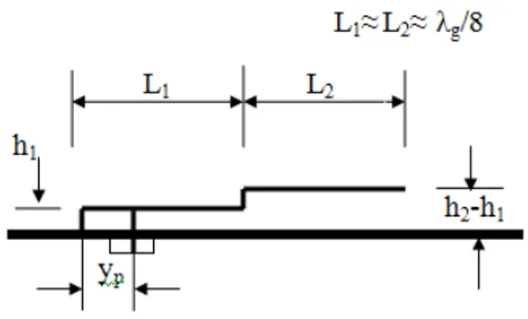
Either, the patch antenna λ / 8 represented in the below figure:
Fig 1 Structure of the patch antenna λ / 8
Its equivalent circuit with the TLM method is shown in the figure 2:
Fig 2 Equivalent circuit of the patch antenna λ / 8 with the TLM method
Zin : Impédance d’entrée de l’antenne.
Xf : Réactance inductive
Y01: Characteristic admittance of the line.
Y02: Characteristic admittance of the line L2 (L1 = L2).
Z1: Impedance of the antenna without that of the coaxial probe.
Zin: Input impedance of the antenna.
3. Design of the Patch Antenna
λ
/ 8
3.1 Resonant Frequency and Input Impedance
A design around the frequency of 3.5 GHz for industrial applications in telecommunications namely WMAX, the dimensions of the patch are: The substrate dielectric permittivity ε
r=2.1, the length of the inferior patch
is L1 = 14 mm and the upper patch is L2 = 14.5 mm. The widths of the patches W1et W2 are equal and worth 18.7mm. The height of the inferior patch is h1 = 2.78 mm and that of the upper patch h2 = 5.4mm.
The coaxial probe position from the edge of the short circuit is x = 2.2 mm. This gives a resistive part of the input impedance of 49.98 Ω in the resonant frequency 3,5 GHz. The coaxial probe radius is 0.32 mm; the inductance in the resonant frequency is 25.14 nH.
The figure 3 shows the real part of the input impedance, the curve peaks indicates the input resistance of the antenna.
Fig 3 Input resistance of the patch antenna λ / 8 as a function of the frequency.
I can conclude from the figure 3, that resonance frequencies of the patch near 3.5 GHz, 10.4 GHz and 17.2GHz respectively corresponding to the lengths of the patch L1eff = λ / 8, L1eff = 3λ / 8 and L1eff=5λ/8 (L1eff is the effective length of the patch) . The fundamental mode of propagation is 3.5 GHz; the other frequencies (10.4GHz and 17.2GHz) are other higher order modes.
The figure 4 below allows us to determine precisely the value of the resonant frequency, that 3.5 GHz which gives the maximum value of the resistive part of the input impedance that is 49.98 Ω at the adaptation point.
Fig 4 Input resistance of the patch antenna λ / 8 as a function of the frequency that determine precisely the value of the resonant
frequency, in the maximum value of the resistive part of the input impedance at the adaptation point
The patch length determines the frequency desired. This length is the sum of the patch length L and the extension of the field lines Δl that gives the resonance frequency.
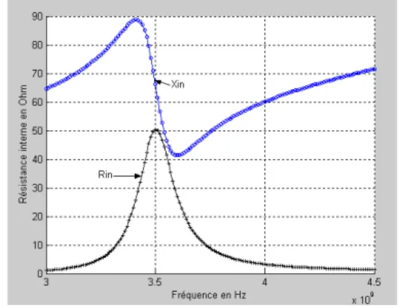
3.2 Impedance and reactance of the antenna input
patch.
It can be seen in figure 5, that the input resistance is represents the real part of the input impedance that is 49.98 Ω is (always positive), which corresponds to a resonance frequency of 3.5 GHz.
Fig 5 Input resistance of the patch antenna λ/8 as a function of the frequency.
For this frequency there is a imaginary part (reactance) of the input impedance of this antenna that due to the coaxial probe inductance, and represents the metal losses and reflection losses at contact point between the coaxial probe and the patch λ/8.
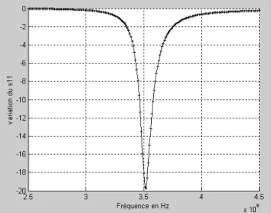
3.3 Reflection Coefficient
The following curve shows the reflection coefficient as a function of the frequency:
Fig.6: Reflection coefficient as a function of the frequency of the patch antenna λ / 8 before adaptation
Observed on the figure 6, that the reflection coefficient has a value of -19.6 dB at a resonant frequency of 3.52 GHz. It is a low value that shows the mismatch patch antenna caused by the reactance. And the value of the bandwidth of the patch antenna is very small, that is 124 MHz (3.5% of center frequency).
3.4 Standing Wave Ratio
The standing wave ratio as a function of frequency is given by the figure 7:
Fig7. Standing wave ratio as a function of frequency of a patch antenna λ / 8 before adaptation.
The SWR has a value of 1.62 at the resonant frequency of 3.55 GHz, is used to calculate the bandwidth for patch antenna but it is low, this due always to the mismatch impedance caused by the reactance.
4. Adaptation of the patch antenna
λ
/ 8 with
a capacitive reactance.
Let now a capacitor in the middle of the coaxial probe as shown in the figure 8.
Fig 8 Geometry of the patch antenna with the capacitor.
The equivalent circuit find by the TLM method of this structure is:
Fig.9 Equivalent circuit of the patch antenna λ / 8 after the addition of capacitor.
The input reactance of this antenna is the sum of the coaxial probe reactance and the reactance that has been added.
We will study the effects of Adding this capacitor on the reflection coefficient and the SWR at the resonant frequency.
4.1 Input impedance of the antenna patch
The figure 10 shows the simulation of the patch antenna
Fig 10 The input resistance and reactance of patch λ / 8 after adaptation.
The figure 10 shows that the input resistance remains the same at the resonant frequency, but the input reactance is almost zero at the resonant frequency, because of the cancellation of the probe coaxial inductive reactance caused by the capacitive reactance.
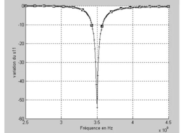
4.2 Reflection coefficient
We observe in the figure 11, an increase of the reflection coefficient with a value of -42.5 dB at the resonant frequency of 3.5 GHz.
Fig 11 Reflection coefficient as a function the frequency with the addition of capacitor.
Note, that the addition of a capacitor reactance which cancels the effect of inductive reactance causes the decrease of the reflection coefficient of the value -19.6 dB to achieve the value of -54.4 dB at the resonant frequency of 3.5 GHz, this to calculate the bandwidth of the patch antenna.
4.3. Standing Wave Ratio (SWR)
The value of the SWR is 1.1 at 3.5 GHz frequency, which shows that our antenna has been adapted (Figure 12).
Fig 12 SWR as a function of frequency after the addition of capacitor.
Since the SWR and reflection coefficient at the resonance frequency are respectively less than 2 and -10 dB, then we can calculate the value of the bandwidth of the patch antenna. The value of the bandwidth after the adaptation capacitor is 160 MHz (4.4% of center frequency).
5. Conclusion
We conclude that the simulation of the patch antenna λ / 8 at frequency of the WIMAX technology is necessary to improve the reflection coefficient and standing wave ratio. To compensate the reactance due to the inductive effect of the coaxial probe, it can be done by adding capacitor to the dielectric substrate.This increases the bandwidth from 3.5% to 4.4%.
References
[1] Abdelwaheb Ourir “Applications de matériaux à bandes interdites Photoniques et de matériaux en télécommunications“. Thèse de doctorat en sciences : Université de Paris XI d’Orsay, 2006.
[2] J.R. James, and P.S. Hall, “ Handbook of microstrip antennas “, I.E.E. Electromagnetic Waves Series 28 - Peter Peregrinus LTD, 1989.
[3]G.TROUILLARD, “contribution à l’étude des phénomènes électromagnétiques lies aux futurs systèmes mobiles de réception hertzienne a bord des véhicules automobiles. Conception, réalisation et tests des antennes correspondantes“, Thèse de doctorat en télécommunications : Université de Limoges, France, 2003.
[4] M. DIBLANC, “développement du concept de l’antenne a résonateur BIE pour la génération de la polarisation circulaire “, Thèse de doctorat, université de limoges, France 2006.
[5] N. FAURE-MURET, “ Conception, réalisation et tests des filtres millimétriques volumiques micro-usinées’’, Thèse de doctorat, Université de Limoges , France, 2005.
[6] L. FRAYTAG, “Conception, réalisation et caractérisation d’antennes pour stations de base des réseaux de télécommunications sans fil“, Thèse de doctorat, Université de Limoges. France, 2004.
[7] M.Grzeskowiak, “Antennes multicouches intégrées sur arséniure de gallium à 24 GHz pour applications antennes actives faible portée“. Thèse d’Etat, Université de Lille. France, 1999.
Adnane LATIF born in El Jadida, Morocco in
1973, Doctor of Telecommunications , and Microwaves from Cadi Ayyad University, is a researcher in the areas of smart antennas, antennas miniaturization, location in mobile networks, W LAN, WWAN. Actually professor in Cadi Ayyad University.
Founder and Coordinator of the Spring School 2010 "Wireless Communications and Emerging Technologies."
Founder and President of the Moroccan Association of Technology, Telecommunications and Electronics Member organizing partner of the Spring School 2011 "Wireless Communications and Emerging Technologies." Member Organizer of the International Conference ICMS 2005, 22-24 November 2005, Marrakech, Morocco. Member of International Program Committee of several
international conferences: -IEEE ICIT 20058-10 December 2004, Tunisia.