A Proposal to the Supervision of Processes in an Industrial Environment with
Heterogeneous Systems
Rodrigo B
S
OUZAAdelardo A D
M
EDEIROSJoão M A
N
ASCIMENTOHeitor P
G
OMESAndré L
M
AITELLIUFRN - Universidade Federal do Rio Grande do Norte
UFRN-CT-DCA / Campus Universitário / 59072-970 Natal – RN – Brazil
[email protected] [email protected] [email protected] [email protected] [email protected]
Abstract – The need to manage the production in different
in-dustrial sectors creates a strong demand for process informa-tion. Information is generated and presented by a supervisory system, by collecting and treating raw data from the processes. Data can arrive from different physical processes and through different communication protocols and/or access media. This paper proposes an acquisition methodology to allow the super-visory system to access data independently of these characteris-tics of the process and of the communication channel.
I. INTRODUCTION
Supervisory systems for industrial processes are also known as SCADA (Supervisory Control and Data Acquisi-tion) systems [1]. A SCADA system must be able to process information and make it available to the operator of the proc-ess or any other user of the supervision software [2]. It can also work in the supervisory control level to directly act on the process [3], sometimes including a certain degree of machine intelligence.
A supervisory system in an automated industrial environ-ment is essentially composed of four eleenviron-ments [4]:
1) Physical Process: it is the object of the supervision and the main element of the overall system.
2) Control Hardware: it is used in the physical interface and to control the process.
3) Supervision Software: it acquires, treats and distributes process data.
4) Communication Network: it is the responsible for the traffic of information.
An industry can have several different physical processes in its production environment. The monitoring of these proc-esses is done in a specific way for each kind of process. However, information needed by the management about all the processes should be presented in a unified way. We call this kind of environment an environment of heterogeneous processes.
The process control hardware is basically composed of sensors, actuators and controllers. A controller has the impor-tant role of maintaining the process working and stable. Be-sides, it must also provide a physical interface to access process data.
Many times, in industrial environments, several kinds of controllers are used. Each controller can have a specific way to access and store process data. This implies a variety of
communication methods. This kind of industrial environment will be called an environment of heterogeneous devices.
In this paper we call heterogeneous systems those systems inserted into industrial environments of heterogeneous proc-esses and/or heterogeneous devices. We call an automation subsystem each distinct pair formed by one physical process and its corresponding control hardware.
The supervision software (called supervisor, for short) must access the field devices to obtain process data. Data must be treated to become useful information. Another im-portant role of the supervisor is to provide data to higher-level management software. The usual situation in many heterogeneous systems is to use a distinct supervisor for each different automation subsystem.
The communication network is in charge of the informa-tion traffic and is used by the supervisory system while ac-quiring process data. Usually, it is composed of two subnet-works: the field network and the supervision local network.
Field networks permit data exchange between controllers and sensors/actuators by means of point-to-point connections carrying input/output signals [5]. To achieve a deterministic communication, the majority of field networks are based on a master-slave architecture. In this kind of network, slave con-trollers never initiate a communication. These concon-trollers only respond to requests made by the master controller. Some of the more usual implementations of the master-slave architecture in industrial environments are the modbus [6] and profibus [7] networks.
The supervision local network almost always uses LANs (Local Area Network) based on Ethernet TCP/IP [8,9]. This LAN provides the communication medium needed to share process information. The supervisors usually use supervision local networks based on the client-server architecture to share this information [10,11].
In several heterogeneous industrial systems, data acquisi-tion and informaacquisi-tion presentaacquisi-tion is a very specific procedure for each automation subsystem. In this context, many of the current supervisors can be used with one and only one sub-system. Consequently, data integration for information man-agement is a more difficult task.
II. PROPOSED SOLUTION
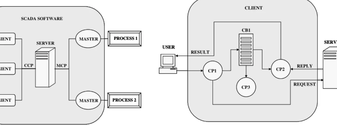
Each subsystem of a heterogeneous SCADA is composed of one or more clients, a single server and one or more mas-ters accessing the processes. This paper proposes virtually grouping the several supervision subsystems into a single system, according to the schema in Fig. 1. The supervision system must be able to use the existing supervision and field networks and must allow several simultaneous clients.
For that, this system must have a standardized communica-tion interface between the new server and the clients of all subsystems. In the same way, we have to standardize com-munication between the server and the masters of all subsys-tems. The communication standards between the clients and the server and between the server and the masters will be called CCP (Client Communication Protocol) e MCP (Master Communication Protocol), respectively (see Fig. 2).
A. Clients
Clients translate requests from the users into CCP func-tions. These functions, when possible, are independent from the physical process. The CCP function is sent to the server with the request id and the virtual address of the physical process. When the server sends back the corresponding reply, the client exhibits it to the user.
B. Server
The server receives CCP requests from the clients. The vir-tual address of the process is used to determine the corre-sponding master and the physical address of the actual proc-ess. After verifying the validity and syntax of the CCP func-tion, it is translated into one or more MCP functions. The MCP functions are then sequentially sent to the appropriate master. When the MCP requests are received, they are even-tually combined, translated and sent to the clients.
C. Masters
The masters are in charge of communication with the physical processes through the control hardware. In this case, the controllers are the slave stations in the field network. Masters receive the MCP functions from the server and trans-late them into native functions of the controllers. The an-swers of the controllers are sent to the server.
III. IMPLEMENTATION
This section presents one possible computational imple-mentation of the proposed architecture. The impleimple-mentation is divided into three applications: client, master and server.
A. Client Application
The client application sends requests to the server and treats the replies it sends back. For this, three concurrent processes have been used. The first process, Client Process 1 (CP1), waits for a solicitation from the user, generates a request, sends it to the server and inserts the request into a buffer of requests without answer, Client Buffer 1 (CB1). The second process, Client Process 2 (CP2), waits for replies from the server, withdraws the corresponding request from CB1 and exhibits the result to the user. The third process, Client Process 3 (CP3), generates timeouts by periodically inspecting the CB1 buffer to assess the elapsed time since each request was sent. Fig. 3 illustrates that architecture.
SCADA SOFTWARE SCADA
USERS PROCESS
PROCESS 1
PROCESS 2 SCADA SOFTWARE
SCADA SOFTWARE SCADA
USERS PROCESS
PROCESS 1
PROCESS 2
Fig. 1. Supervision by grouping the automation subsystems.
CLIENT
USER
CP1
CP3
CP2
SERVER CB1
REQUEST REPLY RESULT
CLIENT
USER
CP1 CP1
CP3 CP3
CP2 CP2
SERVER CB1
REQUEST REPLY RESULT
Fig. 3. The client application.
SCADA SOFTWARE USERS
CLIENT
CLIENT
CLIENT
SERVER
CCP
MASTER
MASTER MCP
PROCESS 1
PROCESS 2 SCADA SOFTWARE
SCADA SOFTWARE USERS
CLIENT CLIENT
CLIENT CLIENT
CLIENT CLIENT
SERVER
CCP
MASTER MASTER
MASTER MASTER MCP
PROCESS 1
PROCESS 2
B. Server Application
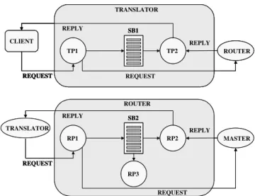
The server is divided into two sub-applications: the transla-tor and the router, as in Fig. 4. The former translates CCP functions to MCP functions. The latter routes the MCP func-tions to the appropriate master.
The translator has two concurrent processes: Translator Process 1 (TP1) and Translator Process 2 (TP2). TP1 re-ceives a request from a client, maps the CCP function into a set of MCP functions, insert them into a buffer of mapped functions, Server Buffer 1 (SB1), and sends them to the router. TP2 waits for replies from the router and, when one of them arrives, verifies if all the MCP requests corresponding to one CCP request have already been executed. If yes, it sends the CCP reply to the client and eliminates all the set from the SB1 buffer. If no, the status of the MCP request in the SB1 buffer is changed to already executed.
The router is formed by three processes: Router Process 1 (RP1), Router Process 2 (RP2) and Router Process 3 (RP3). RP1 receives the requests MCP from the translator, routes them to the appropriate masters and inserts them into the buffer of requests waiting for replies, Server Buffer 2 (SB2). RP2 waits for answers from the masters and, when they ar-rive, removes the corresponding requests from SBS and sends the reply to the translator. The RP3 process cyclically examines the SB2 buffer looking for timeouts: when one is found the request is withdrawn from the buffer and the trans-lator is notified.
C. Master Application
The master is the simplest element of the SCADA soft-ware. Its main function is responding to server’s requests by communicating with the physical process. To execute this function it uses three concurrent processes. The first process, Master Process 1 (MP1), receives MCP requisition from the server and converts them to the language understood by the
actual controller connected to the process (modbus, profibus, etc.). This requisition is then inserted into an execution queue, Master Buffer 1 (MB1). A second process, Master Process 2 (MP2), cyclically executes the first request in the MB1 queue, sends the answer to the server and removes the requisition from the queue. The third process, Master Process 3 (MP3) periodically inspects the MB1 queue to detect time-outs. The overall operation of the master is showed in Fig. 5.
IV. APPLICATION AND RESULTS
This section shows an application of the implemented ar-chitecture: a SCADA software to be used in the automation of oil wells. This application is a result of a partnership be-tween the UFRN and the Brazilian petroleum company Petrobras.
The system to be supervised is a very heterogeneous one, mainly because the region where the supervisor will be used is large and has more than 3,000 wells. The existing field network that connects the controllers of the wells to the mas-ter compumas-ter is based on low-band (9600bps) radio links. The wells use different methods of oil elevation and different controllers: each pair (elevation method x controller) can adopt a different communication protocol and used to be monitored by specific supervision softwares.
The main methods of artificial elevation currently used in oil industry [12] are:
• Gas-lift (GL) – compressed gas is injected into the well to elevate the oil to the surface.
• Electrical Submersible Pumping (ESP) – a cable transmits energy to an electric motor, coupled with a submerged centrifugal pump that generates pressure to elevate the oil.
• Sucker Rod Pumping (SRP) – The rotation move-ment of a motor is converted into an up and down movement of a rod. A pump at the end of the rod uses the up and down movement to produce a cy-clic pumping of the oil to the surface.
• Progressive Cavity Pumping (PCP) – a
progres-sive cavity pump is immersed in the oil well. The
TRANSLATOR
CLIENT
TP1 TP2
SB1
REQUEST
REPLY REPLY
ROUTER
REQUEST
ROUTER
RP1 RP2
SB2
REQUEST
REPLY REPLY
MASTER
REQUEST RP3
TRANSLATOR
TRANSLATOR
CLIENT
TP1 TP2
SB1
REQUEST
REPLY REPLY
ROUTER
REQUEST TRANSLATOR
CLIENT CLIENT
TP1
TP1 TP2TP2
SB1 SB1
REQUEST
REPLY REPLY
ROUTER
REQUEST
ROUTER
RP1
RP1 RP2RP2
SB2 SB2
REQUEST
REPLY REPLY
MASTER
REQUEST RP3
RP3 TRANSLATOR
Fig. 4. The server application.
MASTER
MP1 MP2
SERVER
MB1
REQUEST
REPLY REPLY
REQUEST
MP3 TIMEOUT
PROCESS MASTER
MP1
MP1 MP2MP2
SERVER
MB1
REQUEST
REPLY REPLY
REQUEST
MP3 MP3
TIMEOUT
PROCESS
geometry of the pump creates a set of hermetical cavities. When the pump’s rotor turns, the cavities progressively move along the pump’s axis and push the oil towards the surface.
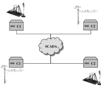
Each one of these artificial elevation methods has its own variables to be monitored, characterizing a heterogeneous processes environment. Besides, because of the particulari-ties of each process and its monitored signals, several auto-mation companies have developed specific controllers, char-acterizing an environment of heterogeneous devices. Fig. 6 illustrates a heterogeneous system with four possible automa-tion subsystems: two methods of artificial elevaautoma-tion (GL and SRP) and two distinct control equipments (C1 and C2).
Because of their particularities, the automation subsystems we can observe in Fig. 6 are normally automated by different enterprises. Fig. 7 shows a situation where users need
infor-mation from different wells in two distinct autoinfor-mation sub-systems: the users shall interact with different SCADA soft-wares. Using the architecture proposed in this paper, a single client interface can obtain information from all wells, creat-ing the situation represented in Fig. 1.
Our first supervision system using the proposed architec-ture is being used to monitor nine wells using the Gas-Lift elevation method and ZAP-500 controllers made by the HI Tecnologia Brazilian enterprise. Currently, new automation subsystems are being added to the system to allow monitor-ing thousands of Sucker Rod Pumpmonitor-ing wells with different controllers. The first prototype of the new version is moni-toring two of these wells. Fig. 8 presents the main screen of the implemented client application.
The field network uses the previously existing structure composed of master computers and radio links with trans-mission rate of 9,600 bps and a mix of proprietary and mod-bus protocols. The private communication network (intranet) of Petrobras is used as the supervision local network.
An illustrative (and simplified) step-by-step example of what happens inside the system is the following:
1) The client periodically generates GET-INFO requests.
GET-INFO is a CCP function to obtain several general parameters of a well; these parameters are presented in the main screen of the client application (Fig. 8). At a given instant, a GET-INFO9624 request is generated, where 9624 is the virtual address of one of the wells be-ing presented in the main screen.
2) The GET-INFO 9624 request is stored into the CB1 buffer and sent to the server, using the local network. 3) The server analyses the request and the database to
conclude that the 9624 well is a Gas-Lift well with a certain controller. Using this information, the GET-INFO request is decomposed into several MCP requests (GET-GASPRESSURE, GET-FLOW, etc.) by the server’s translator. These requests are stored into the
Fig. 8. Main screen of the implemented client application.
SCADA
C2 C1
C1 C2
SCADA SCADA
C2 C2 C1
C1 C1
C1 C2C2
Fig. 6. Heterogeneous system for oil artificial elevation with four possible automation subsystems.
SCADA SOFTWARE 1
SCADA SOFTWARE 2 SCADA
USERS PROCESS
SCADA SOFTWARE 1
SCADA SOFTWARE 2 SCADA USERS
SCADA SOFTWARE 1 SCADA SOFTWARE 1
SCADA SOFTWARE 2 SCADA SOFTWARE 2
SCADA
USERS PROCESS
SB1 buffer and communicated to the router.
4) The server’s router uses database information to con-clude that the well’s physical address is 39 and that the well number 39 is connected to the master number 3. Using this information, the MCP requests GET-GASPRESSURE 39, GET-FLOW 39 and so on are stored into the SB2 buffer and sent to the master. 5) The master receives the MCP requests and stores them
into the MB1 buffer.
6) The master broadcasts by radio a modbus GET-GASPRESSURE 39 request, addressed to the control-ler of the well number 39. This request was chosen be-cause it was the first one in the MB1 buffer.
7) The well controller responds to the modbus request with a GET-GASPRESSURE 44.5 reply using the link ra-dio of the field network. The number 44.5 is the cur-rent gas pressure value in the well number 39.
8) The master receives the modbus reply from the control-ler and sends a MCP GET-GASPRESSURE 44.5 re-ply to the server. The corresponding request is removed from the MB1 buffer and the next request in the buffer (GET-FLOW) is sent to the well’s controller (step 6). 9) In parallel, the server’s router receives the MCP reply.
The corresponding request is removed from the SB2 buffer and the arrival is communicated to the translator. 10) The GET-GASPRESSURE request is marked as already
executed in the SB1 buffer by the server’s translator. Then it verifies if all the MCP requests mapped from the CCP GET-INFO request were attended. This is not the case, because the GET-FLOW request and others have not yet been executed, so the server waits.
11) The steps from 6 to 10 are repeated with the other MCP requests (GET-FLOW, etc.).
12) When all the MCP requests are executed, these requests are removed from the SB1 buffer and the server’s trans-lator sends a CCP GET-INFO reply to the client. This reply contains the current gas pressure value (44.5), the current flow of oil and so on.
13) The client removes the corresponding CCP request from CB1 and shows the results to the final user. A new
GET-INFO request can be generated concerning the next well in the list.
The low band of the radio links between the well’s control-ler and the master computer can introduce severe delays in the system when multiple clients are monitoring wells con-nected to the same master.
To minimize this problem, a buffering procedure was in-troduced in the master application. All requested information is stored before being sent to the server. If another client requests the same piece of information and the buffered one is recent, the already available value is immediately sent to the server and a new use of the link radio is avoided. We also introduced a pooling procedure: when the link radio is not being used, the master autonomously requests information from the controllers, to update the buffered values.
V. CONCLUSIONS
The implementation of the prototype showed that is possi-ble to evolve from several mono-user master-slave subsys-tems to one multi-user client-server supervisor software.
One advantage of this architecture is its applicability to heterogeneous systems. Any user with access to the supervi-sion network can remotely access information about a proc-ess, no matter which automation subsystem the process is based on. Only the server (not the clients) needs to know details about communication with the slave stations. Changes in the control hardware of processes are transparent to users.
As communication between clients and the server is based on a standard protocol, different human-machine interfaces (dedicated applications, web-based interfaces, etc.) can be implemented and simultaneously used.
REFERENCES
[1] J. Melendez, J. Colomer and J. L. Rosa, “Expert super-vision based on cases,” 8º IEEE International Confer-ence on Emerging Technologies and Factory Automa-tion, 2001.
[2] L. B. Becker, W. Pardi Jr and C. E. Pereira, “Proposal of an integrated object-oriented environment for the design of supervisory software for real-time industrial automa-tion systems,” Fourth International Workshop on Ob-ject-Oriented Real-Time Dependable Systems, 1999. [3] E. Ozdemir and M. Karacor, “Run time position
estima-tion with basic sensors in real time SCADA applica-tions,” 7º International Workshop on Advanced Motion Control, 2002.
[4] A. Daneels and W. Salter, “What is SCADA?,” 7º Inter-national Conference on Accelerator and Large Experi-mental Physics Control Systems, 1999.
[5] S. Viturri and D. Miorandi, “Hybrid Ethernet/IEEE 802.11 networks for real-time industrial communica-tions,” 10º IEE International Conference on Emerging Technologies and Factory Automation, 2005.
[6] Modicon Industrial Automation Systems, Modbus Pro-tocol Reference http://www.eecs. um-ich.edu/~modbus, 2004
[7] PROFIBUS, Descrition Técnica Profibus,
http://www.profibus .org.br, 2002
[8] A. S. Tanenbaum, Redes de Computadores, Editora Campus, 1997
[9] J. Jasperneite and J. Feld, “PROFINET: An integration plataform for heterogeneous industrial communication systems,” 10º IEE International Conference on Emerg-ing Technologies and Factory Automation, 2005. [10] G. Bucci and C. Landi, “A distributed measurement
architecture for industrial applications,” IEEE Transac-tions on Instrumentation and Measurement, 2003 [11] L. Zhi and Z. Hao, “The study and realization of
SCADA system in manufacturing enterprises,”