SISAL: A SUPERVISORY SYSTEM FOR OIL WELLS
Lennedy C. Soares
∗Adelardo A. D. Medeiros
∗André L. Maitelli
∗∗Department of Computer Engineering and Automation
Universidade Federal do Rio Grande do Norte, Natal, RN, Brazil
RESUMO
SISAL: Um Sistema Supervisório para Poços de Petróleo
A elevação artificial na indústria de petróleo utiliza uma vari-edade de métodos e equipamentos de automação específicos para cada método. Os sistemas de supervisão para estes pro-cessos geralmente são dedicados a um único método e/ou a um único fabricante. Para evitar esse problema, foi desenvol-vido o sistema de supervisão SISAL, concebido para supervi-sionar poços com diferentes métodos de elevação e diferentes equipamentos de automação. O SISAL está atualmente em operação em vários estados brasileiros. Este trabalho mostra como esse sistema foi desenvolvido e apresenta alguns de-talhes dos módulos do SISAL que lidam com o método de elevação artificial denominadoPlunger Lift.
PALAVRAS-CHAVE: sistemas supervisórios, métodos de elevação artificial, plunger lift
ABSTRACT
Artificial lifting in oil industry uses a variety of methods and specific automation equipments for each method. Supervi-sory systems to these processes are usually specific for a unique method and/or for a unique manufacturer. To avoid this problem, it has been developed a supervisory system named SISAL, conceived for supervising wells with different lift methods and different automation equipments. SISAL is now in operation in several Brazilian states. This work shows
Artigo submetido em 11/03/2011 (Id.: 01301) Revisado em 31/05/2011, 21/09/2011, 09/11/2011
Aceito sob recomendação do Editor Associado Prof. Carlos Roberto Minussi
how this system has been developed and presents some de-tails of the SISAL’s modules dealing with the artificial lift method called Plunger Lift.
KEYWORDS: supervisory systems, artificial lift methods, plunger lift
1
INTRODUCTION
When automatic equipments are widely dispersed in a large number of places or in hazardous places, process data acqui-sition is difficult and sometimes impossible. The SCADA (Supervisory Control and Data Acquisition) systems have been developed for collecting, clustering and exhibiting data from dispersed equipments.
A supervisory system in an automated industrial environ-ment is essentially composed of four layers (Daneels e Salter, 1999):
1. Physical Process: what is being supervised.
2. Control Hardware: physical interfaces which acquires data and controls process.
3. Supervision Software: acquires process data from phys-ical interfaces and treats and distributes it.
4. Communication Network: the responsible for managing data traffic.
the general-purpose SCADA systems are not adequate and specific software shall be developed and used.
Stojkovic e Vukasovic (2006) upgraded a SCADA system for acquiring data generated by an Energy Management System. One constraint was that previous investments in infrastruc-ture should be preserved. The system developed by Stancel et al. (2008) is another example of a specific SCADA system for acquiring data in real time (in this case, data from an ur-ban water distribution network). In both cases, they had to manage communication between Programmable Logic Con-trollers (PLCs) and a server. The former adopted its own communication layer, while the later acquires data through an OPC server where the communication management is ac-complished by a specific hardware. Another approach was adopted by Jie et al. (2006), that developed a SCADA sys-tem for wind power plants which communicates through a CAN network.
Jian et al. (2005) focused on real time databases in SCADA systems, in the context of a system which supervises energy grids. Their main concern is how to keep system information updated.
These works deal with some of the same problems existing in oil industry, more precisely, in supervising oil lifting pro-cess. The first similarity is that on-shore oil wells are usually sparsely disposed in a large area, unlike a factory where pro-cesses are in a closed and relatively small area. Furthermore, layers of control of hardware and communication network usually have characteristics as low transmission rate and pro-prietary protocols.
Oil wells produce different kinds of oil, requiring different ways to produce it and different types of automation equip-ments. For each type of equipment there is a different way to show process information and different data to be acquired.
The ways to pump oil are called artificial lift methods and can be performed by different kinds of pumps: electric sub-mersible pumps, progressing cavity pumps and sucker rod pumps. Another way to lift oil is using gas excess, like in methods called gas lift and plunger lift (Thomas, 2001).
Each artificial lift method has different kinds of data acquired by PLCs. Another difficulty is the lack of standardization among PLCs from different manufacturers. A naive solu-tion for these problems, widely used in oil industry, would be making a different software for each manufacturer and for each artificial lift method. A better solution can be based on using a software able to deal with different equipments and different artificial lift methods.
The SISAL software (Souza, 2005) was developed to super-vise oil wells with different types of artificial lift method and
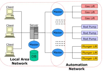
Figure 1: SISAL’s architecture
different PLC manufacturers. The SISAL software is cur-rently in operation in several states of Brazil, supervising more than 4000 wells with various methods of artificial lift.
This work shows the software architecture of SISAL and how its modules operate. After that, the general architecture is exemplified by the implementation of modules specific to the pluger lift method, the latest one included in SISAL up to now.
2
SISAL’S ARCHITECTURE
The supervisory system in oil industries is usually composed of several semi-independent subsystems. One of the con-straints while developing SISAL was that the system should be able to use the previously existing supervision and field networks and allow simultaneous clients.
The proposed system is based on a distributed architecture (see Fig. 1). Each well has a PLC and a radio that broadcasts collected data, usually at low rates1. All radios connected to the same master computer use the same frequency; therefore, only one of these PLCs can transmit simultaneously.
Master computers are disposed in specific geographic posi-tions, from where they can communicate by radio with sev-eral wells in the same region2. These regions are called pro-duction fields3. The master computers are connected to a corporate Ethernet network. Another computer, called server and also connected to the same corporate Ethernet network, centralizes data flow between clients and masters. One
spe-1
In our case, baud rates vary from 4600 up to 19200 bps 2
Radios range is about 100 km 3
cific master communicates with a database management sys-tem (DBMS).
The different modules can be developed and updated inde-pendently, provided that, we enforce a standard communi-cation interface between the server and all clients and be-tween the server and masters. These communication stan-dards are called CCP (Client Communication Protocol) and MCP (Master Communication Protocol), respectively.
For example, if SISAL is installed and PLCs from a different manufacturer have to be included into the system, it will be necessary to modify a field master for acquiring data of this kind of PLCs. This update will be hardly noticed by users be-cause of the low level of the field masters in the architecture (Fig. 1). On the other hand, supervision software systems usually used by oil industries are frequently dedicated to a unique manufacturer: if you change field equipments, you will have to change the supervisory software.
Moreover, existing supervisory systems for oil lifting are al-most all dedicated to a unique elevation method. SISAL was extended for dealing with five different artificial lift methods: rod pump, progressing cavity pumps, electric submersible pumps, gas-lift and plunger lift (Thomas, 2001). To incor-porate a new method, new PLCs and a new field master have to be installed; also, new supervision screens for that method are created. This procedure is easier than creating an entire new software and training time is reduced, because the soft-ware is almost the same.
SISAL was developed in C++ for increasing real time per-formance. Some details about the implementation of the proposed architecture can be found in previous articles from the authors (Souza et al., 2006; Medeiros et al., 2006). We present here a brief introduction about these modules of the SISAL system.
2.1
Client
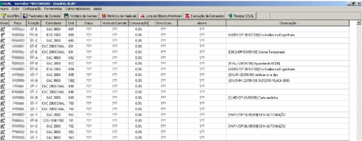
Clients translate requests from users, usually generated using a graphical interface, into CCP functions. These functions, when possible, are independent from physical process. The CCP function is sent to the server with the request ID and the virtual address of the physical process. When the server sends back the corresponding reply, the client exhibits it to the user, as can be seen in Fig. 24 5
.
SISAL also provides a communication channel based on the standard OPC protocol. This protocol allows using commer-cial visualization software systems and makes easier
integrat-4
Data in the figures 2 and 3 have been blurred to protect private informa-tion from the oil company.
5
The text is written in Portuguese because it is exhibiting the real soft-ware developed.
ing SISAL into corporate automation networks. So, users can use SISAL with a generic visualization software based on OPC or with its own client software. The former allows using a previously existing supervision screen and does not require a specific training if the operator already knows the OPC-based software. The later allows including procedures to analyze data, and not only to exhibit it. For example, it is possible to calculate and show information with high compu-tational cost, such as downhole dynamometer card for the ar-tificial lift method rod pump and production trends for wells.
2.2
Server
The server receives CCP requests from clients. The virtual address of the process is used to determine the correspond-ing master and the physical address of the actual process. After verifying the validity and syntax of the CCP function, it is translated into one or more MCP functions. The MCP functions are then sequentially sent to the appropriate mas-ter. When the MCP requests are received, they are eventually combined, translated and sent to clients.
2.3
Masters
The masters are in charge of communication with the physi-cal processes through the control hardware. In this case, the controllers are the slave stations in the field network. Mas-ters receive the MCP functions from the server and translate them into native functions of the controllers. The answers of the controllers are sent to the server.
3
SISAL AND PLUNGER LIFT
Each artificial lift method can have different supervised vari-ables as pressure, electric current, oil flow, lifted load and displacement time. Therefore, the differences among artifi-cial lift methods oblige the corresponding SISAL modules to have some specificities. We will exemplify showing the mod-ules conceived for the artificial lift method called plunger lift.
Plunger lift method works by injecting gas into a well for lift-ing fluids to surface. As gas has a lower density than liquid, it raises and the upward movement of gas carries the liquid with it. Wells based on the plunger lift method have a plunger which separates injected gas from liquid.
3.1
Client
Figure 2: Client Screen
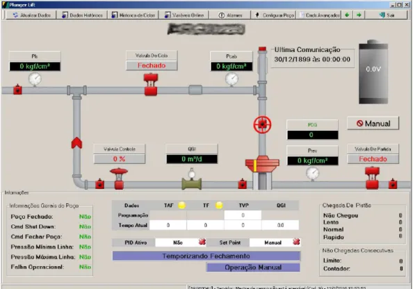
that concentrates the main information about the elevation method (Fig. 3).
Plunger lift works with injection of gas and a plunger which rises and falls periodically. Because of these characteristics, the plunger lift method has times and pressures as the main variables to be supervised. In Fig. 36
shows the main super-vised variables: Pls, Pcab, Prev, TAF, TF and TVP. The three first variables are related to pressures: pressure on production line, pressure on head of well and pressure on tubing, respec-tively. The other variables are related to the plunger: time of after flow, time of closing, time of travel, respectively.
3.2
Database Master
The Plunger lift method has a characteristic of producing an amount of data relatively bigger than other artificial lift meth-ods. Because of that, it was interesting to develop a function-ality to compress data.
The set of values to be compressed can be seen in Tab. 1. It consists of three data types: boolean, integer and real. The integer data and real data acquired from controllers are char-acterized by a small variation in values. It is possible to rep-resent data with a smaller amount of bytes, making data com-pression. Boolean can also be compressed, representing all them by a single byte.
As can be seen in Tab. 1, by removing the redundant bytes, the number of bytes is 25; otherwise, with redundancy, it is 52 bytes; so, it is possible to perform an initial compression of about 52%.
A second compression is performed using the Huffman algo-rithm (Salomon, 2002), obtaining the compression rates
pre-6
The text is written in Portuguese because it is exhibiting the real soft-ware developed.
Type Data Num. Bytes Num. Total Compr.
Boolean 4 1 4 1
Integer 4 4 16 8
Real 8 4 32 16
Total 16 9 52 25
Table 1: Characteristics of Data compression
Well Sample Not Compr. Compr. %
1 1 132462 38097 71%
1 2 140994 43404 69%
1 3 232605 61471 74%
2 1 183546 55686 70%
2 2 221562 73794 67%
2 3 67446 24329 64%
3 1 145206 41901 71%
3 2 43227 10679 75%
3 3 94311 25727 72%
Table 2: Compression Result Using Huffman Algorithm
sented in Tab. 2. The average compression rate was around 70%. If both compressions are used, overall compression ra-tio increases to 86%.
3.3
Field Master
The field master acquires data from wells and transmits in-formation to the server. This SISAL module is the most spe-cialized one, because it represents the PLCs within the archi-tecture of the system.
Figure 3: Supervision Screen
through a radio channel. The connection between the field master and the PLCs is provided by a half duplex radio chan-nel with baud rate of 9600 bps. All PLCs use the same fre-quency, so the field master can communicate with only one PLC at a time. The field master and PLCs follow the master-slave architecture: a PLC only transmits when the field mas-ter requests.
The system has a low transfer rate of data (9600 bps) between PLCs and the field master. In an environment where several users can request data at the same time, the system perfor-mance could be degraded if each request from each user gen-erates a direct request to a PLC. This approach could prevent data from being acquired at a rate fast enough to fulfill the requirements of a supervisory system.
We propose a strategy to solve this limitation which opti-mizes the available communication band. The field master is always requesting data from wells, independently of re-quests from users. These autonomous rere-quests are sent con-tinuously and cyclically, spanning all wells one after another. Received data is stored into a temporary buffer, in such a way that recent data overwrites previous data from the same well.
When a new request from an user arrives, it does not neces-sarily generate a request to a well. If the values stored in the
temporary buffer are recent enough, they are sent to the user, with no need of requesting data from the PLC.
Moreover, specifically in the case of plunger lift wells, there is another characteristic that should be taken into account: PLCs and radios are powered by a battery which is charged by solar energy. The actual radios have high energy con-sumption during transmission, therefore data should not be transmitted at night. Data produced at night must be stored in a non-volatile memory for being transmitted in presence of sunlight.
So, the field master has to deal with two different categories of data:
Current Data: Information representing the current state of wells. Current data includes instantaneous values of dy-namic variables (pressures, alarms, etc.) and informa-tion about the last cycles of the plunger (time to rise, periodicity, etc.).
When sunlight returns, the field master has to acquire both current and historical data. The question is how to share the available communication band between these two types of data:
• if we continue using all transmission time to acquire
current data, the temporary buffer will always be up-to-date, but historical data will never be recovered and will be lost.
• if we start receiving only historical data when sun rises,
the system would become non responsive until all his-torical data is transmitted.
A compromise was adopted to solve the problem. We di-vided the transmission time in 2 windows, in such a way that the window dedicated to current data is maximized. The time slot dedicated to historical data is calculated to guarantee that all available data will be transmitted before sunset. An al-gorithm was proposed to dynamically calculate the time for each type of data (Soares et al., 2010).
The equation 1 calculates the time spent for acquiring data (Soares et al., 2010). Based on that equation is possible to know how much time will be spent for acquiring all data. That information makes possible to increase or decrease the window time specified to the Historical Data. Based on that it is possible to acquire the Historical Data without loss of data.
d=
K ∑
j=1
N ∑
i=1
(Tai,j+Thi,j) (1)
The equation 1 only works if the equation 2 is satisfied.
∑K i=1Hi,1
B < D (2)
Where:
• Nis the number of PLCs
• Kis the number of acquisitions for each PLC. • Hi,tis the data stored in the PLCiat timet • dis the time of acquisition of all data in PLCs
• Tai,j is time for acquiring Current Data of PLC i on
interactionj
• Thi,j is time for acquiring Historical Data of PLCion
interactionj
• Bis the rate of communication • Dis the time of sun light in one day
4
CONCLUSION
Presently, the SISAL software is supervising more than 4000 wells in Brazil, based on five artificial lift methods: plunger lift, electric submersible pumps, progressing cavity pumps, sucker rod pumps and gas-lift. For each one of these meth-ods, SISAL can deal with PLCs and radios from different manufacturers. The proposed architecture is flexible enough to incorporate new artificial lift methods.
Some specificities about the communication system and about the plunger lift method were described. The charac-teristics of this method influenced the development of some algorithms for optimizing communication and compressing data.
Some lines of development under analysis or being imple-mented are:
• Cryptography and security increasing.
• Development of web-based clients, in addition to
the clients currently in use (OPC-based and SISAL-specific).
• Increasing the capacity of exporting data in different
formats and protocols.
THANKS
We would like to thank Petrobras for funding the AUTOPOC project, which made this work possible.
REFERENCES
Daneels, A. e Salter, W. (1999). What is SCADA?, Inter-national Conference on Accelerator and Large Experi-mental Physics Control Systems.
Jian, W., Yong, C. e Schulz, N. (2005). Overview of real-time database management system design for power system SCADA system, Proceedings of the IEEE Southeast-Con., pp. 62 – 66.
Jie, W., Jinming, Y., Songguang, Z., Qing, X. e Xiaochao, W. (2006). Design of supervisory system based on CAN bus for wind power plant,IEEE International Sympo-sium on Industrial Electronics., Vol. 3, pp. 1679 – 1682.
Medeiros, A. A. D., Nascimento, J. M. A., Maitelli, A. L., Gomes, H. P. e de Souza, R. B. (2006). SISAL - um sistema supervisrio para elevao artificial de petrleo,Rio Oil & Gas Expo and Conference, Vol. 1, pp. 1–6.
Soares, L. C., Protsio, A. D. D. e Medeiros, A. A. D. (2010). Superviso de poos de petrleo com o mtodo de elevao ar-tificial plunger lift,XVIII Congresso Brasileiro de Au-tomtica.
Souza, R. B. (2005). Uma arquitetura para sistemas super-visrios industriais e sua aplicao em processos de elevao artificial de petrleo, Master’s thesis, Universidade Fed-eral do Rio Grande do Norte.
Souza, R. B., Medeiros, A. A., Nascimento, J. M., Gomes, H. P. e Maitelli, A. L. (2006). A proposal to the super-vision of processes in an industrial environment with heterogeneous systems.,Proceedings of IECON - Inter-national Conference of the IEEE Industrial Electronics Society, Paris, France.
Stancel, E., Stoian, I., Kovacs, I., Gyurka, B. e Balogh, S. (2008). Urban water supply distributed control system,
IEEE International Conference on Automation, Quality and Testing, Robotics., Vol. 3, pp. 316 – 320.
Stojkovic, B. e Vukasovic, M. (2006). A new SCADA system design in the power system of Montenegro -ICCP/TASE.2 and web-based real-time electricity de-mand metering extensions,Power Systems Conference and Exposition, 2006. PSCE ’06. 2006 IEEE PES, Vol. 1, pp. 2194 – 2199.