Journal of Engineering Science and Technology Review 7 (4) (2014) 66-72
Dynamic Vibration Analysis of Heavy Vehicle Truck Transmission Gearbox Housing
Using FEA
Ashwani Kumar* and Pravin P Patil
Department of Mechanical Engineering,Graphic Era University Dehradun, India 248002
Received 1 August 2013; Accepted 29 September 2014
___________________________________________________________________________________________
Abstract
The main objective of this original research article is to study the loose fixture mounting affect of heavy vehicle transmission gearbox housing. The studies were completed in three phases. In first phase the aim was to find the actual suitable boundary condition. After finding the boundary condition in second phase the fixture bolts were loosened to monitor the affect of looseness and in third phase the positional looseness based study were completed. The looseness of transmission housing causes heavy vibration and noise. In order to prevent this noise and vibration the transmission housing is tightly mounted on the chassis frame using bolts. In our design transmission housing is constraint on chassis frame using 37 bolts. Truck transmission system determines the level of noise together with the chassis, engine and bodywork. Vehicle transmissions under torsional vibration condition caused rattling and clattering noises. Reciprocity Principle was used to determine the failure frequencies for transmission housing. In reciprocity principle gear and shafts are suppressed and all the forces transmitted through the bearings are applied on the empty housing. FEA based ANSYS 14.5 has been used as analysis tool. The free vibration frequency for zero displacement condition varies from 1669 Hz to 2865 Hz and for loose transmission casing frequency varies from 1311 Hz to 3110 Hz. The analysis have theoretical and practical aspects and useful for transmission housing structure optimization.
Keywords:Transmission Housing, Constraint Bolts, Housing Looseness, Zero Displacement, Natural Frequency.
__________________________________________________________________________________________
1. Introduction
Automobile noise and vibration reduction is a continous progressive field and researchers have done various studies. A brief literature review has been conducted. Jiri Tuma [1] has studied the noise and vibration of transmission system. The author solved the gear noise problem by introducing an encloser to reduce radiated noise. TARA trucks were selected as a research object. The Fourier Transform is used for the analytical analysis. The natural frequency of vibration is varying in between 500 Hz to 3500 Hz at varying rpm. The severe vibration occurs at the frequency range of (500-2500) Hz. In this study the casing of TARA trucks was not considered so in other study casing can be considered. Mats Åkerblom [2] has performed a literature review and concluded that transmission error is an important excitation mechanism for gear noise and vibration. In addition to transmission error, friction and bending moment are another reason responsible for failure. He has also analyzed the dynamic behaviour of a gearbox. Leila et al. [3] have studied the heavy gearbox of helicopters. To prevent break down and accident in helicopters gear fault detection is important. Spectrum analysis and Cepstrum analysis method is used to identify damage gear. Timothy J et al. [4] have studied the source of vibration. A Sports Utility
Vehicle with sensor and data acquisition system is used to find the vibration source. This study was focused on vehicle vibration response from road surface features. Chinmaya et al. [5] have used motor current signature analysis (MCSA) and discrete wavelet transform (DWT) for studying the gear vibration. Transmission errors and internal excitation causes vibration and noise problem. P. Czech [6] has described the vibroacoustic diagnostics of high-power toothed gears. The presented analysis is a experimental work done in a steel plant. R. Singh [7] has done two case studies for the vibro-acoustic analysis of automotive structures. Analytical and experimental results are presented for brief description. In first case passive and adaptive hydraulic engine mounts and in second case welded joints and adhesives in vehicle bodies were considered. Ashwani Kumar et al. [8] have studied the vibration problem of transmission casing using four different materials. The frequency varies from (1002-3784) Hz. The article have investigated the variation of natural frequency with material mechanical properties and authors have concluded that material properties influenced the frequency. Gabriele Vandi et al. [9] have presented the implementation of a simplified engine-driveline model to complete an existing vehicle dynamic model. The engine model is based on maps which are expressed as function of engine speed and load request. Lei Yulong et al. [10] have focused his study on a dual-clutch automatic transmission of its hydraulic system. We can calculate the structure size of each body through theory and practical algorithm. The
J
estr
JOURNAL OF Engineering Science andTechnology Review
www.jestr.org
______________
* E-mail address: [email protected]
dynamic simulation model of hydraulic system of dual clutch automatic transmission was established. S¨ureyya Nejat Dogan [11] have investigated the cause of rattling and clattering noise and concluded that torsional vibration is the main reason of vibration. Shawki S et al. [12] have used vibration response analysis method for the analytical analysis of car gearbox system. He has performed analytical and experimental analysis of a car transmission system. By using physical properties, he has calculated the radiation efficiency, and the vibration response was measured.
Ashwani Kumar et al. [13] have studied the truck transmission housing using grey cast iron FG260 as housing material. The authors have find out the natural frequency and mode shapes of housing, natural frequency varies from (1002-2954) Hz. Fujin Yu et al. [14] have studied the automobile transmission gearbox. They have used structural optimization method to reduce the noise and vibration of gearbox. Mohamed Slim Abbes et al. [15] have performed the numerical simulation of the overall dynamic behaviour of a parallel helical gear transmission. A dynamic sub-structuring method was used to determine the natural frequencies and the corresponding mode shapes.
Transmission housing vibration is a special vibration condition caused by looseness of mounting bolts, which is used to connect housing to the chassis frame. In this research article, we have study the transmission loosening problem. The study was completed in three phases-First phase of the study is concern with the condition when all the 37 bolts are constraint at its position, and in second phase one, two and three bolts were loosen from all position to check the dynamic response of the loosened transmission housing. In third stage positional looseness based problem were studied. The vibration signatures for first ten modes were studied for all three conditions.
2. Establishment of CAD Model of Transmission Housing
The designing of transmission housing were done using Solid Edge and Pro-E [17-18] software. The geometrical dimensions were obtained from maintenance workshops and drawing in Dehradun with the permission of manufacturer of trucks. To get the accurate results we have constructed full complex model of loading trucks transmission gearbox housing. The CAD model is shown as figure 1. For vibration analysis, FEA based software ANSYS 14.5 [16] has been used. Finite Element Analysis (FEA) is based on meshing of big domain in small domain known as elements. These elements are connected at nodes. ANSYS 14.5 have high quality meshing facility. Figure 3. shows FEA based meshed model of housing which consists of 1, 96,137 nodes and 1, 13,566 elements.
Fig. 1. Cad model of transmission gearbox housing.
Fig. 2. Right positional part of transmission housing.
Figure 2 shows the right positional part of transmission housing. For analysis the transmission housing were divided in five positional parts (back, bottom, front, left and right). Each positional part is connected to chassis frame and others mounting using fixture bolts. Right part is connected to automobile assemblies using 7 bolts. All positional parts have total 37 bolts to connect with chassis and other parts. The 10 mode shapes and natural frequency (Table 1) of transmission housing have been evaluated using ANSYS 14.5 solver. Different vibration modes bending, torsional effect, axial bending vibrations have been identified.
Fig. 3. FEA meshed model of transmission housing.
3. Material Properties and Selection of Boundary Conditions
Grey Cast Iron HT200 was used as a transmission housing material. It has excellent damping property to reduce vibration. The nonlinear mechanical properties of grey cast iron HT200 were also considered to study the dynamic vibration properties of housing. The grey cast iron HT200 material properties are elastic modulus – 1.10e11 Pa, poisson ratio- 0.28, density-7200 kg/m3 [14]. The mechanical properties of material are same for all three conditions.
FEA based workbench module have two boundary condition options. Free-free and fixed-fixed constraint based boundary condition but these boundary conditions are not suitable for transmission housing analysis. To overcome the drawbacks of free-free and fixed-fixed boundary conditions, zero displacement constraint based boundary condition was used for the vibration analysis. In zero displacement constraint boundary condition all 37-bolts were constraint to move. In actual use transmission housing is tightly mounted on chassis frame, so to simulate the same environment all 37 bolts were constraint and natural frequencies were evaluated.
all bolts should be fixed tightly as we have fixed all 37 bolts to the chassis frame. If bolts were, loosened it may cause heavy vibration and damage to the truck transmission housing. Figure 2 shows the right positional part of housing with 7 bolts hole. To apply the zero displacement constraint boundary condition all 7 bolt holes were fixed, in same manner all 37 bolt holes were fixed for five different positional parts. Zero displacement constraint boundary condition reduces the chances of resonance by omitting the lower range frequencies.
4. Modal Analysis Result and Discussion
Zero displacement constraint based boundary condition fixed all 37-bolt holes and provides rigid mounting and fixing of housing on chassis frame. Now the question arises that if any bolts loosened, what will be the affect on transmission operation and failure. The paper deals with the problems of loosen bolts condition. In first phase of study the zero displacement constraint based boundary condition was applied and corresponding mode shapes and natural frequency were calculated.
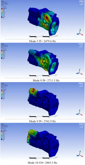
Figure 4 shows the selected mode shapes and natural frequency of transmission housing in zero displacement constraint condition. The natural frequencies varies from (1669.5-2865.5) Hz. Mode 1 & 2 is torsional vibration. This torsional vibration is performed at front and backside on transmission housing. Axial bending vibration has been find in mode 8. The 9 and 10 mode is torsional vibration. Torsional and axial bending vibration are harmful and cause large displacement and noise. Mode 9 shows the large displacement at front part. The results shows that variation of natural frequency is in upper range (1669-2865) Hz which reduces the chance of resonance condition.
Mode 1 f1= 1669.5 Hz
Mode 4 f4= 2282.8 Hz
Mode 5 f5= 2479.6 Hz
Mode 8 f8= 2711.3 Hz
Mode 9 f9= 2762.9 Hz
Mode 10 f10= 2865.5 Hz
Fig. 4. Grey cast iron HT 200 Zero displacement constraint based
condition
centre line. Figure 5 shows the different mode shapes and corresponding natural frequency for one bolts loosen condition.
Mode 1 f1= 1637.2 Hz
Mode 4 f4= 2064.9 Hz
Mode 6 f6= 2327.5 Hz
Mode 8 f8= 2551.8 Hz
Mode 9 f9= 2588.3 Hz
Mode 10 f10= 2674.5 Hz
Fig. 5. One bolt loose condition based analysis
When two fixturing bolts have been loosened the natural frequency varies in range (1340-2338) Hz (Table 1). This range of frequency is a lower order frequency. For the first
mode shape there is a difference of 329 Hz (24%) and for the tenth mode the difference is widen up and increases to 527 Hz (22%) in comparison to zero displacement constraint boundary condition. It shows that the two bolt unconstraint or loosen condition reduce the natural frequency by (22-24) % and these lower frequencies are the main reason for the excitation which causes resonance. Various modes of vibration has been identified. Mode 3,4 & 5 is torsional vibration. This torsional vibration is performed at back right side on transmission housing. Axial bending vibration has been find in 7 mode. The mode 10 is axial and torsional vibration causes heavy vibration and excess deformation at centre line. Figure 6 shows the different mode shapes and corresponding natural frequency for two bolts loosen condition.
Mode 1 f1= 1340.8 Hz
Mode 3 f3= 1649.3 Hz
Mode 5 f5= 1762.4 Hz
Mode 9 f9= 2202.2 Hz
Mode 10 f10= 2338.6 Hz
Fig. 6. Two bolt loose condition based analysis
When three bolts were loosened the natural frequency varies in range (1311-2058) Hz as shown in Table 1. For the first mode shape, there is a difference of 358 Hz (21%) and for the tenth mode the difference is widen up and increases to 807 Hz (28%) in comparison to zero displacement constraint condition when all 37 bolts were constraint . It shows that the three bolt loosen condition reduce the natural frequency by (21-28) %. Mode 1 is torsional vibration. This torsional vibration is performed at extreme backside on transmission housing. Axial bending vibration has been find in mode 5.The mode 8 & 10 is axial and torsional vibration causes heavy vibration and excess deformation at centre and front part. Figure 7 shows the different mode shapes and corresponding natural frequency for three bolts loosen condition.
Mode 1 f1= 1311.7 Hz
Mode 2 f2= 1384.2 Hz
Mode 5 f5= 1584.3 Hz
Mode 6 f6= 1686.6 Hz
Mode 8 f8= 1872.1 Hz
Mode 10 f10= 2058.9 Hz
Fig. 7. Three bolts loosen condition based analysis.
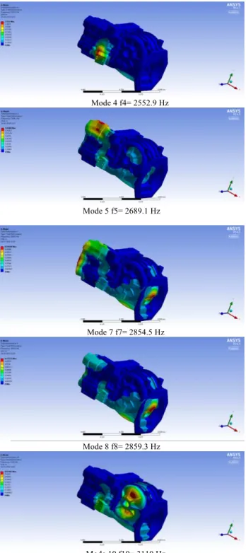
The third phase of study deals with positional looseness condition. Till now we have studied bolts base looseness condition when one, two or three bolts were loosened from all five positional parts. In positional looseness analysis all bolts were loosened only from selected positional part. Right positional part (figure 2) have 7 constraint bolts hole and for study of looseness all bolts were loosened. When all 7 bolts of right part of transmission housing were loosen from chassis frame the natural frequencies varies from (1929-3110) Hz. Figure 8 shows the selected mode shapes of loose transmission housing. For positional based condition the natural frequency was in higher order range.
Mode 4 f4= 2552.9 Hz
Mode 5 f5= 2689.1 Hz
Mode 7 f7= 2854.5 Hz
Mode 8 f8= 2859.3 Hz
Mode 10 f10= 3110 Hz
Fig. 8. Right positional part loosen condition based analysis.
Table 1. Natural frequency variation for different conditions. S.N. Zero Displacement Constraint Condition One Bolt Loosen Condition Two Bolts Loose Condition Three Bolts Loosen Condition Right positional Part Loosen Condition
1 1669.5 1637.2 1340.8 1311.7 1929.1
2 2011.2 1888.9 1534.8 1384.2 2227.8
3 2227.7 1949 1649.3 1473.4 2296.7
4 2282.8 2064.9 1697.9 1524.1 2552.9
5 2479.6 2246.9 1762.4 1584.3 2689.1
6 2599.9 2327.5 2049.3 1686.6 2692.2
7 2674.3 2456.7 2125.5 1767.6 2854.5
8 2711.3 2551.8 2141.8 1872.1 2859.3
9 2762.9 2588.3 2202.2 1988.3 3087.3
10 2865.5 2674.5 2338.6 2058.9 3110
Table 1 shows the natural frequency and mode shapes for all conditions. Figure 9 shows the graphical representation of frequency variation. For all loosened condition there is a fall in natural frequency. Torsional and axial mode of vibration causes noise and large deformation of transmission casing. The results of the study have practical and theoretical importance for transmission casing structure optimization.
a. Frequency variation of zero displacement condition (1) and one bolt loosen condition (2).
b. Frequency variation of one (1), two (2) and three (3) bolts loosen condition.
c. Frequency variation of zero displacement (1), two bolt (2) and three bolt (3) loosen condition.
Fig. 9. Frequency variation of different conditions (a, b and c).
5. Conclusion
The inherent natural frequency for zero displacement condition varies from 1669 Hz to 2865 Hz. when one fixturing bolts have been loosened the natural frequency varies in range (1637-2674) Hz and reduction in natural frequency is (2-6)% of zero displacement condition. For two bolts loosened condition the reduction in natural frequency is (22-24)% of zero displacement condition. For three bolts loosened condition the fall in frequency is (21-28)%. The study shows that looseness of transmission casing causes lower order frequency these lower order frequencies are the main reason for the excitation which causes resonance. In resonance, the transmission housings were subjected to
0 500 1000 1500 2000 2500 3000 3500
1 2 3 4 5 6 7 8 9 10
N atu ral F re q u en cy (H z) Mode Series1 Series2 0 500 1000 1500 2000 2500 3000
1 2 3 4 5 6 7 8 9 10
N atu ral F re q u en cy (H z) Mode Series1 Series2 Series3 0 500 1000 1500 2000 2500 3000 3500
1 2 3 4 5 6 7 8 9 10
heavy vibration leads to failure of transmission. Analysis condition shows that transmission housing is subjected to torsional vibration, axial bending vibration and axial bending with torsional vibration.
In conclusion, the numerical simulation of heavy vehicle transmission casing confirmed that:
1. Looseness of bolts causes heavy vibration and deformation of casing.
2. One , Two and Three bolts based study shows that there is a sharp decrement in natural frequency for bolt looseness. It vary in range from (2-28)%.
3. For one bolt loosened condition frequency decreases (2-6)%, Two bolts loosened condition (22-24)% and for three bolts (21-28)% (figure 9).
4. Right positional part loosened condition has less affect on natural frequency. The natural frequency varies from (1929-3110) Hz.
Using the realistic approach the mechanical properties of Grey cast iron HT 200 transmission housing were also considered for the analysis. The FEA simulation based analysis provides satisfactory results.
Acknowledgement
This research work has been carried out at advanced modelling and simulation lab, department of mechanical engineering which is developed from grant of Department of Science and Technology (DST), New Delhi and, Graphic Era University (GEU), Dehradun.
______________________________ References
[1] Jiri Tuma: Gearbox Noise and Vibration Prediction and Control. International Journal of Acoustics and Vibration Vol. 14 (2009) 1-11.
[2] Mats Åkerblom : Gear noise and vibration - a literature survey. Report-Volvo Construction Equipment Components AB. Research Journal of Applied Sciences, Engineering and Technology Vol. 5 (2013) 1449-1453.
[3] Leila.Nacib, KomiMidzodzi.Pekpe and Saadi Sakhara :Detecting gear tooth cracks using cepstral analysis in gearbox of helicopters.International Journal of Advances in Engineering & Technology Vol. 5 (2013) 139-145.
[4] Timothy J. Gordon and ZeviBareket : Vibration Transmission from Road Surface Features – Vehicle Measurement and Detection. Technical Report for Nissan Technical Center North America, Inc. 2007; UMTRI-2007-4.
[5] ChinmayaKar and A.R. Mohanty: Monitoring gear vibrations through motor current signature analysis and wavelet transform. Mechanical Systems and Signal Processing Vol. 20 (2006) 158– 187.
[6] P. Czech: Diagnosis of industrial gearboxes Condition by vibration and time frequency, Scale-frequency, frequency-frequency analysis. Metalurgija Vol. 51(2012) 521-524.
[7] R. Singh: Dynamic design of automotive systems-Engine mounts and structural joints. Dynamic design of automotive systems Vol. 25 (2000) 319- 330.
[8] Ashwani Kumar, Arpit Dwivedi, Himanshu Jaiswal, Pravin P Patil: Material Based Vibration Characteristic Analysis of Heavy Vehicle Transmission Gearbox Casing Using Finite Element Analysis (FEA). Advances in Intelligent Systems and Computing vol. 308 (2014) 527-533.
[9] Gabriele Vandi, NicolòCavina, Enrico Corti, Giorgio Mancini, Davide Moro, FabrizioPonti, Vittorio Ravaglioli: Development of a
software in the loop environment for automotive power train systems. 68th Conference of the Italian Thermal Machines Engineering Association, ATI2013. Energy Procedia 45( 2014 ) 789 – 798.
[10] Lei Yulong, Li Xingzhong, Liang Weipeng, Hanyong:Hydraulic System Optimization and Dynamic Characteristic Simulation of Double Clutch Transmission.3rd International Conference on Environmental Science and Information Application Technology (ESIAT 2011). Procedia Environmental Sciences 10 (2011)1065 – 1070.
[11] S¨ureyya Nejat Dogan: Loose part vibration in vehicle transmissions - Gear rattle. Tr. J. of Engineering and Environmental Science 23 (1999) , 439-454.
[12] Shawki S. Abouel-Seoud, Eid S. Mohamed, Ahmed A. Abdel-Hamid and Ahmed S. Abdallah : Analytical Technique for Predicting Passenger Car Gearbox Structure Noise Using Vibration Response Analysis. British Journal of Applied Science & Technology vol 3(2013) 860-883.
[13] Ashwani Kumar, Himanshu Jaiswal, Avichal Pandey, Pravin P Patil : Free Vibration Analysis of Truck Transmission Housing based on FEA. Procedia Materials Science vol 6 (2014) 1588-1592 [14] Fujin Yu, Yongxiang Li, DaowenSun,Wenquan Shen and
Weiqiang Xia. Analysis for the Dynamic Characteristic of the Automobile Transmission Gearbox. Research Journal of Applied Sciences, Engineering and Technology vol 5(2013) 1449-1453. [15] Mohamed Slim Abbes , Tahar Fakhfakh , Mohamed Haddar,
ArefMaalej. Effect of transmission error on the dynamic behaviour of gearbox housing. Int J Adv Manuf Technol Vol 34 (2007) 211– 218.
[16] ANSYS R 14.5.Academic, Structural analysis Guide (2013). [17] SOLIDEDGE .Version 19.0 (2006).