Journal of Computer Science 3 (12): 934-938, 2007 ISSN 1549-3636
© 2007 Science Publications
Corresponding Author: P. Nirmal Kumar, College of Engineering, Guindy Anna University, Chennai, 600025, Tamilnadu, India
Testing Virtual Reconfigurable Circuit Designed For A Fault Tolerant System
P. Nirmal Kumar, S. Anandhi, M. Elancheralathan and J. Raja Paul Perinbam
College of Engineering, Guindy Anna University, Chennai, 600025
Tamilnadu, India
Abstract: This research describes about the testing of virtual reconfigurable circuit (VRC) designed and implemented for a fault tolerant system which averages the (three) sensor inputs. The circuits that are to be tested are those which are successfully evolved in this system under different situations such as (i) all the three sensors are faultless (ii) one of the input sensor fails as open (iii) sensors fails as short circuit. The objective of this research is to test the desired optimal circuits evolved by decoding the configuration bit streams. The logic simulation tool used to perform fault simulation is AUSIM (Auburn University Simulator).
Key words: FPGA, Virtual Reconfigurable Circuit (VRC), fault tolerant system, sensor failure, AUSIM, ASL
INTRODUCTION
Ensuring the reliability of Electronic Circuits has always been a challenge. As the complexity of systems increases the inclusion of reliability measures becomes progressively more complex and often a necessity for VLSI circuits where a single error could potentially render an entire system useless.
The Evolvable Fault Tolerant system [1] is designed (1) to provide fault tolerant design automatically and (2) to ensure autonomous functional recovery for these devices after an occurrence of unavoidable damage caused by extreme radiation, temperature or simple malfunctions (e.g. severe electric transients, etc).
The way this research investigates faults differs from the conventional way of Fault Tolerance mentioned above. In this research, we will be interested in faults that can occur within the VRC, instead of focusing on environmental problems such as temperature, extreme radiation, etc. The role of fault tolerance is to deal with errors, caused by faults, before they lead to failure. This research describes about the logic simulation tool used to perform the fault simulation. AUSIM: Auburn University SIMulator was very useful in testing the architecture of Virtual Reconfigurable Circuit. It aids in debugging a circuit or in analyzing a circuit in terms of area and performance metrics. The Hardware Description Language (HDL) for AUSIM is Auburn SimulationLanguage (ASL).
VIRTUAL CONFIGURABLE CIRCUIT
The fault Tolerant System is evolved using the idea of VRC on FPGA[2] .when the VRC is uploaded in to the FPGA then its configuration bit stream determines Processing Elements (PEs) function and the places where its inputs are connected. The main advantage is that the array of PEs, the routing circuits and the configuration memory can be designed exactly according to the requirements of a given application.
VRCs require more recourses than the other common approaches used to implement a given function in an FPGA, it is realistic to suppose that their use will yield less reliable solutions. Implementation of a circuit costs a few equivalent gates in an FPGA. However, several hundred gates have to be activated if a VRC is utilized. The Pessimistic scenario says that the reliability will be decreased one hundred times in the case of use of the VRC. Hence decided to perform experiments using AUSIM simulator before physical devices will be utilized[3].
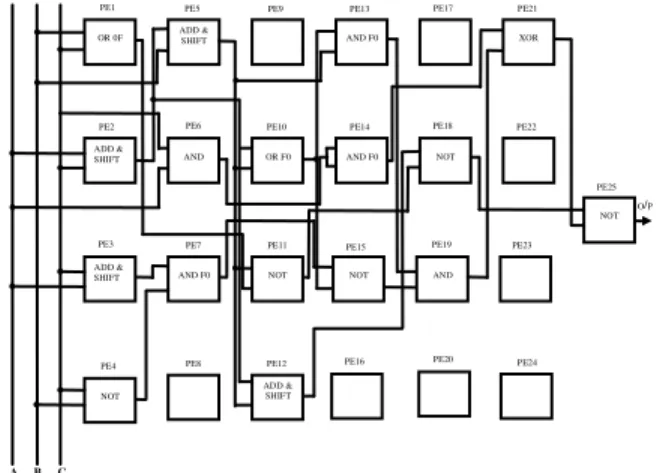
The VRC designed for this Evolvable Fault Tolerant system consists of 25 Processing Elements (PEs) and are arranged in 4 rows and 6 columns with one output PE. The general structure of VRC is shown in Fig. 1.
Fig. 1: Structure of VRC
Fig. 2: Internal structure of a processing element
Table 1: Functions of a PE
Configuring bits Functions
F0 : 000 X&Y
F1 : 001 X^Y
F2 : 010 ~X
F3 : 011 (X+Y)>>1
F4 : 100 X&”0F”
F5 : 101 X&”FO”
F6 : 110 X | “0F”
F7 : 111 X | “F0”
It is a primary concern for a designer who tests a system for its ability to tolerate against faults induced into its hardware resources, to accurately specify the possible nature of faults that may occur and how they can be effectively modeled into the system under test.
In order for the system to meet all the constraints required by fault tolerant applications[4], it is imperative for all selected Processing Elements (PEs) in the VRC to converge. Therefore, it is obvious that the most destructive scenario for the functionality of the system is to cope with the stuck-at faults that can occur in PEs (Table 1).
PE21
PE23 NOT PE25 AND
PE6
PE8
PE22 XOR
O/P
PE20 PE24 AND PE19 ADD &
SHIFT PE5
AND F0 PE7
PE9 PE13
PE16 PE17
NOT PE15 AND F0
NOT PE18 AND F0 PE14 OR F0 PE10
ADD & SHIFT PE12
A B C
PE1
ADD & SHIFT PE2
ADD & SHIFT PE3
NOT PE4 OR 0F
NOT PE11
Fig. 3: Circuit that averages three sensor inputs
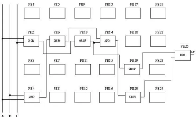
Fig. 4: Optimal circuit evolved when one of he input sensors fail as an open circuit
CIRCUITS EVOLVED IN VRC
Input from the environment enters VRC via the input interface. The architecture configuration bits determine VRCs architecture. The VRC outputs a value according to the input and its architecture bit streams. A circuit evolved that averages the (three) sensor input when all the three sensors are faultless is shown in Fig. 3.
When one of the input sensors fails as open circuit, then the optimal circuit evolved will find out the average of the remaining two inputs. The circuit evolved in this case is shown in Fig. 4. When two sensors fail as short circuit, then the optimal circuit evolved will provide the remaining one input as output, as shown in Fig. 5.
FAULT SIMULATION TOOL - AUSIM
Fig. 5: Optimal circuit evolved when two input sensors fails as short circuit
fault simulation capabilities. The fault models supported by this simulator are gate-level stuck-at faults (generates both collapsed and un collapsed fault list) and bridging faults. The type of bridging fault list generated can be the dominant, dominant-AND, dominant-OR bridging fault model. Both serial and parallel fault simulation are supported for both gate-level stuck-at and bridging faults[5] .
ASL: Auburn Simulation language is the hardware Description Language for AUSIM. The Auburn Simulation Language (ASL) description is a positional notation HDL for digital logic[6]. The ASL description represents a textual description of the circuit and requires explicit reference to a given gate or net. It consists of a single “circuit statement” and one or more component statements”. The circuit statement includes the name of the complete logic circuit, its primary inputs, and its primary outputs. Once the logic diagram has been completely specified with unique gate and net names, the circuit and component statements can be generated directly from the information in the logic diagram. The ASL file is named as:
file_name.asl
Control file: The control file basically gives an ordered list of commands. The syntax of control file is:
ausimcont_file_name
Where the cont_file_name is the name of the control file containing the commands to AUSIM for directing the desired simulation. To begin the files must be specified. If proper naming convention is used then the user can simply enter one line:
defaultfile_name
This assumes that the required input files are named as file_name.asl, file _name.vec, file_name.lib. If no library file is being used then an empty file or a file with syntactically correct commentline in it will do.
Fault simulation commands: The fltgen and bftgen
commands generate gate-level stuck-at and bridging fault lists, respectively, and writes the list to the .flt file. Normally the fltgen command produces a collapsed fault list but the uncol command preceding the fltgen
command will result in the generation of an uncollapsed fault list.
The notrip command is used to continue fault simulation of the following its initial detection. In this case the .det file information includes all vectors and primary outputs of the circuit for which the fault was detected[7]. The notrip command works only with serial fault simulation. Both serial and parallel fault simulation are supported for both gate-level stuck-at and bridging faults. The serial and parallel gate-level stuck-at fault simulation commands are fltsim and
pftsim, respectively. The serial and parallel bridging fault simulation commands are bftsim and pbfsim, respectively. Note that only one type of fault simulation command should be included in a control file.
The fltpro command produces .pro output files which gives a profile of the fault detection associated with a given set of test vectors for the circuit begin simulated in terms of the number of faults detected by a given vector along the cumulative number of faults detected at that point in the set of test vectors.
FAULT SIMULATION RESULTS
Circuit that averages three sensor inputs: The fault simulation results for the optimal circuit evolved when all the three sensors are faultless are given below.
Audit file: AUSIM (2.6) Audit Results Circuit ‘VRC’ Number of Primary Inputs = 24
Number of Primary Outputs = 8 Number of gates = 148
Number of gate I/O pins = 449 Number of nets = 172
Number of fan-out stems = 37
Number of uncollapsed gate-level stuck-at faults = 898 Number of collapsed gate-level stuck-at faults = 375 Gate type and number of uses:
NOT: 16 AND: 66 OR: 21 XOR: 45
# AUSIM (2.6) Simulation Results;
#AAAAAAAABBBBBBBBCCCCCCCCOOOOOOO; # 765432107654321076543210 76543210;
#A0toA7B0toB7C0TOC7;
10000100100001111000010110000100 10000100100010011000101110000111 10000100100010001000101010000111 10000111100001011000101110001000 10000111100010101000101110001001 100001011000101110001000 10000111
Fault simulation results:
Logic simulation time 40 ns
No. of faults generated and simulated 465
No. of faults detected 360
Fault coverage 77.42%
Parallel fault simulation time 400 ns Serial fault simulation time 2403 ns
Circuit evolved when one sensor fails as open circuit: The fault simulation results for the optimal circuit evolved when one of the sensors fails as open circuit are given below.
Audit file: AUSIM(2.6) Audit results circuit VRCOPEN
No. of primary Inputs = 40
No. of Primary Outputs = 8
No. of gates = 176
No. of gate I/O pins = 542
No. of nets = 216
No. of fan-out stems = 62
No. of uncollapsed gate-level stuck-at faults = 1084 No. of collapsed gate-level stuck-at faults = 506 Gate type and number of uses:
AND: 76 OR: 46 XOR: 54
Simulation output file: A part of the output file is given below
# AUSIM (2.6) Simulation Results,
#AAAAAAAABBBBBBBBCCCCCCCCDDDDDDD DEEEEEEEE OOOOOOOO ;
#7654321076543210765432107654321076543210 76543210~# INPUT VECTOR FILE ;
# A0 to A7 B0 to B7 C0 TO C7 D0 TO D7 E0 TO E7, 1001001110001001100100011111000000001111 10001000
1000100110001010100100011111000000001111 10001011
1000011110001001100010001111000000001111
10001000
1000101010010011100001101111000000001111 10001000
1000100010010001100111101111000000001111 10000111
1000101110000111100010101111000000001111 10001001
1001111110001010100001101111000000001111 10001100
Fault simulation results:
Logic simulation time 40 ns
No. of faults generated and simulated 614
No. of faults detected 481
Fault coverage 78.33%
Parallel fault simulation time 491 ns Serial fault Simulation time 10015 ns
Circuit evolved when two sensors fails as short circuit: The fault simulation results for the optimal circuit evolved when two sensors fails as short circuit are given below
Audit file: AUSIM (2.6) Audit Results Circuit 'VRCSHORT'
No. of Primary Inputs = 40
No. of Primary Outputs = 8
No. of gates = 64
No. of gate I/O pins = 192
No. of nets = 104
No. of fan-out stems = 8
No. of uncollapsed gate-level stuck-at faults = 384 No. of collapsed gate-level stuck-at faults =160 Gate type and number of Uses:
AND: 16 OR: 32 XOR: 16
Simulation output file: A part of the output file is given below
# AUSIM (2.6) Simulation Results;
#AAAAAAAABBBBBBBBCCCCCCCCDDDDDDD DEEEEEEEE OOOOOOOO ;
#7654321076543210765432107654321076543210 76543210
# A0 to A7 B0 to B7 C0 TO C7 D0 TO D7 E0 TO E7; 1001001110001001100100011111000000001111 11111110
1000100110001010100100011111000000001111 11100111
1000101010010011100001101111000000001111 11111101
1000100010010001100111101111000000001111 11101111
1000101110000111100010101111000000001111 11111100
Fault simulation results:
Logic simulation time 30 ns
No. of faults generated and simulated 192
No. of faults detected 127
Fault coverage 66.14%
Parallel fault simulation time 100 ns Serial fault simulation time 1092 ns
CONCLUSION
In this study, decoding the configuration bit streams using ‘C’ language evolves the desired circuit. Then the evolved optimal circuit was tested using AUSIM fault simulator. In future, the dynamic power consumption of the system will be estimated.
REFERENCES
1. Hereford, J. and C. Pruitt, 2004. Robust sensor systems using evolvable hardware. Proceedings of 2004 NASA/DoD Conference on Evolvable Hardware, Seattle, WA.
2. Lukas Sekanina, 2006. On dependability of FPGA based evolvable hardware systems that utilize virtual reconfigurable circuits. In: Conference on Computing Frontiers, pp: 221-228.
3. Stroud, C., 2006. Using the Workstation Version of AUSIM-Version 2.3, Department of Electrical and Computer Engineering, Auburn University. 4. Sekanina, L., 2003. Virtual reconfigurable circuits
for real-world applications of evolvable hardware. In: Proceeding of the 5th International Conference on Evolvable Systems: From Biology to Hardware ICES’03, Volume 2606 of Lecture Notes in Computer Science, pp: 186-197, Trondheim, Springer-Verilog.
5. Canham, R.O. and A. Tyrrell, 2002. Evolved fault tolerance in evolvable hardware, IEEE Congress on Evolutionary computation 2002, Honolulu, HI. 6. Stroud, C., 2003. ASL: Auburn University
Simulation Language, Department of Electrical and Computer Engineering, Auburn University. 7. Hereford, J. and N. Galyen, 2004. Failure detection
for multiple input system, Proceedings of 2004 IEEE SoutheastCon ,Greensboro, NC.
8. Hollingworth, Gss., Smith, S. and Tyrell, A., 2000. Safe intrinsic evolution of virtex devices. In: Proceedings of 2nd NASA/DoD workshop on Evolvable Hardware, IEEE.