Abstract—As modern processors and semiconductor circuits move into 32 nm technologies and below, designers face the major problem of process variations. This problem makes designing VLSI circuits harder and harder, affects the circuit performance and introduces faults that can cause critical failures. Therefore, fault-tolerant design is required to obtain the necessary level of reliability and availability especially for safety-critical systems. Since XOR-XNOR circuits are basic building blocks in various digital and mixed systems, especially in arithmetic circuits, these gates should be designed such that they indicate any malfunction during normal operation. In fact, this property of verifying the results delivered by a circuit during its normal operation is called Concurrent Error Detection (CED). In this paper, we propose a CED based fault-tolerant XOR-XNOR circuit implementation. The proposed design is performed using the 32 nm process technology.
Index Terms—Fault-tolerant systems, Concurrent Error Detection (CED), XOR-XNOR circuit, stuck-at fault model, transistor stuck-on fault model, transistor stuck-open fault model
I. INTRODUCTION
OS transistor scaling has been the key of the rapid advances of integrated circuits performance and density [1]. As technology advances to deep sub-micron levels and below, VLSI circuits increase in complexity and become more susceptible to process variations [2]. The primary effect of process variations is on transistor parameters. Thus, parameter variations in key device parameters such as channel length, threshold voltage and oxide thickness, are increasing at an alarming rate [3].
Manuscript received December 09, 2011; revised January 2012. K. Mouna and K. Chiraz are with the Electronic & Microelectronics Laboratory, Monastir Tunis University, Tunisia. Email: {mouna.karmani, chirazkhedhiri}@yahoo.fr
H. Belgacem is with the Electronic & Microelectronics Laboratory, Monastir Tunis University and ISSAT, Sousse, Tunisia. Email: [email protected]
K.L. Man is with the Xi'an Jiaotong-Liverpool University, China, Myongji University, South Korea and Baltic Institute of Advanced Technology, Lithuania. Email: [email protected]
E.G. Lim is with the Xi'an Jiaotong-Liverpool University, China. Email: [email protected]
C.-U. Lei is with the University of Hong Kong, Hong Kong. Email: [email protected]
The research work presented in this paper is partially sponsored by SOLARI (HK) CO (www.solari-hk.com) and KATRI (www.katri.co.jp and www.katri.com.hk).
Due to these parameter variations in VLSI circuits, transient and permanent faults arise; and they can corrupt the circuit operation. Thus, fault-tolerant designs are required to ensure safe operation of digital systems performing safety-critical functions in safety-critical devices [4]. To achieve the fault-tolerance property, it is important to increase the level of error detection. Thus, Concurrent Error Detection (CED) is important in highly dependable computing systems, because CED techniques can be used to detect permanent and transient faults in these circuits during normal operation [5]. Thereby, in applications where dependability is important, CED circuitry must be used for assuring early detection of errors preserving the state of the system and preventing data corruption [6].
The exclusive-OR (XOR) and exclusive-NOR (XNOR) are fundamental components in full adders, and in larger circuits such as parity checkers. Thus, the performance of these logic circuits is affected by the individual performance of each XOR-XNOR included in them [7-8]. In this paper, we propose a CED based fault-tolerant XOR-XNOR circuit implementation using the 32 nm process technology.
This XOR-XNOR circuit implementation is proposed to achieve the required level of reliability and robustness for schemes using the dual duplication code like adders, ALUs, multipliers and dividers. Simulation results of the implemented chip are presented and show that the technique is effective and can be easily implemented in the System-on- Chip (SoC) environment. We first present out proposed circuit topology (Section II-A) and its simulation result (Section II-B). Then we verify the proposed circuit using three typical fault models (Section III).
II.CONCURRENTERRORDETECTIONBASED FAULT-TOLERANTSYSTEMS
Process variation is caused by the inability to precisely control the fabrication process at small-feature technologies [9]. Therefore, deep-submicron technologies with lower voltage level systems are more susceptible to permanent and transient faults. Consequently, fault tolerance must be used to tolerate design faults in safety-critical systems. Thus, building fault-tolerant systems is so important for
safety-A Concurrent Error Detection Based
Fault-Tolerant 32 nm XOR-XNOR Circuit
Implementation
Mouna Karmani
,
Chiraz Khedhiri, Belgacem Hamdi, Ka Lok Man, Eng Gee Lim and Chi-Un Lei
M
Proceedings of the International MultiConference of Engineers and Computer Scientists 2012 Vol II, IMECS 2012, March 14 - 16, 2012, Hong Kong
ISBN: 978-988-19251-9-0
ISSN: 2078-0958 (Print); ISSN: 2078-0966 (Online)
critical applications (such as transport and medical applications) to ensure the correctness of the results computed in the presence of permanent and transient failures [4-6].
For safety-critical applications, the correspondent safety level requires the detection of any single fault that arises during normal operation. In order to ensure this on-line fault detection property, we can employ CED techniques. The most basic method of performing CED is hardware redundancy, i.e., two copies of the hardware are used concurrently to perform the same computation on the same data. At the end of each computation, the results are compared and any discrepancy is reported as an error [10]. In fact, the CED technique presented in this paper is achieved by means of output duplication technique. The output of a circuit has a certain property that can be monitored by a checker. If an error causes a violation of the property, the checker gives an error indication signal [5].
Exclusive-OR (XOR) and exclusive-NOR (XNOR) circuits are basic building blocks in various digital systems, especially in arithmetic circuits. Also, the performance of these logic circuits is affected by the individual performance of each XOR-XNOR circuit included in them. Thus, each XOR-XNOR gate included in these circuits must be fault-tolerant to be able to continue operating even with failures in their hardware [11]. XOR and XNOR circuits implement functions that are complementary. XOR and XNOR circuits are binary operations that perform the following Boolean functions [11]:
A XOR B = A ⊕ B=A~B + AB~
A XNOR B=A Θ B= AB + A~B~
where (A, A~) and (B, B~) are complementary pairs of data. The XOR and XNOR circuits can be implemented in different architectures by using different circuit designs. Examples of design techniques for XOR-XNOR circuits are static CMOS logic, pass transistor logic, CMOS pass transistor logic, double pass transistor logic and transmission gate [11-12].
Pass transistor logic uses fewer transistors to implement important logic functions. Also, smaller transistors and smaller capacitances are required, and it is faster than conventional CMOS. However, the pass transistor gates generate degraded signals, which slow down signal propagation [13].
A. The proposed XOR-XNOR circuit implementation
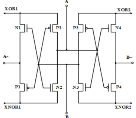
In this paper, a novel XOR-XNOR circuit designed in modified pass transistor logic is presented in Fig. 1. The current implementation does not generate degraded signals. This gate has dual inputs (A, A~, B and B~) and generates duplicated dual outputs (XOR1, XNOR1) and (XOR2, XNOR2). The circuit implementation is performed with eight MOS transistors.
In the current XOR-XNOR circuit, the fault-tolerance property is ensured by using a duplicated output computation based concurrent error detection method. In
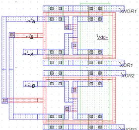
fact, this CED method is based on generating duplicated dual outputs. The first path gives the first outputs (XOR1 and XNOR1); and the second path gives the second outputs (XOR2 and XNOR2). Errors caused by faults will affect only one of the two paths and may be detected just by checking the complementarity principle between each (XOR, XNOR) function. The proposed XOR-XNOR circuit and the correspondent layout are respectively given by Fig. 1 and Fig. 2.
Fig. 1. The proposed XOR-XNOR circuit implementation with duplicated output computation
The XOR and XNOR functions are both performed using two different paths. From the first path we obtain XOR1 and XNOR1 functions (1). In this path the inputs are A, A~, B and B~, but the input B~ is performed from the input B. Thus, the circuit will be insensitive to any kind of errors affecting the input B~.
XOR1= A XOR B=A~B + A(B~)
XNOR1=A XNOR B= AB + A~(B~)
From the second path, we obtain XOR2 and XNOR2 functions (2). In this path, the inputs are A, A~, B and B~, but the input A~ is performed from the input A. Thus, the circuit will be insensitive to any kind of errors affecting the input A~.
XOR2= A XOR B=(A~)B + AB~ XNOR2=A XNOR B= AB + (A~)B~
Thus, this XOR-XNOR circuit implementation can increase the fault tolerance property, since the circuit outputs are computed using the output computation of two paths.
B. Simulation results
The XOR-XNOR circuit is implemented in full-custom 32 nm technology [14]. SPICE simulations of the circuit extracted from the layout, including parasitic, are used to demonstrate that the circuit has a conformed electrical behaviour.
(1)
(2)
Proceedings of the International MultiConference of Engineers and Computer Scientists 2012 Vol II, IMECS 2012, March 14 - 16, 2012, Hong Kong
ISBN: 978-988-19251-9-0
ISSN: 2078-0958 (Print); ISSN: 2078-0966 (Online)
Fig. 2. Layout of the XOR-XNOR circuit in full-custom 32 nm process technology
SPICE simulation of the circuit without any fault is illustrated by Fig. 3.
Fig. 3. SPICE simulation of the XOR-XNOR circuit in 32nm technology without faults
From this simulation we can remark that the outputs (XOR1, XNOR1) and (XOR2, XNOR2) obtained by this computation technique are complementary, therefore the circuit is fault-free. Also, as indicated in the previous section, the current implementation does not generate degraded output signals and can produce strong 1’s and 0’s. This is important, especially with low voltage levels and small noise margins.
III.THE XOR-XNOR CIRCUIT FAULT ANALYSIS Due to the diversity of VLSI defects, it is hard to generate complementary tests for real defects. Therefore, fault models are necessary to analyse any VLSI circuit in the presence of faults. In the following sub-sections, we analyse the behaviour of our XOR-XNOR circuit with respect to the set of fault models including logical stuck-at faults, transistor stuck-on and transistor stuck-open faults.
A. The stuck-at fault model
The most common model used for logical faults is the single stuck-at fault. It assumes that a fault in a logic gate results in one of its inputs or the output is fixed at either a logic 0 (stuck-at-0) or at logic 1 (stuck-at-1) [15]. So, for inputs, we consider the logical stuck-atfault model. Table I gives the response of the gate for all inputs combinations.
TABLEI
THE GATE RESPONSE FOR ALL INPUTS COMBINATIONS
A A~ B B~ xor1 xnor1 xor2 xnor2 Conclusion
0 0 0 0 0 0 0 0 Multiple fault (detected) 0 0 0 1 0 0 0 1 (detected & corrected) Single fault 0 0 1 0 0 0 1 0 (detected & corrected) Single fault 0 0 1 1 0 0 1 1 Multiple fault (detected) 0 1 0 0 0 1 0 0 (detected & corrected) Single fault 0 1 0 1 0 1 0 1 Valid input 0 1 1 0 1 0 1 0 Valid input 0 1 1 1 1 0 1 1 (detected & corrected) Single fault 1 0 0 0 1 0 0 0 (detected & corrected) Single fault 1 0 0 1 1 0 1 0 Valid input 1 0 1 0 0 1 0 1 Valid input 1 0 1 1 0 1 1 1 (detected&corrected) Single fault 1 1 0 0 1 1 0 0 Multiple fault (detected) 1 1 0 1 1 1 1 0 (detected&corrected) Single fault 1 1 1 0 1 1 0 1 (detected&corrected) Single fault 1 1 1 1 1 1 1 1 Multiple fault (detected)
From the table above, we can conclude that for primary logical stuck-at faults, all single and multiple faults on primary inputs will result in a non-valid code by producing no complementary outputs. In other words, each fault will be detected when there are non complementary (XOR, XNOR) outputs, because normally XOR and XNOR should be complementary data. We should note that the error detection is achieved by using only one of the two paths. Also, the fault-free outputs are available on the second path. (The concurrent error correction is available only for single stuck-at faults).
However, not all defects in VLSI circuits can be represented by the stuck-at fault model. It has been shown that transistor stuck-on and transistor stuck-open are two other types of defects that may remain undetected if testing is performed only based on the stuck-at fault model [13-15]. Next, we consider the stuck-on and stuck-open transistor fault model. We will examine all possible single transistor stuck-on and transistor stuck-open faults within the circuit of Fig. 1in next two sub-sections.
B. The transistor stuck-on fault model
A stuck-ontransistor fault involves the permanent closing of the path between the source and the drain of the transistor (PMOS or NMOS). In other words, a transistor stuck-on
Proceedings of the International MultiConference of Engineers and Computer Scientists 2012 Vol II, IMECS 2012, March 14 - 16, 2012, Hong Kong
ISBN: 978-988-19251-9-0
ISSN: 2078-0958 (Print); ISSN: 2078-0966 (Online)
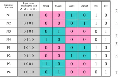
fault may be modelled as a bridging fault from the source to the drain of a transistor [15]. In order to analyse the circuit behaviour in the presence of stuck-on faults with realistic circuit defects, we simulate the considered XOR-XNOR circuit in the presence of faults. Faults are manually injected in the circuit layout of Fig. 2. Table II states the circuit response for all possible single transistor stuck-on faults. Two signals EI1 (Error indication 1) and EI2 (Error indication 2) are obtained by checking the principle of complementarity respectively between (XOR1, XNOR1) and (XOR2, XNOR2). EI1 and EI2 are generated using respectively the first path and the second path outputs computation.
TABLEII
THE GATE RESPONSE FOR TRANSISTOR STUCK-ON FAULTS
Transistor Stuck-on
Input vector detecting the fault
A A~ B B~ XOR1 XNOR1 XOR2 XNOR2 EI1 EI2
N1 1 0 0 1 0 0 1 0 1 0
N2 0 1 0 1 0 0 0 1 1 0
N3 0 1 0 1 0 1 0 0 0 1
N4 0 1 1 0 1 0 0 0 0 1
P1 1 0 1 0 0 0 0 1 1 0
P2 0 1 1 0 0 0 1 0 1 0
P3 1 0 0 1 1 0 0 0 1 0
P4 1 0 1 0 0 1 0 0 0 1
If a fault appears, it only affects one of the two paths. Consequently, a fault producing no complementary outputs affects only one of the two error indication signals (EI1 and EI2). Each error detection signal can be generated using a pass transistor XOR gate.
C. The transistor stuck-on fault model
A stuck-opentransistor involves the permanent opening of the connection between the source and the drain of a transistor [15]. When a transistor is rendered non-conducting by a fault, it is said to be stuck-open. In our fault model, a single physical line in the circuit is broken. In fact, by examining the layout of the circuit given by Fig. 1, we can remark that transistors N1, N2, P1 and P2 have the same gate which is connected to the input B. Also, transistors N3, N4, P3 and P4 have the same gate which is connected to the input A. The transistors gates for each output block are connected in such a way that a single break in any transistor gate does not make the transistor stuck-open. Therefore, we need two breaks to make any transistor stuck-open. Thus, this property makes the circuit fault-tolerant for single stuck-open fault model.
In this section, we have shown that the scheme of the Fig. 1 is fault-tolerant for the logic stuck-at fault model, transistor stuck-on and stuck-open fault model.
IV.CONCLUSION
With the continuous scaling of devices and interconnects, the geometrical feature size decreases from submicron to the sub-nano and beyond. Therefore, process variations become
relatively more important and VLSI complex circuits are more susceptible to permanent and transient faults. Therefore, designing fault-tolerant systems providing continuous and safe operation in the presence of faults become important, especially in specific applications domains requiring very high levels of reliability. In this paper, we have presented a Concurrent Error Detection based fault-tolerant XOR-XNOR circuit implementation, and have verified the proposed circuit using different fault models. The proposed circuit can significantly improve the reliability and robustness for schemes using the dual duplication code such as adders, ALUs, multipliers and dividers.
REFERENCES
[1] M. White and Yuan Chen, “Scaled CMOS Technology Reliability Users Guide”, NASA Electronic Parts and Packaging (NEPP) Program, 2008.
[2] M. Orshansky, S. R. “Nassif and D. Boning, Design for manufacturability and statistical design: A constructive approach”, US Springer, 2008, pp. 1–8.
[3] R. Garg and S. P. Khatri “Analysis and Design of Resilient VLSI Circuits: Mitigating Soft Errors and Process Variations”, US Springer, 2010, pp. 1-10.
[4] E. F. Hitt and D. Mulcar, “Fault-Tolerant Avionic”, CRC Press LL, 2001.
[5] C. Zeng and E. J. McCluskey, “Finite State Machine Synthesis with Concurrent Error Detection”, Proc. International Test Conference, 1999, pp. 672-679.
[6] D. Das and N. A. Touba, “Synthesis of Circuits with Low-Cost Concurrent Error Detection Based on Bose-Lin Codes”, Journal of Electronic Testing: Theory and Applications, Vol. 15, Nos. 1/2, Aug. 1999, pp. 145-155.
[7] M. Nicolaidis, R. O. Duarte, S. Manich, and J. Figueras, “Fault-Secure Parity Prediction Arithmetic Operators”, in IEEE Design & Test of computers, Vol. 14, Apr 1997, pp. 60-71.
[8] S .R. Chowdhury, A. Banerjee, A. Roy and H. Saha, “A High Speed Transistor Full Adder Design using Novel 3 Transistor XOR Gates”, In International Journal of Electronics, Circuits and Systems II, 2008, pp. 217-223.
[9] S. R. Sarangi, B. Greskamp, R. Teodorescu, J. Nakano, A. Tiwari, and J. Torrellas, “VARIUS: A model of process variation and resulting timing errors for microarchitects,” in IEEE Transactions on Semiconductor Manufacturing, vol. 21, February 2008. pp. 3-13. [10] N. Joshi, K. Wu, J. Sundararajan, and R. Karri, “Concurrent Error
Detection for Evolutional Functions with applications in Fault Tolerant Cryptographic Hardware Design”, IEEE Transactions on Computer-Aided Design of Integrated Circuits and Systems, vol. 25, 2006, pp. 1163–1169.
[11] H. Mishra, S. Wairya, R. K. Nagaria, and S. Tiwari, “New Design Methodologies for High Speed Low Power XOR-XNOR Circuits”, World Academy of Science, Engineering and Technology, vol. 55
2009, pp. 200-206.
[12] S. Mishra, A. Kumar and R.K. Nagari, “A comparative performance analysis of various CMOS design techniques for XOR and XNOR circuits”, International Journal on Emerging Technologies, vol. 1, 2010, pp. 1-10.
[13] B. Hamdi, C. Khedhiri, and R. Tourki, “Pass Transistor Based Self-Checking Full Adder”, International Journal of Computer Theory and Engineering, Vol. 3, No. 5, 2011, pp. 608-616.
[14] E. Sicard, “Microwind and Dsch version 3.1,” INSA Toulouse, ISBN 2-87649-050-1, Dec 2006.
[15] P.K. Lala, “An introduction to logic circuit testing”, Morgan & Claypool, 2009, pp. 1–9.
Proceedings of the International MultiConference of Engineers and Computer Scientists 2012 Vol II, IMECS 2012, March 14 - 16, 2012, Hong Kong
ISBN: 978-988-19251-9-0
ISSN: 2078-0958 (Print); ISSN: 2078-0966 (Online)